Page is loading ...

DOUBLE TRACK LOW HEADROOM (LHR) CONVERSION KIT
I N STA LL AT I O N
INSTRUCTIONS
DOUBLE TRACK LOW HEADROOM (LHR) CONVERSION KIT
FOR USE WITH STEEL DOORS ONLY
CLOPAY CONSUMER SERVICES • 1-800-225-6729
MATERIALS NEEDED (NOT INCLUDED) TOOLS NEEDED (NOT INCLUDED)
This Double Track Low Headroom (LHR) Conversion Kit is designed to
modify the minimum headroom clearance required.
■ Reduces headroom requirements to 4-1/2" for extension springs and
EZ-SET® extension spring system
■ Reduces headroom requirement to 9-1/2" for EZ-SET® torsion
spring system
CAUTION
Carefully read the following instructions before beginning
installation of the Double Track Low Headroom Conversion
Kit. Installation of this kit should be done by a person with
reasonable mechanical aptitude.
PARTS INCLUDED
PARTS, MATERIALS AND TOOLS
(2) LHR EZ-SET®
Extension Spring System
Housing Brackets
(14) Track Bolts
1/4" × 5/8"
(4) Hex Head Bolts
3/8" × 1"
(14) Flange Nuts
1/4" Diameter
(4) Hex Nuts
3/8" Diameter
(2) LHR Top
Brackets
Measuring Tape
Square
Hacksaw
Marker
Drill
Drive Bit
1/4" Drill Bit
Angle Punch Iron 9/16" Socket
9/16" Wrench
Adjustable Wrench
Gloves
Safety Glasses
Ladder
Rope
LHR Front Upper Track (1 pair)
Starter Angle and (1) Junction Plate
LHR Rear Upper Track (1 pair)
and (2) Junction Plates
(2) LHR Safety
Bottom Brackets

2
DETERMINE TRACK RADIUS
1
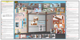
Step 1 - Determine Track Radius
■ This kit is designed to modify the minimum headroom clearance required
(see chart below). This kit works with both 12" and 15" radius horizontal
track. To determine track radius, measure from the center point of the
radius to the bottom of the track as shown by dimension “R” (Fig. 1).
EZ-SET® Extension
Spring System Extension EZ-SET® Torsion
Spring System
Minimum
Headroom 4-1/2" 4-1/2" 9-1/2"
■ If dimension “R” measures 11" to 12", then the track radius is 12". If “R”
measures 14" to 15", then the track radius is 15".
■ Also measure and check the headroom distance, which is the space
above the top of the opening (Fig. 2).
Fig. 1
“R”
Right
Side
Left
Side
Door Width
Finished Floor Level
Inside of Garage
Looking Out
Ceiling
Fig. 2
Headroom
Door Height

3
PREPARE VERTICAL TRACK AND FLAG BRACKET
2
Step 2-A Determine Reduced Vertical Track Length
■ Refer to Table 1 to determine reduced vertical track length.
Table 1
Reduced Vertical Track Length
Door Height 12" Radius 15" Radius
6'6" 65" 61-1/2"
7'0" 71" 67-1/2"
7'6" 77" 73-1/2"
8'0" 83" 79-1/2"
NOTE: For door heights with 4-1/2" of headroom not listed in Table 1,
take height of door in inches and subtract 12" for 12" radius or
15-1/2" for 15" radius to get reduced vertical track length.
NOTE: Actual opening (vehicle) clearance is opening height minus 6"
(e.g.: 7' high doors installed with double track low headroom hardware
will have an opening clearance of 6'6").
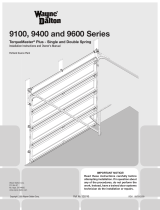
Step 2-B Cut Vertical Track
■ Measure correct length to be removed and mark using marker and
square (Fig. 3A).
■ Using a hacksaw, remove excess length from top of vertical track,
ensuring a square cut (Fig. 3B).
Step 2-C Drill Vertical Track
NOTE: Drilled holes MUST be in correct position to ensure proper
alignment.
■ Two 1/4" diameter holes need to be re-drilled at the top of the vertical
track. Measure correct position or use the cutoff track from the opposite
side – ip over, align and use as a template. These two holes are used to
attach the vertical track to the ag bracket (Fig. 3C).
Step 2-D Check Flag Bracket Clearance
■ Hold ag bracket in position on reduced vertical track to check clearance.
Step 2-E Cut Flag Bracket
NOTE: DO NOT cut ag bracket if your door is using the
EZ-Set Torsion Spring System.
■ If there is a clearance problem, cut 3" off the top of the ag bracket.
■ Measure and mark with marker (Fig. 3E).
■ Cut off top of ag bracket using a hacksaw (Fig. 3F).
Step 2-F Re-attach Flag Bracket
■ Re-attach ag bracket to top of vertical track using track bolts in the
bottom row of holes.
Fig. 3
Cut Off 3"
(If Necessary)
3/4"
7/16"
3A
3B
3C
3E
3F
1/4"
Drill
Mark
Mark
Cut
Cut
5/8"
Vertical
Track
Cut Off
(See Table 1)
Flag
Bracket
Right Side Shown, Left Side is a Mirror Image

4
ATTACH SAFETY BOTTOM BRACKETS
3
For Extension and EZ-SET® Extension Spring Systems Only
Step 3-A Attach Safety Bottom Brackets
WARNING
Heavy-duty bottom brackets (not provided) are required
for doors over 250 lbs. Using standard bottom brackets for
doors over 250 lbs. can result in severe injury when spring
tension is applied. Call the toll free number provided with the
main instruction manual if your door weighs over 250 lbs.
■ Safety bottom brackets are positioned with ears located on bottom. “L”
and “R” letters stamped on brackets designate left-hand and right-hand
brackets (inside looking out) (Fig. 4).
■ Mount right-hand LHR safety bottom bracket to right side of bottom
door section by inserting the safety bottom bracket locking tabs into end
stile key slots. Push inward, then up, to fully engage bottom bracket in
end stile.
■ Fasten the safety bottom bracket to the door using (2) #14 × 5/8" sheet
metal screws provided in the standard door hardware (Fig. 5).
■ Repeat procedure for opposite side.
WARNING
Failure to properly engage locking tabs on bottom bracket
into key slots on edge of door can result in severe injury when
spring tension is applied.
Step 3-B EZ-SET® Extension Spring System and
Extension Springs Only
Hook looped ends of lift cable over buttons on safety bottom brackets
(Fig. 6).
NOTE: DO NOT attach looped ends of lifting cables to bottom brackets
at this time if using the EZ-SET ® torsion spring system.
For EZ-SET® Torsion Spring System Only
Step 3-C Attach Safety Bottom Brackets
The safety bottom brackets that came with the door, NOT the safety bottom
brackets in this kit, are to be used for this setup. Follow standard installation
for safety bottom brackets. (See instruction manual).
WARNING
Heavy-duty bottom brackets (not provided) are required
for doors over 250 lbs. Using standard bottom brackets for
doors over 250 lbs. can result in severe injury when spring
tension is applied. Call the toll free number provided with the
main instruction manual if your door weighs over 250 lbs.
WARNING
Failure to properly engage locking tabs on bottom bracket
into key slots on edge of door can result in severe injury when
spring tension is applied.
Fig. 4
EarsEars
“L” Designates Left-Hand Bracket “R” Designates Right-Hand Bracket
Fig. 5
Locking
Tabs
Low Headroom Safety Bottom Bracket
(Right-Hand Side Shown)
Fig. 6
Loop End of CableSteel Door Section
Low Headroom
Safety
Bottom Bracket
“R” Designates
Right-Hand Bracket
Button
End Stile
Key Slots

5
Fig. 7
REFERENCE MAIN INSTALLATION INSTRUCTIONS
4
Step 4 - Reference Main Installation Instructions
Using the instruction manual supplied with the door, complete Steps 4
through 12 of the “Installing the New Door” section. Once completed,
proceed to Step 5.
Step 5 - Align, Mark/Drill and Attach LHR Front Upper Track
■ Remove existing horizontal track mounting bracket from horizontal track by
drilling rivets or removing track bolt.
■ Align LHR front upper track with standard track using indicated holes (Fig. 7A).
Mark position of lower splice plate hole (Fig. 7B).
■ Drill a 1/4" hole at marked position on standard track.
■ Mount the LHR front upper track to standard track with (3) 1/4" × 5/8" track
bolts and ange nuts. Follow track bolt placement (Fig. 7C).
■ Repeat the above attachment for the opposite track.
ATTACH LHR FRONT UPPER TRACK
5
Mark/Drill
Align
7A
7B
7C

6
Fig. 8
Step 6 - Align, Mark/Drill and Attach LHR Rear Upper Track
■ Align LHR rear upper track with standard track so that the gap between the
LHR front track and LHR rear upper track is not greater than 1/8" (Fig. 8A).
Mark position of lower front splice plate hole (Fig. 8B).
■ If existing holes do not align, drill a 1/4" hole at marked position on
standard track.
■ Mount the LHR rear upper track to standard track with (2) 1/4" × 5/8"
track bolts and ange nuts. Follow track bolt placement (Fig. 8C).
■ Repeat the above attachment for the opposite track.
NOTE: To correctly position the LHR rear upper track, the back of the
LHR rear upper track has a vertical slot on it. Align to this slot.
ATTACH LHR REAR UPPER TRACK
6
Mark/Drill
Align
8A
8B
8C

7
JOIN HORIZONTAL TRACK ASSEMBLY AND VERTICAL TRACK
7
Step 7 - Join Horizontal Track Assembly
and Vertical Track
■ Temporarily support the rear end of the horizontal track assembly with a
rope from the trusses overhead, or a tall ladder (Fig. 9A).
■ Attach curved end of lower horizontal track to the ag bracket with
(2) 1/4" × 5/8" track bolts and 1/4" ange nuts so that the heads of the
screws are on the inside of the track. Track installation with 2" thick
doors use outside (2) slots (Fig. 9B). Track installation with 1-3/8" thick
doors use inside (2) slots (Fig 9C).
■ Attach the starter angle to the ag bracket by aligning them with a
3/8"-16 × 3/4" carriage bolt and 3/8" ange nut included with the
door. track installation with 2" thick doors use outside slot (Fig. 9D). track
installation with 1-3/8" thick doors use inside slot (Fig 9E).
■ The horizontal track and vertical track must join together to form a
continuous channel for the rollers.
■ Repeat the above attachment for the opposite track assembly.
NOTE: Flag bracket height may vary depending on headroom. If 3"
was cutoff in Step 2-E, the removed portion is indicated in gray.
Fig. 9
2" Overhead View
Overhead View
2" Thick Doors
Use Outside (2) Slots
1-3/8" Overhead View
Overhead View
1-3/8" Thick Doors
Use Inside (2) Slots
9A
9D
9B
9E
9C

8
ATTACH LOW HEADROOM TOP BRACKET TO TOP DOOR SECTION
9
Step 8 - Attach Low Headroom Top Bracket
to Top Door Section
■ Insert stand-alone roller into low headroom top bracket (Fig. 11A).
■ Insert roller/low headroom top bracket assembly into top horizontal track
(Fig. 11B).
■ Slide low headroom bracket toward top section until low headroom
bracket is tight against the end stile (Fig. 11C). If a top strut has been
installed on the section, the top roller bracket will go between the strut
and the section, with the roller above the strut (Fig. 11D).
■ Line up low headroom top bracket with the side of the top section. Using
both slots in each low headroom bracket as a guide, drill 5/32" pilot
holes in the center of each slot.
■ Attach top bracket to end stile using (2) #14 × 5/8" sheet metal
screws for steel doors or (2) 1/4"-20 × 1-7/8" Carriage bolts and nuts
(wood doors) (Fig. 11E).
■ Repeat the above attachment for the opposite top bracket.
NOTE: Do not tighten fasteners for top brackets until springs are
installed and door is ready to be used. This will allow for nal
adjustments later, if needed.
Fig. 11
FASTEN REAR OF HORIZONTAL TRACK ASSEMBLY TO REAR TRACK HANGER
8
Step 8 - Fasten Rear of Horizontal Track Assembly to
Rear Track Hanger
Proceed to the “Assembling and Installing the Track” section of the
installation manual included with the door for reference on attaching rear
track hanger to your joists.
NOTE: If door is less than 8' tall than upper horizontal track will
extend 12", match length by cutting to match bottom horizontal track
length. Drill 1/4" mounting hole in upper horizontal track if needed.
■ The horizontal track assembly must be fastened to the rear track hanger
with a 3/8" × 1" hex head bolt and nut in upper and lower horizontal
tracks (Fig. 10). Follow track bolt placement (Fig. 10A).
■ Repeat the above attachment for the opposite track assembly.
Fig. 10
10A
11A
11B 11C
11D 11E

9
1
2
3
ATTACH THE SPRING SYSTEM
10
Step 10 - For Standard Extension Spring (Step 10-1)
For EZ-SET® Extension Spring System (Step 10-2)
For EZ-SET® Torsion Spring System (Step 10-3)
Step 10-1 - For Standard Extension Spring
NOTE: Cable will extend to bottom bracket on OUTSIDE of track.
Complete Step 1 of the Extension Spring Installation instructions found in
the instruction manual provided with the door.
■ For 12" radius track use hole labeled “A”. For 15" radius track use hole
labeled “B” (Fig. 12A).
■ Insert a 3/8" × 1-1/4" bolt through the inside of the starter angle. Place
stationary sheave over bolt, followed by a 3/8" washer and a 3/8" nut
then tighten. (Fig. 12B).
Complete Steps 3 through 6 of the Extension Spring Installation instructions
section in the original instruction manual.
■ Tie the lift cable to the three hole adjusting clip (Fig. 13A).
■ Hook the three hole adjusting clip to the bent out ange on the starter
angle with an “S” hook (Fig. 13B).
■ Adjust the knot at the three hole adjusting clip. Adjust so that all spring
tension is relieved and the cable holds the spring almost horizontal
(Fig. 13C).
NOTE: Attach the warning tag found in the white envelope with
orange print to the spring assembly (this tag may already be
attached). See instruction manual at the end of the extension
spring installation section for a placement drawing.
■ Proceed to the instruction manual beginning with “Installing Safety
Containment Kit” section.
■ Repeat the above attachment instructions for the opposite spring. The
spring should be adjusted the same on both sides of the door.
Fig. 12
12B
12A
13A 13B
13C
Fig. 13
NOTE: Flag bracket height may vary depending on headroom. If 3"
was cutoff in Step 2-E, the removed portion is indicated in gray.

10
ATTACH THE SPRING SYSTEM
10
10-2 - For EZ-SET® Extension Spring System
Complete Step 1 from the EZ-SET® Extension Spring System instructions to
assemble sheaves to extension springs.
Follow the Double Track Low Headroom instructions for EZ-SET®
Spring Section in the EZ-SET® Extension Spring System instructions
provided with the spring system. The low headroom housing bracket
is provided with this kit.
10-3 - For EZ-SET® Torsion Spring System
Follow standard EZ-SET® Torsion Spring System instructions that are
included in the EZ-SET® torsion spring system box.
The only exception is that (Fig. 2) in the standard EZ-SET® Torsion Spring
System instructions is not correct for the attachment of the winding unit
bracket to the ag bracket. The winding unit bracket is to be attached
to the ag bracket as shown with a 3/8" × 1-1/4" carriage bolt and nut
which are included in the EZ-SET® torsion spring system box (Fig. 15).
Fig. 15
EZ-SET® Torsion Spring System
Housing Bracket Attachment to Flag Bracket
Bracket Winding Unit
Upper Horizontal Track
Low Headroom Starter Angle
Lower Horizontal Track
Carriage
Bolts
Flag
Bracket
Left Side Shown

11

0130285-R04-0723© 2023 Clopay Corporation. All rights reserved.
/