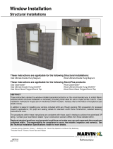
Ruskin ELF6375DXD Owner's manual

Type
Owner's manual

Ruskin ELF6375DXD is a heavy-duty louver system designed to withstand wind loads of up to 100PSF. It is ideal for use in commercial and industrial applications where high wind resistance is required. The louvers are made of aluminum and are available in a variety of sizes and finishes. The system is easy to install and can be mounted on a variety of substrates, including wood, metal, and concrete.

Ruskin ELF6375DXD is a heavy-duty louver system designed to withstand wind loads of up to 100PSF. It is ideal for use in commercial and industrial applications where high wind resistance is required. The louvers are made of aluminum and are available in a variety of sizes and finishes. The system is easy to install and can be mounted on a variety of substrates, including wood, metal, and concrete.

ELF6375DXD Installation Guide ALL STATED SPECIFICATIONS ARE SUBJECT TO CHANGE WITHOUT NOTICE OR OBLIGATION. © Ruskin November 2022
Page 1
AUTHORITY IN AIR CONTROL
ELF6375DXD
(100PSF Option)
Installation Guide
PRE-ASSEMBLY INSTRUCTIONS:
ASSEMBLY PROCEDURE:
1. Remove louvers & accessories from shipping containers & inspect for damage. Single section units will be shipped fully assembled.
Multi-section units will be shipped in shipping sections to be assembled at the job site. Large multi section units may be packaged
in more than one shipping crate.
2. Care must be taken when handling components. Lift louver sections carefully by the supports or frames. Avoid lifting by louver
blades. Do not apply excessive force to any point of the section. Lift at multiple points, if necessary to avoid deformation or
racking of components.
3. Inspect louvers & components after removal from containers. Verify that all components & fasteners are accounted for. Report
any shortages immediately to Ruskin manufacturing.
4. Inspect the openings that the louvers will be installed in. Verify that the openings are square & that the unit will fit prior to
installation.
5. Contact your local Ruskin representative if you have questions pertaining to this installation or other field modifications.
6. Ensure that you have received ship loose parts & a box with hardwares.
1. If installing an extended sill (with end dams) in the opening. Install the sill pan in between the sections if the louver is single
section wide & multi-section high. Install sill pan with lap strips if the louver is multi section wide & high. (As shown in exploded
detail) make sure to apply sealant at the location where gutters meet prior to installation of louvers.
2. Locate ship loose hardware required for louver multi-section Assemblies.
3. Position the louver sections faced down on a level, non-abrasive surface in the configuration they will be assembled in. Reference
the tag numbers on each section to ensure the sections are in correct order.
4. Refer to appropriate exploded details for splice hardware identification & location. Now fasten the sections together at frames,
support splices. (Supports are pre-drilled at plant for ease).
5. If perimeter clips or continuous angles are to be installed, locate & anchor them in the opening. (Reference clip angle installation
guide for instructions).
6. Level the louver assembly both horizontally & vertically in the opening using shims. (Shims not provided by Ruskin).
7. Position the louver in the opening so that the desired sealant joint will be maintained around the perimeter of louver.
8. After louver is secured, install backer rod & sealant around louver perimeter. (Sealant not provided by Ruskin).
LOUVER LIFTING INSTRUCTIONS
DO NOT LIFT
BY GRABBING
THE BLADES
USE
LIFTING
LUGS
LIFT
FROM
SIDE OF
LOUVER
DO NOT LIFT
BY HAND
GRABBING
THE BLADES
LIFTING CLIP
SCREEN
TYP.
TYP.
LIFTING CLIP
SCREEN
ELF6375DXD Installation Guide ALL STATED SPECIFICATIONS ARE SUBJECT TO CHANGE WITHOUT NOTICE OR OBLIGATION. © Ruskin November 2022
Page 2
2X1 MULTI SECTION INSTALLATION
2X1 MULTI SECTION EXPLODED VIEW
ISOMETRIC REAR VIEW
MULTI SECTION LOUVER ASSEMBLY
ISOMETRIC FRONT VIEW (SEALANT / CAULK INFORMATION)
CAULK GUN
APPLY SEALANT AT VISIBLE
MULLIONS(NOT PROVIDED
BY RUSKIN)
SEALANT AROUND
PERIMETER
(NOT PROVIDED
BY RUSKIN)
APPLY A BEAD OF CAULK ALONG THE BASE OF
OPENING & THEN PLACE THE SILL PAN UPON IT.
(NOT PROVIDED BY RUSKIN)
SECTION F-F
Dim "B"
(L.D.)
SECTION D-D
Dim
"B" + 3.00"
1.50"
typ. FLG.
1.50" typ. FLG.
Dim "B"
(l.D.)
DETAIL A
MULTI LAP STRIP SEALANT INFO.
BOTTOM OF SILL PAN
OPTION EXTENDED SILL
- LAP STRIP (SHIP LOOSE)
OPTION EXTENDED SILL WITH
END DAMS(SHIP LOOSE)
SEALANT
TOP OF SILL PAN
OPTION EXTENDED SILL -
LAP STRIP (SHIP LOOSE)
OPTION EXTENDED SILL WITH
END DAMS (SHIP LOOSE)
SEALANT
ELF6375DXD Installation Guide ALL STATED SPECIFICATIONS ARE SUBJECT TO CHANGE WITHOUT NOTICE OR OBLIGATION. © Ruskin November 2022
Page 3
SECTION Q-Q
Ref detail V and X
For H.V.B.S attachment detail
Ref detail W and Y
for mullion attachment detail
Ref detail T, U and AA
For attachment clip angle installation
DETAIL R
Attachment Clip Angle Installation @ Head Frame
(Wood/Metal/Concrete)
(Sill frame shown similar)
DETAIL T
Attachment Clip Angle Installation @ Jamb Frame
(Wood/Metal/Concrete/12”CMU)
L.D.
.38" max.
.38" max.L.D.
Ref wall fastener table
(11) (N.I.C.)
Ref wall fastener table
(11) (N.I.C.)
28
3" typ. from ends
21" max. C-C
32
38
(1) on each side of
HVBS/mullion support
(6” LG.)
38 6 per clip angle
2 per clip angle
Substrate
(N.I.C.)
Substrate
(N.I.C.)
Min. edge dist.
(Ref table 11)
Min. edge dist.
(Ref table 11)
Substrate
depth
Substrate depth
DETAIL V
H.V.B.S. Connection Detail
(Wood/Metal/Concrete)
DETAIL W
Mullion Connection Detail
(Wood/Metal/Concrete)
32
38
21
Varies per louver height
Structural support varies
as per louver height
32
38
39
6.00" typ.
3.50"
1.00"
6 per angle
(1) on each
side of support
38 6 per angle
1 per angle 1.00” 1.00”
15” LG.
1 on each side
of HVBS 2 at
head, 2 at sill
2" from ends.
4" max. C-C
(1) on each
side of support
.50”
.50”
Varies per louver height
S.S.D. S.S.D.
.13" typ. exp. gap
.13" typ. exp. gap
6.00" typ.
4.63" screen dim.
6 per angle
2" from ends.
8" max. C-C
(1) on each side
of mullion support
DETAIL Y
Mullion Connection Detail @ CMU
DETAIL X
HVBS Connection Detail @ CMU
S.S.D. S.S.D.
5.75”
Structural support varies as per
louver height
2" from ends. 13
8" max. C-C
3.500"
blade brace
6 per angle
1 per angle
.50"
.50"
(1) on each side
of mullion support
1 on each side
of HVBS 2 at
head, 2 at sill
39
13
35
36
38
*See table 2 for wall type and wall
depth requirement for Standard or
Reverse Angle Installation
100PSF UNLIMITED WIDTH BY 90” HIGH ASSEMBLY AND METHODS OF ATTACHMENT TO VARIOUS STRUCTURE
ELF6375DXD Installation Guide ALL STATED SPECIFICATIONS ARE SUBJECT TO CHANGE WITHOUT NOTICE OR OBLIGATION. © Ruskin November 2022
Page 4
(Sill frame shown similar)
DETAIL S
Reverse Clip Angle Installation @ Head Frame
(Wood/Metal/Concrete)
6 per clip angle
.38" max.
L.D.
Ref wall fastener
table(11) (N.I.C.)
Substrate
(N.I.C.)
Substrate
Depth
Substrate
Depth
Min. edge dist.
(Ref table 11)
(1) on each side of
HVBS/mullion support
3" typ. from ends
21" max. C-C
DETAIL U
Reverse Clip Angle Installation @ Jamb Frame
(All substrates except 6" CMU)
2 per clip angle
.38" max.
L.D.
Substrate
depth
Ref wall fastener table
(11) (N.I.C.)
Substrate (N.I.C.)
Min. edge dist.
(Ref table 11)
38
29
37
38
DETAIL AA
Double Angle Installation @ Jamb Frame
(Grout Filled CMU)
DETAIL Z
Attachment Clip Angle Installation @ Head Frame CMU only
(Sill frame shown similar)
.38" max.S.S.D.
1 per angle
15”LG.
Ref wall fastener table
(11)(N.I.C.)
Ref wall fastener table
(11) (N.I.C.)
Substrate
(N.I.C.)
Substrate (N.I.C.)
.38" max.
L.D.
Min. edge dist.
(Ref table 11)
Min. edge dist.
(Ref table 11)
1 per clip angle
3" typ. from ends
21" max. C-C (2” LG.)
3" typ. from ends
21" max. C-C (4” LG.)
2 per angle
Substrate
depth
(1) on each side of
HVBS/mullion support
(6” LG.)
6 per angle
36
33
38
34
40
35
39
38
100PSF UNLIMITED WIDTH BY 90” TALL MULLION MID SPAN CONNECTION DETAILS
TABLE 13 - ELF6375DXD - DEFAULT INSTALLATION TYPE - PERIMETER INSTALL
SUBSTRATE
TYPE
WALL
DEPTH
RANGE
INSTALL
TYPE LOCATION REFERENCE
SHEET
SUBSTRATE
TYPE
WALL
DEPTH
RANGE
INSTALL
TYPE LOCATION REFERENCE
SHEET
WOOD
6” - 9 1/2” REVERSE
ANGLE
HEAD/SILL DETAIL S
GROUT
FILLED
CMU
6” DOUBLE
ANGLE
HEAD/SILL DETAIL Z
JAMBS DETAIL U JAMBS DETAIL AA
> 9 1/2” STANDARD
ANGLE
HEAD/SILL DETAIL R
>6” - 11”
DOUBLE
ANGLE HEAD/SILL DETAIL Z
JAMBS DETAIL T REVERSE
ANGLE JAMBS DETAIL U
STEEL &
ALUMINUM
6” - 8” REVERSE
ANGLE
HEAD/SILL DETAIL S
> 11”
DOUBLE
ANGLE HEAD/SILL DETAIL Z
JAMBS DETAIL U STANDARD
ANGLE JAMBS DETAIL T
> 8” STANDARD
ANGLE
HEAD/SILL DETAIL R
JAMBS DETAIL T
CONCRETE
6” - 9 1/2” REVERSE
ANGLE
HEAD/SILL DETAIL S
JAMBS DETAIL U
> 9 1/2” STANDARD
ANGLE
HEAD/SILL DETAIL R
JAMBS DETAIL T
ELF6375DXD Installation Guide ALL STATED SPECIFICATIONS ARE SUBJECT TO CHANGE WITHOUT NOTICE OR OBLIGATION. © Ruskin November 2022
Page 5
100PSF UNLIMITED WIDTH X UNLIMITED HEIGHT
SECTION G-G
Dim "A" (l.D.) Max 96" W
32.00" max. 32.00" max. 32.00" max.
6" typ. From ends,
18" max. C-C
L.D. /S.S.D.
L.D. /S.S.D.
4.50”
2.88”
20
DETAIL J
DETAIL Q
Horizontal mullion connection detail
(Bolt attaching at head/sill not shown for clarity)
ASSEMBLY "B" - 100PSF WINDLOAD - JAMB ONLY ATTACHMENT
Max. Ship Section - 96.000" W X 60.000" H
SECTION H-H
SECTION J-J
DETAIL K
Alternate Customer Connection Detail
(Screen not shown for clarity)
Note: for heights over 90" tall, multisection assemblies are required
to have an additional structure provided by other. The design of that
structure will be the responsibility of the engineer of record
H
H
JJ
Ref detail K alternate
customer connection detail
Ref detail
alternatecustomer
connection detail
Ref detail for attachment
clip angle installation
Dim "B1"
(S.S.D.)
Dim "B2"
(S.S.D.)
Dim "B"
(L.D.)
Dim "B1"
(S.S.D.)
A-1
A-2
A-3
A-1
A-2
A-3
Dim "B1"
(S.S.D.)
Max 60" Tall
Dim "B2"
(S.S.D.)
Max 60" Tall
Dim "B3"
(S.S.D.)
Max 60" Tall
Dim "A" (l.D.)
Max. 96" wide
Dim "A" (l.D.)
Max. 96" wide
.38" typ. exp. gap
Dim "B"
(L.D.)
Alternate attachment (by others)
.38" typ. Exp. Gap
ELF6375DXD Installation Guide ALL STATED SPECIFICATIONS ARE SUBJECT TO CHANGE WITHOUT NOTICE OR OBLIGATION. © Ruskin November 2022
Page 6
100PSF UNLIMITED WIDTH X UNLIMITED HEIGHT
DETAIL M
Attachment Clip Angle Installation @ Jamb Frame
(Wood/Metal/Concrete/ 8", 10" & 12" CMU)
DETAIL N
Double Angle Installation @ Jamb Frame
(6" CMU only)
DETAIL P
Reverse Clip Angle Installation
(Wood/Metal/Concrete/ 8", 10" & 12" CMU)
Min. edge dist.
(Ref table 10)
Min. edge dist.
(Ref table 10)
L.D. / S.S.D..38" max. L.D. / S.S.D..38" max.
Substrate
depth "D"Substrate
depth "D"Substrate
depth "D"
.38" max.L.D. / S.S.D.
2 per clip
28
30
40
38 31
38
3" typ.
from ends.
6" max. C-C
Ref wall fastener
table (10) (N.I.C.)
Min. edge dist.
(Ref table 10)
Ref wall fastener
table (10) (n.I.C.)
Ref wall fastener
table (10) (N.I.C.)
2" typ. From
ends, 6.500"
max. C-C
2" typ.
From ends,
3" max. C-C
Cont.
Substrate
(N.I.C.)
Substrate
(N.I.C.)
Cont. Substrate
(N.I.C.)
29
38
3" typ.
from ends.
6" max. C-C
2 per clip
ELF6375DXD - PARTS LIST FOR STANDARD CONSTRUCTION
ITEM # DESCRIPTION REF. DWG. PART #
13 SCR 10 X 1.0 HWH TEK - 380430941
20 SPL KIT 2 X 4 X .125 PLATE W/4 #10 X 1 TEK 85-021546-00B 360437326
21 FSNR KIT 3/8-16 X 3.00” LG. BOLT FW LOCKNUT - 360500675
28 CLIP ANG 2 X 2 X 1/4 X 2 LG AL (W/2 .25 X .63 SLOTS) 85-022012-00B 360502443
29 CLIP ANG 2 X 4 X .25 X 2 LG CNTR SUNK TBD TBD
30 CLIP ANGLE - CMU INSTALL - FORMED, CONT. 85-023257-00B 800501158
31 CLIP ANGLE - CMU INSTALL, 4 X 3 X 1/4 THK. X CONT. 85-023258-00B 342379M00
32 ALTERNATE ATTACHMENT CLIP ANGLE, 6” LG. 85-023260-00B 36523600
33 CLIP ANGLE - CMU INSTALL - FORMED, 2” LG 85-023250-00B VARIES
34 CLIP ANGLE - CMU INSTALL, 4 X 3 X 1/4 THK. X 4” LG. 85-023253-00B 36523500
35 CLIP ANGLE - CMU INSTALL - FORMED, 6” LG 85-023252-00B VARIES
36 STRUCTURAL ANGLE - CMU INSTALL, 6 X 4 X 3/8 THK. X 15” LG. 85-023251-00B 36523000
37 CLIP ANG 2 X 4 X .25 X 6” LG CNTR SUNK TBD TBD
38 SCR 10 X 1.5 HWH TEK - 380430830
39 FSNR KIT 3/8-16 X 2” LG BOLT FW LOCKNUT - 360437319
40 FSNR KIT 1/4-20 X 1.5” LG BOLT FW LOCKNUT - 360437314
TABLE
ELF6375DXD Installation Guide ALL STATED SPECIFICATIONS ARE SUBJECT TO CHANGE WITHOUT NOTICE OR OBLIGATION. © Ruskin November 2022
Page 7
TABLE
TABLE 11 - ELF6375DXD 100PSF - WALL FASTENER TABLE (N.I.C.) UNLIMITED WIDTH BY 90” H - PERIMETER CONNECTION
SUBSTRATE
TYPE
MIN. SUBSTRATE
REQUIREMENTS LOCATION FASTENER TYPE MIN.
EMBEDMENT
MIN. EDGE
DISTANCE
(STANDARD/
REVERSE)
MIN. WALL DEPTH
STANDARD
ANGLE
REVERSE
ANGLE
WOOD SPECIFIC GRAVITY
= 0.4
JAMB 1/4” Ø BOLT, WASHER
& LOCKNUT N/A 2 1/2” 9 1/2” 6”
HEAD/SILL 3/8” Ø A307 BOLT,
WASHER & LOCKNUT N/A 2 1/2” 9 1/2” 6”
STEEL &
ALUMINUM
STEEL - MIN. 14 GA
ALUM. - MIN. 1/8”
THICK
JAMB 1/4” Ø A307 BOLT OR
TEK SCREW N/A 1” 8” 6”
HEAD/SILL 3/8” Ø A307 BOLT,
LOCKNUT & 1” WASHER N/A 1” 8” 6”
CONCRETE
3000 PSI MIN.
COMPRESSIVE
STRENGTH
JAMB 1/4” Ø X 2 1/4” HILTI KWIK
CON II+ W / WASHER 1 3/4” 2 1/2” 9 1/2” 6”
HEAD/SILL 3/8” Ø HILTI KWIK BOLT
TZ EXPANSION ANCHORS 2 1/2” 3 1/2” 10 1/2” 6 1/2”
GROUT FILLED
CMU (SINGLE
ANGLE)
ASTM C-90 BLOCK,
1500 PSI GROUT
COMP. STRENGTH.
JAMB
(SINGLE
ANGLE)
1/4” Ø X 2 1/2” HILTI
KWIK HUS EZ W / WASHER 1 5/8” 4” 11” 8”
JAMB
(DOUBLE
ANGLE)
1/4” Ø X 1 1/4” HILTI
KWIK CON II+ (2) PER CLIP 1” 3” 6” -
HEAD/SILL 3/8” Ø HILTI KWIK BOLT
III EXPANSION ANCHORS 2 1/2” 4” 6” -
TABLE 10 - ELF6375DXD 100PSF - WALL FASTENER TABLE (N.I.C.) UNLIMITED BY UNLIMITED - JAMB ONLY CONNECTION
SUBSTRATE
TYPE
MIN. SUBSTRATE
REQUIREMENTS FASTENER TYPE MIN.
EMBEDMENT
MIN. EDGE
DISTANCE
(STANDARD/
REVERSE)
MIN. WALL DEPTH
STANDARD
ANGLE
REVERSE
ANGLE
WOOD SPECIFIC GRAVITY = 0.4 1/4” Ø BOLT, A307
WASHER & LOCKNUT N/A 2 1/2” 9 1/2” 6”
STEEL &
ALUMINUM
STEEL - MIN. 14 GA
ALUM. - MIN. 1/8” THICK
1/4” Ø A307 BOLT OR
TEK SCREW N/A 1” 8” 6”
CONCRETE 3000 PSI MIN.
COMPRESSIVE STRENGTH
1/4” Ø X 2 1/4” HILTI KWIK
CON II+ W / WASHER 1 3/4” 2 1/2” 9 1/2” 6”
GROUT FILLED
CMU (SINGLE
ANGLE)
ASTM C-90 BLOCK, 1500 PSI
GROUT COMP. STRENGTH.
1/4” Ø X 2 1/2” HILTI KWIK
HUS EZ W / WASHER 1 5/8” 4” 11” 8”
GROUT FILLED
CMU (DOUBLE
ANGLE)
ASTM C-90 BLOCK, 1500 PSI
GROUT COMP. STRENGTH
1/4” Ø X 1 1/4” HILTI
KWIK CON II+ 1” 3” 6” -
ELF6375DXD Installation Guide ALL STATED SPECIFICATIONS ARE SUBJECT TO CHANGE WITHOUT NOTICE OR OBLIGATION. © Ruskin November 2022
Page 8
TABLE 12 - ELF6375DXD - DEFAULT INSTALLATION TYPE - JAMB ONLY INSTALL
SUBSTRATE TYPE WALL DEPTH RANGE INSTALL TYPE REFERENCE SHEET
WOOD
6” - 9 1/2” REVERSE ANGLE DETAIL P
> 9 1/2” STANDARD ANGLE DETAIL M
STEEL &
ALUMINUM
6” - 8” REVERSE ANGLE DETAIL P
> 8” STANDARD ANGLE DETAIL M
CONCRETE
6” - 9 1/2” REVERSE ANGLE DETAIL P
> 9 1/2” STANDARD ANGLE DETAIL M
GROUT FILLED
CMU
6” - 8” DOUBLE ANGLE DETAIL N
> = 8” - 11” REVERSE ANGLE DETAIL P
> 11” STANDARD ANGLE DETAIL M
3900 Doctor Greaves Road
Grandview, MO 64030
Website: www.ruskin.com
Phone: (816) 761-7476
AUTHORITY IN AIR CONTROL
LINKS TO IMPORTANT DOCUMENTS
Document Title
Limited Warranty Document
TABLE
  • Page 1 1
  • Page 2 2
  • Page 3 3
  • Page 4 4
  • Page 5 5
  • Page 6 6
  • Page 7 7
  • Page 8 8

Ruskin ELF6375DXD Owner's manual

Type
Owner's manual

Ruskin ELF6375DXD is a heavy-duty louver system designed to withstand wind loads of up to 100PSF. It is ideal for use in commercial and industrial applications where high wind resistance is required. The louvers are made of aluminum and are available in a variety of sizes and finishes. The system is easy to install and can be mounted on a variety of substrates, including wood, metal, and concrete.

Ask a question and I''ll find the answer in the document

Finding information in a document is now easier with AI