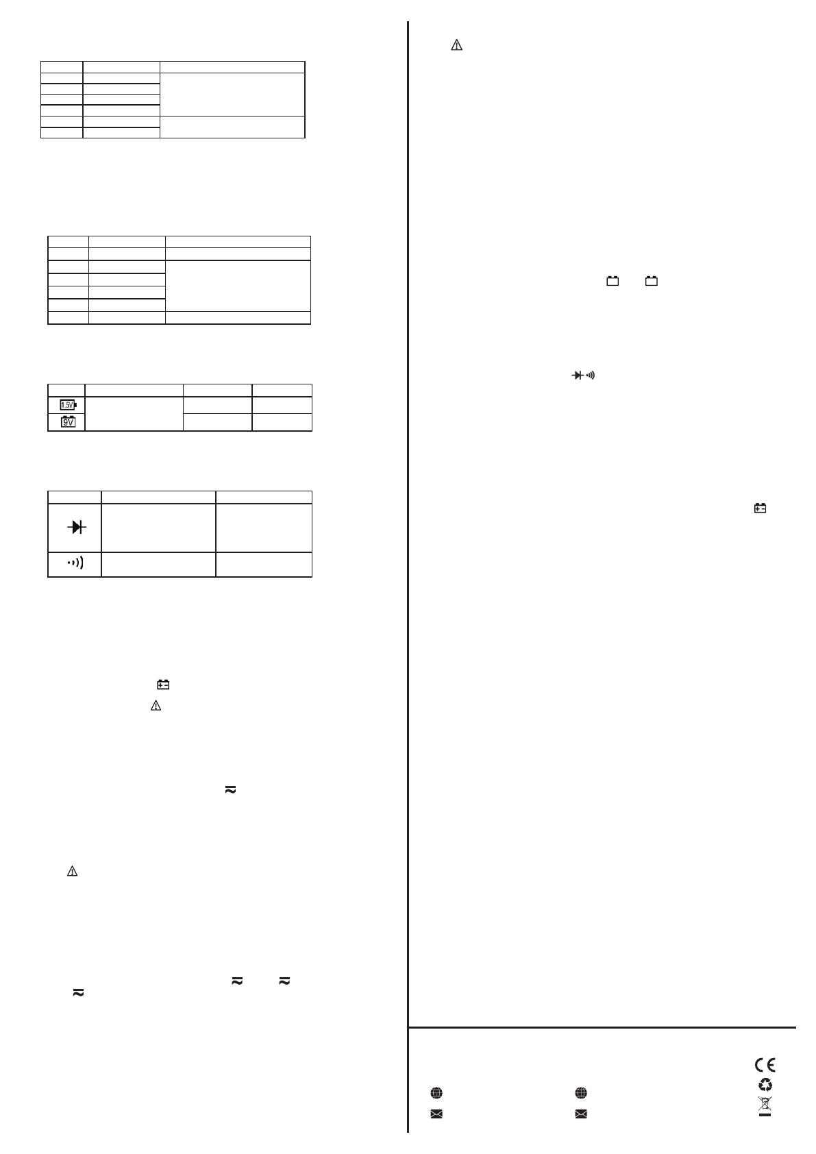
Range Resolution Accuracy
200Ω 0.1Ω
±(1.0% of rdg + 3 digits)
2kΩ
1Ω
20kΩ 10Ω
±(1.0% of rdg + 2 digits)
200kΩ
100Ω
2MΩ
1kΩ
20MΩ
10kΩ
±(1.5% of rdg + 3 digits)
Resistance
* Overload protection: 600V DC or AC rms
Range Accuracy Load current Resolution
±(5.0% of rdg + 5 digits)
Approx. 50mA 1mV
Approx. 10mA
10mV
Battery Test
* Overload protection: 250mA/600V Fast Fuse
Diode and Audible continuity test
Range
Description Test Condition
Display read approximately
Forward DC current
forward voltage of diode
approx. 0.5mA
Reversed DC voltage
approx. 2.2V
Built-in buzzer sounds if
Open circuit voltage
resistance is less than 50Ω
approx. 2V
* Overload protection: 600V DC or AC rms
Operating Instructions
Attention before operation
1. Check battery. When the battery voltage drops below a proper
operation range, the “ ” symbol will appear on the LCD display .
and the battery needs to be replaced.
2. Pay attention to the “ ” besides the input jack which shows that .
the input voltage or current should be within the specified value.
3. The range switch should be positioned to desired range for
measurement before operation.
Measuring DC & AC Voltage
1. Connect the black test lead to COM jack and the red to VΩmA jack.
2. Set the rotary switch at the desired “V ” range position, it .
shows symbol for testing DC voltage, if you want to test AC
voltage, push “SELECT” button switch.
3. Connect test leads across the source or load under measurement.
4. You can get the voltage reading from LCD. The polarity of the red
lead connection will be indicated along with the DC voltage value.
Note:
1. “ ” means you can't input the voltage more than 600V, . .
it's possible to show higher voltage, but it may damage the
inner circuit.
2. Be cautious against shock when measuring high Voltage.
Measuring DC & AC Current
1. Connect the black test lead to COM jack and the red to the
VΩmA jack for a maximum 200mA current , for a maximum
2A or 10A current, move the red lead to the 10A jack.
2. Set the rotary switch at the desired “uA ” & “mA ” & . .
“A ” range position, it shows symbol for testing DC current, if .
you want to test AC current, push “SELECT” button switch.
3. Connect test leads in series with the load under m easurement.
4. You can get the amperage reading from LCD. The polarity of the red lead
connection will be indicated along with the DC current value.
Note:
1. When the value scale to be measured is unknown b eforehand, set the
range selector at the highest position.
2. When only “OL” is displayed, it indicates over-range situation and the
higher range has to be selected.
3. “ ” means the socket mA's maximum current is 250mA and 10A's maximum .
current is 10A, over 250mA or 10A current can be protected by the fast fuse.
4. On the 10A range, the measuring time should be less than 10 seconds to
prevent precision from affecting by circuit heating.
Measuring Resistance
1. Connect the black test lead to COM jack and the red to VΩmA jack.
2. Set the rotary switch at the desired “Ω” range position.
3. Connect test leads across the resistance under measurement.
4. You can get the resistance reading from LCD.
Note: Max. input overload: 600V rms<10sec
1. For measuring resistance above 1MΩ, the meter may take a few seconds to
stabilize.
2. When the input is not connected, i.e. at open circuit, the figure 'OL' will be
displayed for the over-range condition.
3. When checking in-c ircuit r esistance, be sure the circuit under t est has a ll
power removed and that all capacitors have been fully discharged.
Battery Testing
1. Connect the black test lead to COM jack and the red to VΩmA jack.
2. Set the rotary switch at the desired “ ” or “ ” range position to test . .
1.5V or 9V battery.
3. Connect the red test lead to the positive of the battery and the black test
lead to the negative of the battery.
4. You can get battery voltage reading from LCD.
Diode & Audible continuity Testing
1. Connect the black test lead to COM jack and the red to VΩmA jack.
2. Set the rotary switch at the “ ” range position, push “ SELECT” t o .
choose Diode or Audible continuity measurement.
3. On diode range, connect the test leads across the diode under
measurement, display shows the approx. forward bias voltage of this diode.
4. On Audible continuity range, connect the test leads to two point of circuit,
if the resistance is lower than approx. 50Ω, the buzzer sounds.
Note:
Make sure all the power is removed and all capacitors need to be d ischarged
under this measurement.
Battery replacement
1. When the battery voltage drops below the proper operation r ange t he “ ” .
symbol will appear on the LCD display and the battery need to replaced.
2. Before replacing the battery, set the selector switch to “OFF” position and
remove the test leads from the terminals. Open the cover of the battery
cabinet with a suitable screwdriver.
3. Replace the old battery with the same type of battery (AA R6P 1.5V×2).
4. Close the cover of the battery cabinet and fasten the screw.
Fuse replacement
1. This meter is provided with a 250mA/600V fast fuse to protect the battery
test and the current measuring circuits which measure up to 200mA, with a
10A/600V fuse to protect the 10A range.
2. Ensure the meter is not connected to any external circuit, set the selector
switch to “OFF” position and remove the test leads from the terminals. Open
the cover of the battery cabinet with a suitable screwdriver.
3. Replace the old fuse with the same type and rating: 6×32mm 250mA/600V
fast fuse or 6×32mm 10A/600V fast fuse.
4. Close the cover of the battery cabinet and fasten the screw.
Maintenance
1. You must replace the test leads if the insulation is broken and internal wire is
exposed, use the same test leads with the same specifications.
2. Use only a moist fabric or small amount of detergent but not chemical
solution for cleaning.
3. Do not use the meter before the back cover is properly closed and screw
secured. If any problems are encountered, stop operation immediately and
send the meter for maintenance.
4. Please remove the battery when not using for a long time.
Accessories
1. Test Leads: electric rating 600V 10A. If the test leads need to be replaced,
you must use a new one which should meet EN 61010-01 standard, rated
CAT III 600V, 10A or better.
2. Operator's Manual
Range Resolution
Accuracy
200μA
0.1μA
2000μA
1μA
±(1.5% of rdg + 3 digits)
20mA
10μA
200mA
100μA
2A
1mA
±(2.5% of rdg + 5 digits)
10A
10mA
AC Current
* AC True RMS
* Overload protection: 250mA/600V Fast Fuse
10A/600V Fast Fuse, 10A up to 10 seconds
* Frequency Range: 40 to 2kHz
1.5V 9V
www.major-tech.com www.majortech.com.au
sales@major-tech.com info@majortech.com.au
MAJOR TECH (PTY) LTD
South Africa Australia


