Electrolux WE1100P Smart 12 kg Washing Machine Installation guide
- Type
- Installation guide

Installation manual
Washer Extractor
WE1100P
Original instructions
0020508979/EN
2022.01.04


Contents
Contents
1 Attention.............................................................................................................................................5
2 Installation Manual ..............................................................................................................................5
3 Safety Precautions ..............................................................................................................................5
3.1 General safety information..........................................................................................................6
3.2 Commercial use only..................................................................................................................6
3.3 Ergonomics certification .............................................................................................................6
3.4 Symbols....................................................................................................................................7
4 Warranty terms and exclusions.............................................................................................................8
5 Technical Data ....................................................................................................................................9
5.1 Drawing ....................................................................................................................................9
5.2 Technical data .........................................................................................................................10
5.3 Connections ............................................................................................................................10
6 Installation ........................................................................................................................................ 11
6.1 Install the bottom cover plate .................................................................................................... 11
6.2 Transportation Bolts ................................................................................................................. 11
6.3 Removing Transportation Bolts .................................................................................................12
6.4 Recycling instruction for packaging ...........................................................................................13
6.5 Activating the prewash program ................................................................................................14
6.6 Coin Mode...............................................................................................................................14
6.7 Install the Coin Meter (coin operated models).............................................................................15
6.8 Install the Blocking Plate (Non-coin models)...............................................................................15
6.9 Setting ....................................................................................................................................16
6.10 Floor .......................................................................................................................................16
7 Water Connections............................................................................................................................17
8 Drain Connection ..............................................................................................................................18
9 Connection of External Liquid Supply Signals ......................................................................................19
10 Electrical Connections .......................................................................................................................20
11 Function Checks ...............................................................................................................................21
12 Preventive Maintenance ....................................................................................................................22
12.1 Daily .......................................................................................................................................22
12.2 Every Third Month....................................................................................................................22
13 Disposal information ..........................................................................................................................23
13.1 Disposal of appliance at end of life ............................................................................................23
13.2 Disposal of packing..................................................................................................................23
The manufacturer reserves the right to make changes to design and component specifications.


Installation manual 5
1 Attention
Four transportation bolts are installed in the rear of the machine, to protect the suspension and tub assembly from
damage during shipment.
Remove all four bolts and plastic tubes through which the bolts pass before operating the machine!!
See instructions later in this manual.
2 Installation Manual
Warning
All operating and maintenance procedures shown in this manual must be followed at the frequency specified for
proper operation of your machine.
3 Safety Precautions
• Servicing shall be carried out only by authorized personnel.
• Only authorized spare parts, accessories and consumables shall be used.
• Only use detergent intended for water-wash of textiles. Never use dry cleaning agents.
• The machine shall be connected with new water hoses. Re-used water hoses must not
be used.
• The machine's door lock must under no circumstances be bypassed.
• If the machine develops a fault, this must be reported to the person in charge as soon
as possible. This is important both for your safety and that of others.
• DO NOT MODIFY THIS APPLIANCE.
• When performing service or replacing parts, the power must be disconnected.
• When the power is disconnected, the operator must see that the machine is discon-
nected (that the plug is removed and remains removed) from any point to which he has
access. If this is not possible, due to the construction or installation of the machine, a
disconnection with a locking system in the isolated position shall be provided.
• In accordance with the wiring rules: mount a multi-pole switch prior to the machine to
facilitate installation and service operations.
• If different rated voltages or different rated frequencies (separated by a /) are stated at
the machine data plate, instructions for adjusting the appliance for operation at the re-
quired rated voltage or rated frequency are stated in the installation manual.
• The openings in the base, shall not be obstructed by a carpet.
• Maximum load volume: 12 kg.
• A-weighted emission sound pressure level at working stations:
– Wash: <62 dB(A).
– Extraction: <72 dB(A).
• Maximum inlet water pressure: 800 kPa / 116 psi
• Minimum inlet water pressure: 50 kPa / 8 psi
• Additional requirements for the following countries; AT, BE, BG, HR, CY, CZ, DK, EE,
FI, FR, DE, GR, HU, IS, IE, IT, LV, LT, LU, MT, NL, NO, PL, PT, RO, SK, SI, ES, SE, CH,
TR, UK:
– The appliance can be used in public areas.

6Installation manual
– This appliance can be used by children aged from 8 years and above and persons
with reduced physical, sensory or mental capabilities or lack of experience and knowl-
edge if they have been given supervision or instruction concerning use of the appliance
in a safe way and understand the hazards involved. Children shall not play with the ap-
pliance. Cleaning and user maintenance shall not be made by children without
supervision.
• Additional requirements for other countries:
– This appliance is not intended for use by persons (including children) with reduced
physical, sensory or mental capabilities, or lack of experience and knowledge, unless
they have been given supervision or instruction concerning use of the appliance by a
person responsible for their safety. Children should be supervised to ensure that they
do not play with the appliance.
– This appliance is intended to be used in household and similar applications such as:
(IEC 60335-2-7) staff kitchen areas in shops, offices and other working environments,
farm houses, by clients in hotels, motels and other residential type environments, bed
and breakfast type environments, areas for communal use in blocks of flats or in
launderettes.
3.1 General safety information
The machine is only intended for water-wash use.
Do not hose down the machine with water.
In order to prevent damage to the electronics (and other parts) that may occur as the result of condensation, the ma-
chine should be placed in room temperature for 24 hours before being used for the first time.
3.2 Commercial use only
The machine/machines covered by this manual is/are made for commercial and industrial use only.
3.3 Ergonomics certification
The human body is designed for movement and activity but physical stress injuries as a result of static and repetitive
movements or unfavorable working postures may occur.
The ergonomic features of your product, the ones which may influence your physical and cognitive interaction with it,
have been assessed and certified.
A product which exhibits ergonomic features, in fact, shall fulfil specific ergonomic requirements, belonging to three
different areas: Polytechnic, Biomedical and Psychosocial (usability and satisfaction).
For each of these areas, specific tests with real users have been performed. The product was therefore compliant
with the ergonomic acceptability criteria requested by the standards.
In case several machines are managed by the same operator the repetitive movements will increase and as a conse-
quence of this the related biomechanical risk will increase exponentially.
The possible postural risks are the interaction with the door handle in case the machine is not placed on a base.
Follow the below recommendations to avoid, as much as possible, operators acquiring bodily injury.
• Place the machine on a base instead of directly on the floor so that the operator does not need to bend his/her
back unnecessarily when loading and unloading.
Minimum suggested height of bases is 300 mm.
• Make sure there are suitable trolleys or baskets for loading, unloading and transportation.
• Organize job rotation in the working place in the case several machines are managed by the same operator.

Installation manual 7
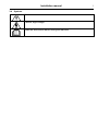
3.4 Symbols
Caution
Caution, high voltage
Read the instructions before using the machine

8Installation manual
4 Warranty terms and exclusions
If the purchase of this product includes warranty coverage, warranty is provided in line with local regulations and sub-
ject to the product being installed and used for the purposes as designed, and as described within the appropriate
equipment documentation.
Warranty will be applicable where the customer has used only genuine spare parts and has performed maintenance
in accordance with Electrolux Professional user and maintenance documentation made available in paper or elec-
tronic format.
Electrolux Professional strongly recommends using Electrolux Professional approved cleaning, rinse and descaling
agents to obtain optimal results and maintain product efficiency over time.
The Electrolux Professional warranty does not cover:
• service trips cost to deliver and pick up the product;
• installation;
• training on how to use/operate;
• replacement (and/or supply) of wear and tear parts unless resulting from defects in materials or workmanship re-
ported within one (1) week from the failure;
• correction of external wiring;
• correction of unauthorized repairs as well as any damages, failures and inefficiencies caused by and/or resulting
from;
– insufficient and/or abnormal capacity of the electrical systems (current/voltage/frequency, including spikes and/
or outages);
– inadequate or interrupted water supply, steam, air, gas (including impurities and/or other that does not comply
with the technical requirements for each appliance);
– plumbing parts, components or consumable cleaning products that are not approved by the manufacturer;
– customer’s negligence, misuse, abuse and/or non-compliance with the use and care instructions detailed within
the appropriate equipment documentation;
– improper or poor: installation, repair, maintenance (including tampering, modifications and repairs carried out
by third parties not authorized third parties) and modification of safety systems;
– Use of non-original components (e.g.: consumables, wear and tear, or spare parts);
– environment conditions provoking thermal (e.g. overheating/freezing) or chemical (e.g. corrosion/oxidation)
stress;
– foreign objects placed in- or connected to- the product;
– accidents or force majeure;
– transportation and handling, including scratches, dents, chips, and/or other damage to the finish of the product,
unless such damage results from defects in materials or workmanship and is reported within one (1) week of deliv-
ery unless otherwise agreed;
• product with original serial numbers that have been removed, altered or cannot be readily determined;
• replacement of light bulbs, filters or any consumable parts;
• any accessories and software not approved or specified by Electrolux Professional.
Warranty does not include scheduled maintenance activities (including the parts required for it) or the supply of
cleaning agents unless specifically covered within any local agreement, subject to local terms and conditions.
Check on Electrolux Professional website the list of authorized customer care.

Installation manual 9
5 Technical Data
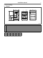
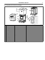
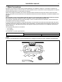
5.1 Drawing
A
B
D E
C
1 2
5
3 4
6
7
8
9
fig.W01595
1 Power line
2 Air vent for safety
3 Cold water
5 Drain
6 Coin meter
7Control panel
8 Detergent container
9 Door
ABCDE
mm 1098 584 310 686 765
inch 43 1/4 23 12 3/16 27 30 1/8

10 Installation manual
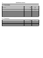
5.2 Technical data
Weight, net kg
lbs
136
300
Drum volume litres
ft3
100
3.5
Drum diameter mm
inch
556
21 7/8
Drum speed during wash rpm 45
Drum speed during extraction rpm 1050
G-factor, max. 300
Heating: Electricity kW 2.0
Sound power/pressure level at extraction* dB(A) 72
Sound power/pressure level at wash* dB(A) 62
* Sound power levels measured according to ISO 60704.
5.3 Connections
Water valves DN
BSP
20
3/4”
Recommended water pressure kPa 200–600
Continuous operating pressure kPa 50–800
Capacity at 300 kPa l/min 20
Drain valve ⌀outer mm 60
Draining capacity l/min 25

Installation manual 11
6 Installation
For safety, two people should install this product.
Leave the machine on the transport pallet until it can be placed in the final, prepared position.
First remove all the packing materials. Upon opening of the package, water drops may be seen in the plastic bag and
the drum. This is a normal phenomenon resulting from water tests in the factory.
Note!
1. A bottom cover plate is wrapped in the top of the packing material.
2. Be careful while handling the bottom cover.
3. Remove all anti-scratch film from the washer.
6.1 Install the bottom cover plate
1. Lay the package carton on the ground.
2. Lay the washer slowly down on its back on the package carton.
3. Install the bottom cover on the bottom of the machine using the 8 screws provided in the accessories bag.
4. Lift the washer to the upright position.
fig.W01596
6.2 Transportation Bolts
The washer is fitted with transportation bolts to prevent internal damage during transportation.
Transportation bolts must be removed before using the washer.

12 Installation manual
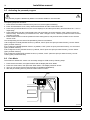
6.3 Removing Transportation Bolts
1. Unscrew the 4 bolts with a wrench. Remove the lower 2 bolts first, then the upper two. One of bolts retains the
power cord of the washer to prevent operating without removing bolts.
2. Remove the bolts and the red plastic sleeves to release the power cord. Keep the 4 bolts and sleeves for future
use.
Note!
If transportation bolts and sleeves are not removed, it may cause severe vibration, noise and malfunction,
as well as damage to the machine.
Note!
When the washer is transported the transportation bolts and the sleeves must be reinstalled.
3. Close the 4 holes with the caps supplied.
1
2
4
4
3
3
5
fig.W01597
1 Brace
2 Cap
3 Bolt
4 Sleeve
5Screws

Installation manual 13
6.4 Recycling instruction for packaging
3
1
2
4
5
6
7
8
9
10
11
12
13
14
15
fig.X02414
Fig. Description Code Type
1 Carton box BC Corrugated Paper
2 Packaging box sticker Synthetic paper Paper
3 Bar code sticker Synthetic paper Paper
4 Wrapping film LDPE Plastics
5 Front corner protection EPS EPS
6 Back corner protection EPS EPS
7 Top protection EPS EPS
8 Packing bottom EPS EPS
9 Pallet Plywood Wood
10 PET tape PET Plastics
11 Packaging strap PP 5 Plastics
12 Brace, transport Steel Metal
13 Bolt, transport Steel Metal
14 Packing bolt gasket Steel Metal
15 Packing bolt plastic sleeve PA6 Plastic

14 Installation manual
6.5 Activating the prewash program
The prewash program is disabled by default. You need to enable it in service mode.
The opening steps are as follows:
1. Press the service switch inside the money box once, all the lights are flashing.
2. Press The Start button once, Heavy and Extra Rinse flash and the screen shows "SE".
3. Press Heavy and Extra Rinse once, the screen displays 00, and then press Heavy and Extra Rinse as "-" and "+"
respectively.
4. Press Extra Rinse until the screen displays 80, and press Start, the screen displays “P2of” (does not open pre-
wash function). Press Heavy or Extra Rinse once, “P2of” change to “P2on”, and then pre-wash function of COLD
program is opened.
5. Press the Start button to exit the prewash function setting switch, and press the service switch once to exit the
service mode.
The corresponding service code of the prewashing function is as follows:
1.80 Configure the COLD prewash function, by default, “P2oF” (does not open pre-wash function), can set “P2oN”
(open pre-wash function)
2.81 Configure the WARM prewash function, by default, “P2oF” (does not open pre-wash function), can set “P2oN”
(open pre-wash function)
3.82 Configure the HOT prewash function, by default, “P2oF” (does not open pre-wash function), can set “P2oN”
(open pre-wash function)
4.83 Configure the DELICATE prewash function, by default, “P2oF” (does not open pre-wash function), can set
“P2oN” (open pre-wash function)
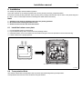
6.6 Coin Mode
The machine is default OPL mode. You can easily change to COIN mode by following steps:
1. Press the service switch, the lights will flash and the display will show "8888".
2. Press the "Cold" button, then press the "Start" button. The display will show "00.00".
3. Then you can set the price through the button (Cold/Warm/Hot/Delicate).
4. After the price setting is done, press the "Start" button to save it.
1
fig.W01598
1 Service Switch

Installation manual 15
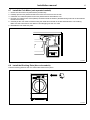
6.7 Install the Coin Meter (coin operated models)
1. Unlock the coin meter lock plate with the provided key.
2. Partially open the lock plate and slide to the left to remove it from the console.
3. Install the coin meter faceplate into the lock plate and then assemble the coin.
4. Plug the coin meter(s) into COIN (White) harnesses inside the washer. (Detailed wiring methods are described in
the service manual).
5. Carefully fix the coin meter harnesses using the cable ties mounted on the bracket behind the coin meter(s).
Make sure the harnesses do not obstruct coins dropping into the coin vault.
6. Reinstall the coin meter lock plate.
fig.W01599
6.8 Install the Blocking Plate (Non-coin models)
Push the blocking plate into the coin vault until the tabs lock in place.
fig.W01600

16 Installation manual
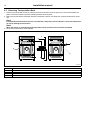
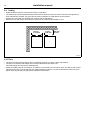
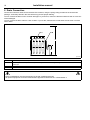
6.9 Setting
• Please install the machine close to a floor drain or open drain.
• The machine should be well positioned and make sure that there is plenty of room for the users and personnel
when maintenance needed. The figure shows minimum distance to a wall and/or other machines.
• At least 20 inches (500 mm) between the machine and the wall behind.
• Minimum 1 inch (25 mm) to next machine if more than one machine is installed in a row.
70 mm /
2 3/4 inch
70 mm /
2 3/4 inch
500 mm /
20 inch
fig.W01601
6.10 Floor
• The floor must be smooth and hard. Do not install the machine on carpet or other soft material.
• The floor must hold the total weight of the machine filled with water and a load.
This static weight is 416 pounds (188 kilograms).
• Adjust the levelling legs of the machine, as needed, to ensure that it is level front to back, and side to side, and so
that all four feet are in contact with the floor. After leveling the machine, use the enclosed locknut wrench tool to
tighten each leg's locking nut against the underside of the washer.

Installation manual 17
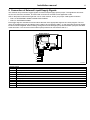
7 Water Connections
Plumbing: This machine is approved for all UK applications as suitable for category 5. The product is listed in the
WRAS regulations advisory scheme directory and is suitable for direct connection to mains drinking water. No special
plumbing arrangements e.g. break tanks are required.
Water Council approved double check valves should be fitted in between the stopcocks and the water inlet hoses.
All inlet connections to the machine are to be fitted with manual shut-off valves and filters, to facilitate installation and
servicing.
Note!
The inlet filter screens are provided inside the machine's connection fittings. Water pipes and hoses should
be flushed clean before installation. After installation, hoses should hang in gentle arcs.
The machine is equipped with two water inlet fittings, one for hot water and one for cold water. Those need only be
hand tightened when properly assembled.
If hoses are difficult to assemble, or leak after assembly, check that the hoses have been assembled with the proper
orientation and have a garden-hose washer in each swivel fitting. Your water heater should supply hot water at a min-
imum temperature of 120 degrees Fahrenheit (49 degrees Celsius) and a maximum of 170 degrees Fahrenheit (77
degrees Celsius).
The required water pressure is as follows:
• min: 50 kPa
• max: 800 kPa
recommended: 30-90 PSI (200-600 kPa)
Water Type Water Connection
1 2
Cold and Hot Cold Hot
Note!
If there is no hot water port in your environment, it's enough to connect only the cold water inlet with water.
C H
12
fig.W01602

18 Installation manual
8 Drain Connection
Connect the machine's drain hose to the back of the washer, using the spring clamp provided in the accessories
package. Avoid sharp bends in the hose which may prevent proper draining.
You can connect the drain hose to a sewer stand pipe. If you do this, make sure that the outlet hose will not come out
of the stand pipe.
You can connect the drain outlet to a sink or basin. If you do this, make sure the outlet hose will not come out of the
sink or basin.
A
B
C D
fig.W01603
A 47.2 inches (120 centimeters) maximum
B 30 inches (76 centimetres) minimum OR placed directly in a drain basin or trough making sure the end of the hose is never
submerged.
C Machine
D Drain outlet hose
Electrical installation must be carried out by licensed, qualified personnel!
All optional equipment connected must be EMC-approved to EN 61000-6-1 or EN 61000-6-3.

Installation manual 19
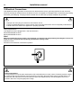
9 Connection of External Liquid Supply Signals
The machine can provide two "trigger signals" for external liquid supply injector pumps. The signals are 220-240V
AC, 5A max, and must, therefore, be routed and connected in accordance with applicable codes.
CN5 on the power module at the right-rear corner of the machine, and to your pumps. With signals as follows:
• CN5-1,2: DETERGENT SIGNAL AND BLEACH SIGNAL
• CN5-3,4: SOFTENER SIGNAL
Each trigger signal is activated for 30 seconds at the start of the appropriate segment of a wash program. The con-
nector of the detergent pump and bleach pump needs to be connected to CN5-1, 2, their terminals cannot be separa-
ted and must be integrated. When washing, the signals from the detergent pump and the bleach pump are activated
at the same time. The connector of the softener pump needs to be connected to CN5-3, 4.
1
2
3
4
fig.W01605
CN INPUT SHOW
CN1 Motor Thermal Protector
CN3 Power input
CN4 Heating tube
CN5 Liquid supply signals connector
CN6 Inlet valve
CN7 Drain pump
CN13 Door lock
CN23 Heating temperature sensor
CN22 Communication with display PCB
CN17 Motor tachometer

20 Installation manual
10Electrical Connections
This appliance must be grounded. In the event of an electrical short circuit, grounding reduces the risk of electric
shock by providing an escape wire for the electric current. This appliance is equipped with a cord having a grounding
wire with a grounded plug. The plug must be inserted into an outlet that is properly installed and grounded.
• Improper use of the plug can result in a risk of electric shock.
• Consult a qualified electrician or service person if the grounding instructions are not completely understood or
if doubt exists as to whether the appliance is properly grounded.
Wiring Requirements:
This appliance must be plugged into a 10A 220-240 VOLT,
50HZ GROUNDED OUTLET.
60HZ GROUNDED OUTLET.
Note!
Where a standard two-prong outlet is encountered, it is the personal responsibility and obligation of the con-
sumer to have it replaced with a properly grounded three prong outlet.
Extension Cords:
DO NOT use an extension cord with this product.
fig.W01606
Power Interruptions
Occasionally there may be power interruptions due to thunderstorms or other causes. Following a power outage,
the machine will resume operation at the point where it was when the power failed. During a power failure, the
loading door will UNLOCK a few minutes after the drum has stopped turning. This allows garments to be re-
moved in the event of a prolonged power outage.
Page is loading ...
Page is loading ...
Page is loading ...
Page is loading ...
-
 1
1
-
 2
2
-
 3
3
-
 4
4
-
 5
5
-
 6
6
-
 7
7
-
 8
8
-
 9
9
-
 10
10
-
 11
11
-
 12
12
-
 13
13
-
 14
14
-
 15
15
-
 16
16
-
 17
17
-
 18
18
-
 19
19
-
 20
20
-
 21
21
-
 22
22
-
 23
23
-
 24
24


Electrolux WE1100P Smart 12 kg Washing Machine Installation guide
- Type
- Installation guide
Ask a question and I''ll find the answer in the document
Finding information in a document is now easier with AI
Related papers
-
Electrolux WE170PP User manual
-
-
-
-
-
Electrolux WE170P User manual
-
-
-
-