jbc Ds360 Micro Desoldering Iron User manual

Category
Soldering irons
Type
User manual

The JBC DS360 Micro Desoldering Iron is a lightweight and ergonomic tool designed for precise desoldering tasks. It features a powerful vacuum pump that quickly and effectively removes solder from components, making it ideal for rework and repair applications. The tool's temperature can be easily adjusted, allowing it to be used with a wide range of solder alloys. Additionally, the DS360 is ESD safe, ensuring that it will not damage sensitive electronic components.

The JBC DS360 Micro Desoldering Iron is a lightweight and ergonomic tool designed for precise desoldering tasks. It features a powerful vacuum pump that quickly and effectively removes solder from components, making it ideal for rework and repair applications. The tool's temperature can be easily adjusted, allowing it to be used with a wide range of solder alloys. Additionally, the DS360 is ESD safe, ensuring that it will not damage sensitive electronic components.

DS360
Micro Desoldering Iron
INSTRUCTION MANUAL
Micro Desoldering Iron ............................................................ 1 unit
C360004 already inserted
Manual ............................ 1 unit
Ref. 0028149
Packing List
The following items are included:
This manual corresponds to the following reference:
- DS360-A
DS360 Accessories
Ref. 0010259
Cleaning Rods .............. 1 unit
Ref. 0008466
Tips .......................... 10 units
Ref. C360002 (x5)
C360004 (x5)
Cleaning Brush ......... 1 unit
Ref. 0008297
Union Flanges ......... 2 units
Ref. 0 0113 5 6
Solder Collector ..... 2 units
Ref. 0008467
Filter ........................... 2 units
Ref. 0008473
2
CD-S
CD-B
CA
CS
CDE-S
CDE-B
CP
OK
TOOL
EARTHING FUSE
AUX
USE ONLY WITH A 250 V FUSE
OK
ºC
ºFA
OK
Language
Mode




Exit



Language
Mode




Exit
Language
Mode




Exit




Maximum temp
Minimum temp 200ºC
350ºC
8886698
PIN
Sound

Date&Time

02/06/2021, 15:01
ºC
On
O
Red limit 40%
0.5s/div
Ok to reset soldering Ref.
20
16
12
8
4
355
350
345
340
335
180
Sleep
W% ºC
Time
Energy
C245907 Ref.
2.3s
14W·s
---
---
ºC
19:29
Selected
Min 200 Max 400
350
º
C
0.5s/div
Ok to reset soldering Ref.
20
16
12
8
4
355
350
345
340
335
180
Sleep
W% ºC
Time
Energy
C210009 Ref.
2.3s
14W·s
---
---
ºC
19:29
Selected
Min 200 Max 400
350
º
C
0.5s/div
Ok to set up soldering Ref.
20
16
12
8
4
355
350
345
340
335
350
Sel. temp. 350ºC
W% ºC
Time
Energy
C245907 Ref.
2.3s
14W·s
---
---
ºC
19:29
0.5s/div
Ok to set up soldering Ref.
20
16
12
8
4
355
350
345
340
335
350
Sel. temp. 350ºC
W% ºC
Time
Energy
C210009 Ref.
2.3s
14W·s
---
---
ºC
19:29
0.5s/div
Ok to reset soldering Ref.
20
16
12
8
4
355
350
345
340
335
350
Sel. temp. 350ºC
W% ºC
Time
Energy
C245907 Ref.
2.3s
14W·s
2.4s
13W·s
ºC
95%
0.5s/div
Ok to reset soldering Ref.
20
16
12
8
4
355
350
345
340
335
350
Sel. temp. 350ºC
W% ºC
Time
Energy
C210009 Ref.
2.2s
18W·s
2.4s
17W·s
ºC
94%
0.5s/div
Ok to reset soldering Ref.
20
16
12
8
4
355
350
345
340
335
350
Sel. temp. 350ºC
W% ºC
Time
Energy
C245907 Ref.
2.3s
14W·s
---
---
ºC
19:29
0.5s/div
Ok to reset soldering Ref.
20
16
12
8
4
355
350
345
340
335
350
Sel. temp. 350ºC
W% ºC
Time
Energy
C245907 Ref.
2.3s
14W·s
1.3s
8W·s
ºC
38%
19:29
19:29
19:29
0.5s/div
Ok to reset soldering Ref.
20
16
12
8
4
355
350
345
340
335
350
Sel. temp. 350ºC
W% ºC
Time
Energy
C210009 Ref.
2.3s
14W·s
---
---
ºC
19:29
0.5s/div
Ok to reset soldering Ref.
20
16
12
8
4
355
350
345
340
335
350
Sel. temp. 350ºC
W% ºC
Time
Energy
C210009 Ref.
2.3s
14W·s
1.3s
8W·s
ºC
38%
19:29
1s/div
150 Time
C210-008 Ref..
4.5s ---
ºC
SOLDERING JOINT INFO 1/3
Sel. temp.
Cartridge
Time
Max temp
Min temp
Energy
Result
Last Ref. Diff.
350ºC 350ºC
C245907
2.4s
350ºC
335ºC
13W·s
2.3s
C245907
-2%
350ºC +0%
340ºC -1%
14W·s +29%
95%
1s/div
150 Time
C210-008 Ref..
4.5s ---
ºC
SOLDERING JOINT INFO 1/3
Sel. temp.
Cartridge
Time
Max temp
Min temp
Energy
Result
Last Ref. Diff.
350ºC 350ºC
C210009
2.4s
350ºC
335ºC
13W·s
2.3s
C210009
-2%
350ºC +0%
340ºC -1%
14W·s +29%
95%
C21
00
09
Cartridge
Language
Mode




Exit
Cartridge
Language
Mode




Exit
Hiberna�on

ºC
25% 75%
Power C245907
50%
19:29
325
º
CSel. temp.
325ºC
25% 75%
Power C245907
50%
Sleep

ºC

25% 75%
Power C245907
50%
19:2919:29
Hiberna�on

ºC
25% 75%
Power 
50%
19:29
325
º
CSel. temp.
325ºC
25% 75%
Power 
50%
Sleep

ºC

25% 75%
Power 
50%
19:2919:29
Desoldering process
When desoldering, use a tip with a diameter larger than the pad being desoldered. This will achieve
maximum suction and thermal efficiency.
The vacuum pump will continue to run for a few seconds. This makes sure that the vacuum
circuit is completely empty. If there are any solder remains left on a terminal, just resolder it
with fresh solder and repeat the desoldering operation.
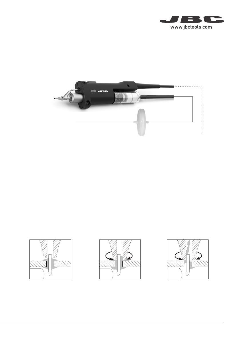
Connection
1. Apply the tip so that it fits
over the component terminal.
2. When the solder liquefies,
gently rotate the tip so that the
terminal can be lifted off.
3. Then press the vacuum
pump button long enough to
suck up the solder.
Micro Desoldering Iron
Ref. DS360-A
to Desoldering Module
to Stand
Suction Filter
Ref. 0821830
Supplied with
Desoldering Module
3
40 mm
50 mm
60 mm
80 mm
100 mm
130 mm 130 mm
para manuales - color gris
200 mm
300 mm
T210 / T245 / T470
NT115
AN115
AM120
AT420
NP115
PA120
HT420
HT470
DS360
DR560
AP250
AL250
SF280
JT-TA
TE-TB
NH-A
PA120
PA120
AL250
0.9-1 Ø0.9-1 Ø0.9-1 Ø
AL250
0.9-1 Ø0.9-1 Ø0.9-1 Ø
0.9-1 0.9-1 Ø0.9-1 Ø
NH
NH
NH
AP250
AP250
AP250 AP250
AP250
AP250
T210 / T245 / T470
NT115
AN115
AM120
AT420
NP115
PA120
HT420
HT470
DS360
DR560
AP250
AL250
SF280
JT-TA
TE-TB
NH-A
PA120
PA120
AL250
0.9-1 Ø0.9-1 Ø0.9-1 Ø
AL250
0.9-1 Ø0.9-1 Ø0.9-1 Ø
0.9-1 0.9-1 Ø0.9-1 Ø
NH
NH
NH
AP250
AP250
AP250 AP250
AP250
AP250
T210 / T245 / T470
NT115
AN115
AM120
AT420
NP115
PA120
HT420
HT470
DS360
DR560
AP250
AL250
SF280
JT-TA
TE-TB
NH-A
PA120
PA120
AL250
0.9-1 Ø0.9-1 Ø0.9-1 Ø
AL250
0.9-1 Ø0.9-1 Ø0.9-1 Ø
0.9-1 0.9-1 Ø0.9-1 Ø
NH
NH
NH
AP250
AP250
AP250 AP250
AP250
AP250
T210 / T245 / T470
NT115
AN115
AM120
AT420
NP115
PA120
HT420
HT470
DS360
DR560
AP250
AL250
SF280
JT-TA
TE-TB
NH-A
PA120
PA120
AL250
0.9-1 Ø0.9-1 Ø0.9-1 Ø
AL250
0.9-1 Ø0.9-1 Ø0.9-1 Ø
0.9-1 0.9-1 Ø0.9-1 Ø
NH
NH
NH
AP250
AP250
AP250 AP250
AP250
AP250
Changing Heating Element
1. Remove the filter before changing the heating
element.
2. Remove the fixing screw and take out the
heating element.
Note: For the following operations, turn off the station or disconnect the tool and wait until the
tool temperature drops to room temperature.
Desoldering Iron Maintenance
3. Insert the new heating element into the tool. 4. Tighten the fixing screw and insert the filter.
4
T210 / T245 / T470
NT115
AN115
AM120
AT420
NP115
PA120
HT420
HT470
DS360
DR560
AP250
AL250
SF280
JT-TA
TE-TB
NH-A
PA120
PA120
AL250
0.9-1 Ø0.9-1 Ø0.9-1 Ø
AL250
0.9-1 Ø0.9-1 Ø0.9-1 Ø
0.9-1 0.9-1 Ø0.9-1 Ø
NH
NH
NH
AP250
AP250
AP250 AP250
AP250
AP250
T210 / T245 / T470
NT115
AN115
AM120
AT420
NP115
PA120
HT420
HT470
DS360
DR560
AP250
AL250
SF280
JT-TA
TE-TB
NH-A
PA120
PA120
AL250
0.9-1 Ø0.9-1 Ø0.9-1 Ø
AL250
0.9-1 Ø0.9-1 Ø0.9-1 Ø
0.9-1 0.9-1 Ø0.9-1 Ø
NH
NH
NH
AP250
AP250
AP250 AP250
AP250
AP250
T210 / T245 / T470
NT115
AN115
AM120
AT420
NP115
PA120
HT420
HT470
DS360
DR560
AP250
AL250
SF280
JT-TA
TE-TB
NH-A
PA120
PA120
AL250
0.9-1 Ø0.9-1 Ø0.9-1 Ø
AL250
0.9-1 Ø0.9-1 Ø0.9-1 Ø
0.9-1 0.9-1 Ø0.9-1 Ø
NH
NH
NH
AP250
AP250
AP250 AP250
AP250
AP250
Changing Iron Filter
1. Remove the tube from the filter. 2. Remove the filter form the tool.
3. Insert a new filter (ref. 0008473) into the tool
and mount the tube onto the filter.
5
40 mm
50 mm
60 mm
80 mm
100 mm
130 mm 130 mm
para manuales - color gris
200 mm
300 mm
T210 / T245 / T470
NT115
AN115
AM120
AT420
NP115
PA120
HT420
HT470
DS360
DR560
AP250
AL250
SF280
JT-TA
TE-TB
NH-A
PA120
PA120
AL250
0.9-1 Ø0.9-1 Ø0.9-1 Ø
AL250
0.9-1 Ø0.9-1 Ø0.9-1 Ø
0.9-1 0.9-1 Ø0.9-1 Ø
NH
NH
NH
AP250
AP250
AP250 AP250
AP250
AP250
T210 / T245 / T470
NT115
AN115
AM120
AT420
NP115
PA120
HT420
HT470
DS360
DR560
AP250
AL250
SF280
JT-TA
TE-TB
NH-A
PA120
PA120
AL250
0.9-1 Ø0.9-1 Ø0.9-1 Ø
AL250
0.9-1 Ø0.9-1 Ø0.9-1 Ø
0.9-1 0.9-1 Ø0.9-1 Ø
NH
NH
NH
AP250
AP250
AP250 AP250
AP250
AP250
T210 / T245 / T470
NT115
AN115
AM120
AT420
NP115
PA120
HT420
HT470
DS360
DR560
AP250
AL250
SF280
JT-TA
TE-TB
NH-A
PA120
PA120
AL250
0.9-1 Ø0.9-1 Ø0.9-1 Ø
AL250
0.9-1 Ø0.9-1 Ø0.9-1 Ø
0.9-1 0.9-1 Ø0.9-1 Ø
NH
NH
NH
AP250
AP250
AP250 AP250
AP250
AP250
T210 / T245 / T470
NT115
AN115
AM120
AT420
NP115
PA120
HT420
HT470
DS360
DR560
AP250
AL250
SF280
JT-TA
TE-TB
NH-A
PA120
PA120
AL250
0.9-1 Ø0.9-1 Ø0.9-1 Ø
AL250
0.9-1 Ø0.9-1 Ø0.9-1 Ø
0.9-1 0.9-1 Ø0.9-1 Ø
NH
NH
NH
AP250
AP250
AP250 AP250
AP250
AP250
T210 / T245 / T470
NT115
AN115
AM120
AT420
NP115
PA120
HT420
HT470
DS360
DR560
AP250
AL250
SF280
JT-TA
TE-TB
NH-A
PA120
PA120
AL250
0.9-1 Ø0.9-1 Ø0.9-1 Ø
AL250
0.9-1 Ø0.9-1 Ø0.9-1 Ø
0.9-1 0.9-1 Ø0.9-1 Ø
NH
NH
NH
AP250
AP250
AP250 AP250
AP250
AP250
Cleaning Solder Collector
1. Remove the filter before cleaning the solder
collector.
3. Use the cleaning brush (ref. 0008297) to
clean the solder collector inside or replace it for
a new one.
2. Take out the solder collector with the metal
solder retention.
4. Insert the solder collector with the metal
solder retention into the heating element.
Note: For this operations, turn off the station or disconnect the tool and wait until the tool
temperature drops to room temperature.
5. Mount the filter onto the tool.
6
$¡
%¡
C360-001
ØA= 1 mm (0.04 in)
ØB= 0,6 mm (0.02 in)
Ømax. pin= 0,4 mm (0.02 in)
C360-002
ØA= 1,2 mm (0.05 in)
ØB= 0,8 mm (0.03 in)
Ømax. pin= 0,6 mm (0.02 in)
C360-004
ØA= 1,6 mm (0.06 in)
ØB= 1,2 mm (0.05 in)
Ømax. pin= 1 mm (0.04 in)
C360-007
ØA= 1,9 mm (0.08 in)
ØB= 1,4 mm (0.06 in)
Ømax. pin= 1,2 mm (0.05 in)
C360-006
ØA= 3 mm (0.12 in)
ØB= 1,5 mm (0.06 in)
Ømax. pin= 1,3 mm (0.05 in)
C360-003
ØA= 1,4 mm (0.06 in)
ØB= 1 mm (0.04 in)
Ømax. pin= 0,8 mm (0.03 in)
Compatible Tips
The DS360 uses C360 tips.
Find the model that best suits your needs in www.jbctools.com
C360-011
ØA= 1 mm (0.04 in)
ØB= 0,6 mm (0.02 in)
C360-013
ØA= 1,4 mm (0.06 in)
ØB= 1 mm (0.04 in)
C360-012
ØA= 1,3 mm (0.05 in)
ØB= 0,8 mm (0.03 in)
C360-014
ØA= 1,6 mm (0.06 in)
ØB= 1,2 mm (0.05 in)
7
40 mm
50 mm
60 mm
80 mm
100 mm
130 mm 130 mm
para manuales - color gris
200 mm
300 mm
T210 / T245 / T470
NT115
AN115
AM120
AT420
NP115
PA120
HT420
HT470
DS360
DR560
AP250
AL250
SF280
JT-TA
TE-TB
NH-A
PA120
PA120
AL250
0.9-1 Ø0.9-1 Ø0.9-1 Ø
AL250
0.9-1 Ø0.9-1 Ø0.9-1 Ø
0.9-1 0.9-1 Ø0.9-1 Ø
NH
NH
NH
AP250
AP250
AP250 AP250
AP250
AP250
T210 / T245 / T470
NT115
AN115
AM120
AT420
NP115
PA120
HT420
HT470
DS360
DR560
AP250
AL250
SF280
JT-TA
TE-TB
NH-A
PA120
PA120
AL250
0.9-1 Ø0.9-1 Ø0.9-1 Ø
AL250
0.9-1 Ø0.9-1 Ø0.9-1 Ø
0.9-1 0.9-1 Ø0.9-1 Ø
NH
NH
NH
AP250
AP250
AP250 AP250
AP250
AP250
T210 / T245 / T470
NT115
AN115
AM120
AT420
NP115
PA120
HT420
HT470
DS360
DR560
AP250
AL250
SF280
JT-TA
TE-TB
NH-A
PA120
PA120
AL250
0.9-1 Ø0.9-1 Ø0.9-1 Ø
AL250
0.9-1 Ø0.9-1 Ø0.9-1 Ø
0.9-1 0.9-1 Ø0.9-1 Ø
NH
NH
NH
AP250
AP250
AP250 AP250
AP250
AP250
Changing Tips
1. To remove the tip, use a pair of flat-nosed
pliers, twist the tip and pull.
2. To fasten the tip, do not hold it on the spring
clamp. Place the pliers directly in front of the
spring.
Note: This operation should be done while the tip is hot and at a minimum temperature of
250°C, so that any tin left inside is still molten.
Cleaning Tips
Choose the cleaning rod diameter
according to the tip size. Put the rod at
the tip, gently move it back and forth while
turning it slightly.
The tip hole should be periodically cleaned.
Note: Let the tool cool down before performing this operation.
Tip Care
To prevent tip oxidation cover tip with solder tin when not in use. Note: Do not press the vacuum
pump button while tinning the desoldering tip, as the fumes given off by the flux would quickly block
the ducts and the air filter.
8
Maintenance
Before carrying out maintenance, always switch the device off and disconnect it from the mains. Allow
the equipment to cool down.
- Use a damp cloth to clean the tool. Alcohol can only be used to clean the metal parts.
- Periodically check that the metal parts of the tool and stand are clean so that the station can detect
the tool status.
- Maintain tip surface clean and tinned prior to storage in order to avoid tip oxidation.
Rusty and dirty surfaces reduce heat transfer to the solder joint.
- Periodically check all cables and tubes.
- Replace any defective or damaged pieces. Use original JBC spare parts only.
- Repairs should only be performed by a JBC authorized technical service.
9
40 mm
50 mm
60 mm
80 mm
100 mm
130 mm 130 mm
para manuales - color gris
200 mm
300 mm
It is imperative to follow safety guidelines to protect health and prevent electric
shock, injury, fire or explosions.
Safety
- Do not use the tool for any purpose other than soldering or rework. Incorrect use may cause fire.
- Do not work on electrically live parts.
- The tool should be placed in the stand when not in use in order to activate the sleep mode. The
soldering tip or nozzle, the metal part of the tool and the stand may still be hot even when the station
is turned off. Handle with care, including when adjusting the stand position.
- Do not leave the appliance unattended when it is on.
- It is necessary to turn the station off before changing tips.
- Heat can cause inflamable products to ignite even when out of sight.
- Be careful with the remains of liquid tin. Avoid flux coming into contact with skin or eyes to prevent
irritation.
- Utmost care must be taken with liquid tin waste which can cause burns.
- Be careful with the fumes produced when soldering.
- Keep your workplace clean and tidy. Wear appropriate protection glasses and gloves when working
to avoid personal harm.
- This appliance can be used by children over the age of eight as well as persons with reduced physical,
sensory or mental capabilities or lacking of experience provided that they have been given adequate
supervision or instruction concerning use of the appliance and understand the hazards involved.
Children must not play with the appliance.
- Maintenance must not be carried out by children unless supervised.
10
Notes
11
40 mm
50 mm
60 mm
80 mm
100 mm
130 mm 130 mm
para manuales - color gris
200 mm
300 mm
This product should not be thrown in the garbage.
In accordance with the European directive 2012/19/EU, electronic equipment at the end of its life must
be collected and returned to an authorized recycling facility.
Warranty
JBC’s 2 year warranty covers this equipment against
all manufacturing defects, including the replacement
of defective parts and labour.
Warranty does not cover product wear or misuse.
In order for the warranty to be valid, equipment must
be returned, postage paid, to the dealer where it was
purchased.
Get 1 extra year JBC warranty by registering here:
https://www.jbctools.com/productregistration/
within 30 days of purchase.
40 mm
50 mm
60 mm
80 mm
100 mm
130 mm 130 mm
para manuales - color gris
200 mm
300 mm
0028149-1021
DS360
Micro Desoldering Iron
Ref.: DS360-A
- Total Net Weight: 176 g / 0.39 lb
- Package Dimensions / Weight: 300 x 125 x 65 mm / 341 g
(L x W x H) 11.81 x 4.92 x 2.56 in / 0.75 lb
Complies with CE standards.
ESD safe.
Specifications
  • Page 1 1
  • Page 2 2
  • Page 3 3
  • Page 4 4
  • Page 5 5
  • Page 6 6
  • Page 7 7
  • Page 8 8
  • Page 9 9
  • Page 10 10
  • Page 11 11
  • Page 12 12

jbc Ds360 Micro Desoldering Iron User manual

Category
Soldering irons
Type
User manual

The JBC DS360 Micro Desoldering Iron is a lightweight and ergonomic tool designed for precise desoldering tasks. It features a powerful vacuum pump that quickly and effectively removes solder from components, making it ideal for rework and repair applications. The tool's temperature can be easily adjusted, allowing it to be used with a wide range of solder alloys. Additionally, the DS360 is ESD safe, ensuring that it will not damage sensitive electronic components.

Ask a question and I''ll find the answer in the document

Finding information in a document is now easier with AI