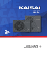
Midea M-thermal User manual

Category
Split-system air conditioners
Type
User manual

Midea M-thermal is an air source heat pump designed to provide efficient and eco-friendly heating and hot water for residential and commercial properties. Equipped with advanced inverter technology, it can adapt its output to match the heating demand, saving energy and reducing running costs. Its compact design and low noise operation make it suitable for both indoor and outdoor installation. The unit comes with a user-friendly remote controller, allowing precise temperature adjustment and various operating modes, including heating, hot water, and automatic modes.

Midea M-thermal is an air source heat pump designed to provide efficient and eco-friendly heating and hot water for residential and commercial properties. Equipped with advanced inverter technology, it can adapt its output to match the heating demand, saving energy and reducing running costs. Its compact design and low noise operation make it suitable for both indoor and outdoor installation. The unit comes with a user-friendly remote controller, allowing precise temperature adjustment and various operating modes, including heating, hot water, and automatic modes.

M-thermal Mono
ATW Heat Pump
Quick Installation Manual
3
www.freedomhp.co.uk 02380 274 833 | [email protected]
2
Contents
Preparing the unit 4
Where to install the unit 5
Heating & hot water schematic 6
Piping the unit 7
Wiring Schematic 8
How it’s going to work 10
Running the unit for the first time 11
Field settings 12
A glance of the user interface 15
Starting the unit 16
Operational data 18
Freedom Heat Pumps 19
8/10/12/14/16 kW
4/6 kW
Hydraulic System
Refrigerant System
Electric Control System
Terminal Block
8/10/12/14/16 kW4/6 kW
4 5
www.freedomhp.co.uk 02380 274 833 | [email protected]
Preparing the unit Where to install the unit
When the unit is delivered there is a blue cover over the coil, please
remove it, the remote controller is in a box at the back off the unit
Remove the right hand front cover of the unit to gain access.
To gain access to the wiring, you will need to remove the 2 x 13mm
bolts at the front to get the cover off, don’t loose them they MUST go
back in.
On the larger 8-12-14kw units, the compressor has a plate which has
to be removed prior to installation, see above. Do not remove the
metal frame the unit is bolted to, it is structural.
12/14/16 kW
Remove the
transportation support
Please remove the blue
plastic before installing
Remove the coil cover
Remove the compressor support
Unit Dimensions
4/6 kW (unit: mm)
H
8/10/12/14/16 kW (unit: mm)
I
H
J
I
E D
B
FG
C
A
E D
B
F
C
A
G
Model A B C D E F G H I J
4/6kW 1295 397 429 760 256 105 225 792 161 /
8/10/12/14/16kW 1385 482 526 760 270 160 221 945 182 81
Installing the Outdoor Unit (Boiler)
Position the outdoor unit so that the air flows into an open area, where there are no plants and animals. If the unit
is to be installed within a mile of the sea you need to have the unit coated using Blygold, ask us for details. If you are
applying for RHI and going through MCS you need to make sure the system meets MIS020.
Install the outdoor unit on a flat, stable surface, it needs to be securely mounted at least 100mm off the ground. You
can use rubber feet under the unit if you want but its not essential.
The unit must have adequate drainage, it can produce up to 6 L / hour of condensate. If you are installing the unit at
height you can install a drain pan under the unit but its best to let the unit drain into the ground.
300 or more 300 or more
300 or more
1500 or more
The space around the unit is very important, allow:
300mm to the left hand side (facing the front of the unit),
300mm to the right of the unit,
300mm to the rear of the unit and 1500mm to the front of the
unit.
6 7
www.freedomhp.co.uk 02380 274 833 | [email protected]
Heating & hot water schematic Piping the unit
Every system will have a low loss header (buffer or plate heat exchanger) in the heating circuit, there are no short cuts.
If you install the unit with no low loss header, you will void the warranty
Pump PO
Timer for
Immersion
SV1
AB
BA
Header,
Buer or
Heat
Exchanger
Z2
Z1
Extras
Heating & Hot Water
Midea unit
Feet Small
Midea adapter 1 1/4” to 1 “
2x Fibre washer 1 1/4”
2x Fibre washer 1”
2x Flexi Hoses
Robotkit ( only needed on
8-16kW units )
1x Pump
1x 28mm 3 port valve
Filter Ball
Glycol
Header
32A Isolator
2x Electric Meter Optional
Cylinder
Immersion Timer
Delivery
Install Manual
The water connections are flow at the top and the return at the top bottom, they are 1 1/4” male, we will deliver it with
an adapter to 1” male and will supply flexi hoses to fit. You must use 28mm copper or plastic pipe to connect the unit .
The pump in the unit is strong enough to push the water a maximum of 12m each way to the hot water cylinder and
The low loss header. If your pipe length is more than 12m of 28mm copper please call us first
Coding Assembly Unit
1 High voltage wire hole
2 Low voltage wire hole
3 Drainage pipe hole
4 Water outlet
5 Water inlet
4/6 kW
8~16 kW
12
435
4 5 3
2
1
8 9
www.freedomhp.co.uk 02380 274 833 | [email protected]
Note the immersion heater is not connected to the heat pump. You need to connect it to an
externally powered time clock programmed to do a 1 hour legionella cycle every week (or day) .
The 3 port valve SV1 wires from 5 live to 16 Neutral
If the valve is installed backwards terminal 5 and 6 are the opposite of each other swap wire from 5 to 6 and the valve will reverse.
The heating run signal wires from 3 to 15. The unit sends out 240V AC on terminal 15 when you send it back on terminal 3 the unit
runs in heating mode.
Pump Po heating pump after the header is wired into 10 live and 22 Neutral.
The remote controller can be wired in Cat 5 cable up to 20m long
The blue hot water cylinder sensor is delivered 10m long, it can be extended to 20m long with 1mm 2 core flex.
Wiring Schematic Wiring Schematic
Pump PO
Timer for
Immersion
SV1
Header,
Buer or
Heat
Exchanger
Z2
Z1
Extras
Wiring Schematic
SV1, the 3 port valve connects AB to A when there is no
power. The valve must be installed with A to House and B to
the cylinder.
SV1 powers AB to B for hot water mode
A to house
B to cylinder
Power Supply 240V
16A for the 4, 6, 8, and 10kW
32A for the 12, 14 and 16 kW
Run signal for
heating from UFH
or stats 240V ac
Cylinder sensor included is 10m
long, you can extend to 20m with
1mm flex.
Remote controller needs 5 core
0.1mm cable max 20m long
SV1
Pump PO
10 11
www.freedomhp.co.uk 02380 274 833 | [email protected]
How it’s going to work Running the unit for the first time
Space Heating
The heat pump has its own inbuilt weather compensation system,
it will look for a heating run signal from an external thermostat or
under floor heating system (field supplied). The unit sends out 240V
AC on terminal 15 when you send it back on terminal 3 the unit
runs in heating mode. This will come from your underfloor heating
system or your heating zone valves after the header.
Before power up
Filling it with water
Connect the water supply to the fill valve and open the valve.
Make sure the automatic air vent is open, its in the outdoor unit
inside a rubber cover top right hand side of the unit .
Fill with water pressure of approximately 2.0 bar. Remove air in
the circuit as much as possible using the air purge valves. Air in the
water circuit will cause flow errors EO and E8
Setting up the cylinder immersion heater
To insure the unit has adequate legionella protection the immersion
heater will run for 1 hour a week controlled by an external time
clock. It will run the immersion heater make sure the internal
thermostat on the immersion is set as high as possible 60°C.
Turn all thermostats down and underfloor heating off, before you
power up the heat pump.
Power up the unit and look at the
display on the outdoor unit PCB.
In the middle of the main PCB inside the right hand casing there
is a red 3 digit display, it will light up and show the current water
temperature. If nothing is displayed check the power supply to the
unit. Once it is lit up check the remote controller.
On the screen of the remote controller it will count to 100, then it
will ask you which language to use, select EN press OK. If you wait 60
seconds it will just select English as default.
If the error code E2 is displayed on the controller check the wiring
between the remote controller and unit. Redo the wiring and reset
the power.
Domestic water heating
The target tank water temperature is set on the Midea remote
controller. The Midea unit will decide when to go into HW mode it
will stop Pump Po (heating pump) the 3 port valve SV1 will power
open.
The AVV is protected
with a rubber cover.
Make sure the AAV is
open before filling the
unit.
CN11 CN7 CN30
15
3
L1
HEAT(H)
Room thermostat
15 is live
3 is heat run signal 240V AC
3-way valve SV1 Secondary heating pump P0
CN11 CN7 CN30
16
5
CN11 CN7 CN30
22
10
5
16
10
22
12 13
www.freedomhp.co.uk 02380 274 833 | [email protected]
Field settings Field settings
Initial setup
DO NOT SKIP THIS SECTION
The unit is delivered as a completely blank slate, it does not know
you want to use a hot water cylinder or that you are using an
external heating run signal. So if you just switch it on and leave you
will be back to do the job properly.
The controller will look like the image to the right.
Press and hold the UNLOCK button for 3 seconds
Press MENU press 8 times to SERVICEMAN, press OK
Enter password 234 press OK
Go to DHW MODE setting, press OK
IN DHW mode press then change it to YES press OK
Go to DISINFECT press then to NON press OK (legionella is
handled by an external immersion and time clock)
Go to 1.18 DHWHPMax and set to 60 for 200L tank or 90 for
300L tank press OK
Press BACK
Go to Heat Mode setting press OK
Go to 3.8 T1setH1 press right set to 55°C for Rads or 45°C
for UFH press OK
Go to 3.9 T1setH2 press right set to 37°C press OK
Go to 3.10 T4H press right set to -2°C press OK
Go to 3.11 T4H press right set to 15°C press OK
This is the setting for your weather compensation for heating the
water will be 55°C at -2° ambient and 37°C when its 15° ambient.
Press BACK
Go to 6 Room thermostat, press OK
Go to 6.1 Room thermostat press change to one zone
Press OK
Press Back 2 times.
You have now told the unit it has a remote thermostat, its got
weather compensation and it has a hot water cylinder.
Now you have to test to see if its tubed and wired up OK.
T1SETH1
T1S (T1S2)
T4H1 T4H2
T4
T1SETH2
Test Run
TEST RUN is used to check correct operation of the unit
Go to MENU FOR SERVICEMAN enter password 234 OK, go to
11.TEST RUN. Press OK. The following page will be displayed:
Select YES press OK
Select POINT CHECK press OK
Go to 3 way valve 1 press on off button the valve will move from
heating to DHW
Go to Pump I (pump in the heat pump) press on off, it will start,
you can see a green led on the front of the pump when its running.
Go to Pump O this is the pump after the low loss header, it will be
pumping out to the heating circuits.
When you are happy all of these work OK press BACK
If you want to force the heat pump to run go to 11.5 heat mode
running, the unit will show
After 6 minutes the compressor will start and it will heat up the
water. Note at this point the unit does not know what the valves are
doing so it will heat wherever the water is flowing. It should go to the
header, if it goes to the hot water cylinder the 3 port valve is wired
backwards swap the live cable from 5 to 6 (power off first).
To exit this mode press Back a few times to get to the normal front
screen.
11 TEST RUN
Test run is on.
Heat mode is on.
Leaving water temperature is
15°C.
OK CONFIRM
11 TEST RUN
Active the settings and
active the “TEST RUN”?
OK CONFIRM
NO YES
11 TEST RUN
OFF
OFF
OFF
OFF
OFF
ON/OFF ON/OFF
3-WAY VALVE 1
3-WAY VALVE 2
PUMP I
PUMP O
PUMP C
1/2
11 TEST RUN
OFF
OFF
OFF
OFF
OFF
ON/OFF ON/OFF
PUMPSOLAR
PUMPDHW
INNER BACKUP HEATER
TANK HEATER
3-WAY VALVE 3
2/2
14 15
www.freedomhp.co.uk 02380 274 833 | [email protected]
Field settings A glance of the user interface
Restore Factory Settings
If you mess up the controller you can restore it to factory.
The RESTORE FACTORY SETTING is used to restore all the parameters
set in the user interface to the factory setting.
Go to MENU FOR SERVICEMAN 10.RESTORE FACTORY SETTINGS.
Press OK. The following page will be displayed:
Press   to scroll the cursor to YES and press OK.
The following page will be displayed:
10 RESTORE FACTORY SETTINGS
All the settings will come back to
factory default.
Do you want to restore factory
settings?
OK CONFIRM
NO YES
Please wait…
5%
10 RESTORE FACTORY SETTINGS
Enter the menu
structure from
the home page
Navigate the
cursor on the
display/navigate
in the menu
structure/adjust
the settings
Come back to
the up level
Turn on or off the
space operation
mode or DHW
mode turn on or
off the function
in the menu
structure
Long press for
unlocking /locking
the controller
Go to the next step when programming a
schedule in the menu structure/ confirm
a selection/enter a submenu in the menu
structure
At the next scheduled action,
the desired temp. will decrease.
the desired temp.
will not change.
the desired temp.
will decrease.
the desired temp.
will increase.
ECO mode
is activated
Holiday away
/home
is activated
7
Silent mode
is activated
Tank heater is activated
The solar energy is activated
Fan coil
The floor heating
Water flow desired temp.
Radiator
Fan coil Radiator
The compressor is activated
Turn off
Turn on
OFF
Heat mode
Cool mode
Auto mode
Timer icon
Lock icon
Outdoor ambient temp.
WLAN icon
The disinfect
function is activated
Domestic hot water
ON
DHW tank temp.
Error or protection icon
OFF
ON
Weekly schedule icon
Domestic hot water
Prevent
freezing mode
is activated
Defrost mode
is activated
Smart grid icon
Smart grid
Free electricity
The pumpi is activated
Valley electricity Peak electricity
Additional heat source
Electric pipe heat source
Room desired temp.
The floor heating
16 17
www.freedomhp.co.uk 02380 274 833 | [email protected]
Unlock screen
If the icon is on the screen, the controller is locked.
The following page is displayed:
Press any key, the icon will flash. Long press the ‘’UNLOCK’’ key.
The icon will disappear, the interface can be controlled.
Setting the clock and date
Press MENU, press 6 times to SERVICE INFO press OK
Press 3 times to DISPLAY press OK
Go to TIME press then use and to set the time hours
and minutes, press OK
Go to DATE press then use and to set the day and
month, press OK
Go to Buzzer press ON / OFF to silence the noise from the
controller.
Press back a few times to get to the front screen
Starting the unit in heating mode
Press to highlight the left hand side of the controller this is the
heating side, press ON / OFF
The middle of the controller tells you what is happening now. In this
case heating (the sun) is on, so the thermostats are calling. The unit
will start the pump in 2 minutes and the compressor in 5 minutes.
Check the pipework is heating up and the header is getting warm.
MAKE SURE there is no hot water going to the cylinder.
Note if you try to change the water temperature or turn the heating
off a message shows. This unit is controlled from an external
run signal and operates using the water settings for weather
compensation you set earlier.
Starting the unit in hot water mode to
heat the cylinder
Go back to the front screen, press to highlight the right side of the
controller. This is the hot water setting.
When you highlight the DHW it tells you the DHW set temperature,
when it’s not highlighted it shows the current DHW tank
temperature. With it highlighted press ON / OFF the unit will start
heating the cylinder
Note how the middle of the controller is now showing the tap to
indicate its actually heating the tank.
Starting the unit Starting the unit
Turning on or off cooling/
heating mode is controlled by
the room thermostat.
Please turn on or off cooling/
heating mode by the room
thermostat.
CONFIRM
OK
18 19
www.freedomhp.co.uk 02380 274 833 | [email protected]
Who are
Freedom Heat
Pumps?
Freedom Heat Pumps is a wholesale distribution company for air source
heat pumps and underfloor heating systems.
We offer technical support, training, design and consultancy services
Freedom Heat Pumps was founded in 2010 and have been market
leaders in this sector with over 7500 units out in the field.
How we work
Our approach is very straightforward. If you have a set of plans or an
outline of the requirements for a project, send them to
[email protected]. From there, we will produce a heat loss
calculation in line with today’s standards, and put together a list of the kit
required at your cost price.
Alternatively, if you don’t currently have a heat pump project, but would
like to become a heat pump installer, and don’t know where to start,
contact us on 02380 274833 or email us at [email protected] and
we can set you on the correct course.
Freedom Heat PumpsOperational data
Operational data for testing the unit
This menu is for installer or service engineer reviewing the operation parameters. Here you can see everything the unit
is doing with tools.
At the home page, go to MENU OPERATION PARAMETER.
Press OK. There are six pages for the operating parameter as following. Use and to scroll.
Trouble shooting
All error codes are listed in the installation and owners manual at the back pages 70-76.
If the remote controller shows “E8” or “E0” as an error code, there is a possibility that there is air in the system, or the
water level in the system is less than the required minimum.
OPERATION PARAMETER
#01
OPERATE MODE COOL
ADDRESS
SV1 STATE ON
ONLINE UNITS NUMBER 1
SV2 STATE OFF
SV3 STATE OFF
PUMP_I ON
1/9
OPERATION PARAMETER
#01
PUMP-C OFF
ADDRESS
PUMP-S OFF
PUMP-O OFF
PUMP-D OFF
PIPE BACKUP HEATER OFF
TANK BACKUP HEATER ON
2/9
OPERATION PARAMETER
#01
T1 LEAVING WATER TEMP. 35°C
ADDRESS
WATER FLOW 1.72m
3
/h
GAS BOILER OFF
HEAT PUMP CAPACTIY 11.52kW
POWER CONSUM. 1000kWh
Ta ROOM TEMP 25°C
3/9
OPERATION PARAMETER
#01
Tw2 CIRCUIT2 WATER TEMP. 35°C
ADDRESS
TIS’ C1 CLIMATE CURVE TEMP. 35°C
T5 WATER TANK TEMP. 53°C
TIS2’ C2 CLIMATE CURVE TEMP. 35°C
TW_O PLATE W-OUTLET TEMP. 35°C
TW_I PLATE W-OUTLET TEMP. 30°C
4/9
OPERATION PARAMETER
#01
Tbt2 BUFFERTANK_LOW TEMP. 35°C
ADDRESS
IDU SOFTWARE 01-09-2019V01
Tbt1 BUFFERTANK_UP TEMP. 35°C
5/9
Tsolar 25°C
OPERATION PARAMETER
#01
COMP.CURRENT 12A
ADDRESS
COMP.FREQENCY 24Hz
ODU MODEL 6kW
COMP.RUN TIME 54 MIN
COMP.TOTAL RUN TIME 1000Hrs
EXPANSION VALVE 200P
6/9
OPERATION PARAMETER
#01
IDU TARGET FREQUENCY 46Hz
ADDRESS
FREQUENCY LIMITED TYPE 5
FAN SPEED 600R/MIN
SUPPLY VOLTAGE 230V
DC GENERATRIX VOLTAGE 420V
DC GENERATRIX CURRENT 18A
7/9
OPERATION PARAMETER
#01
TW_I PLATE W-INLET TEMP. 30°C
ADDRESS
T2 PLATE F-OUT TEMP. 35°C
TW_O PLATE W-OUTLET TEMP. 35°C
T2B PLATE F-IN TEMP. 35°C
Th COMP. SUCTION TEMP. 5°C
Tp COMP. DISCHARGE TEMP. 75°C
8/9
OPERATION PARAMETER
#01
T4 OUTDOOR AIR TEMP. 5°C
ADDRESS
TF MODULE TEMP. 55°C
T3 OUTDOOR EXCHARGE TEMP. 5°C
P1 COMP. PRESSURE 2300kPa
ODU SOFTWARE 01-09-2018V01
HMI SOFTWARE 01-09-2018V01
9/9
@freedomheatpumps
@freedomheatpump
Freedom Heat Pumps Ltd.
freedomheatpumps
www.freedomhp.co.uk
Copyright © 2020 Freedom Heat Pumps Ltd. All rights reserved. Specifications
and designs are subject to change without notice. Non-metric weights and
measurements are approximate. All data were deemed correct at time of creation.
Freedom Heat Pumps Ltd is not liable for errors or omissions. All brand, product,
service names and logos are trademarks and/or registered trademarks of their
respective owners and are hereby recognized and acknowledged.
v290920
Freedom Heat Pumps Ltd
Head Office
Unit 2 Warrior Park,
Eagle Close
Chandlers Ford,
Hampshire
SO53 4NF
Northern Office
Unit 5, Roundhouse Court,
Buckshaw Village,
Chorley,
Lancashire
PR7 7JN
Tel: 02380 274 833
www.freedomhp.co.uk
  • Page 1 1
  • Page 2 2
  • Page 3 3
  • Page 4 4
  • Page 5 5
  • Page 6 6
  • Page 7 7
  • Page 8 8
  • Page 9 9
  • Page 10 10
  • Page 11 11
  • Page 12 12
  • Page 13 13
  • Page 14 14
  • Page 15 15
  • Page 16 16
  • Page 17 17
  • Page 18 18
  • Page 19 19
  • Page 20 20

Midea M-thermal User manual

Category
Split-system air conditioners
Type
User manual

Midea M-thermal is an air source heat pump designed to provide efficient and eco-friendly heating and hot water for residential and commercial properties. Equipped with advanced inverter technology, it can adapt its output to match the heating demand, saving energy and reducing running costs. Its compact design and low noise operation make it suitable for both indoor and outdoor installation. The unit comes with a user-friendly remote controller, allowing precise temperature adjustment and various operating modes, including heating, hot water, and automatic modes.

Ask a question and I''ll find the answer in the document

Finding information in a document is now easier with AI