Neumann KH 120 II AES67 User manual

Type
User manual
georg neumann gmbh · Leipziger str. 112 · 10117 berLin · germany
teL +49 (0)30 / 41 77 24-0 · fax -50 · [email protected]om · www.neumann.com
pubL. 05/23
592856/a02
kh 120 ii aes67
kh 150 aes67
Two-way active Loudspeaker
Instruction manuaL
KH 120 II AES67 / KH 150 AES67 | 2
Studio Monitors KH 120 II AES67 and KH 150 AES67 ...........................3
Delivery includes ..........................................................3
About this manual..........................................................3
Product overview: KH 120 II AES67 ..........................................4
Product overview: KH 150 AES67 ............................................5
Setting up and connecting the loudspeaker....................................6
Preparing the loudspeakers ............................................6
Preparing the room....................................................6
Positioning the loudspeakers ...........................................7
Connecting audio signals...............................................8
Connecting a network cable for network control ..........................10
Connecting/disconnecting the loudspeaker to/from the power supply system 11
Configuring and using the loudspeaker ...................................... 11
Switching the loudspeaker on/o.......................................11
Functionality of the Neumann logo .....................................12
Switches on the SETTINGS panel .......................................13
Resetting the loudspeaker settings .....................................14
Firmware update.....................................................14
Adapting loudspeakers to the environment using the switches
on the backplate .....................................................15
Adjusting the acoustical level..........................................16
Configuring standby mode.............................................17
Customizing standby behavior . . . . . . . . . . . . . . . . . . . . . . . . . . . . . . . . . . . . . . . . . 18
Configuring AES67 network and audio settings ...............................20
Initial setup.........................................................20
Selecting the control mode and audio input..............................20
Setting up the AES67 network interface .................................21
Setting up the PTP media clock ........................................26
Setting up the connection management mode ............................28
Routing digital AES67 audio signals to the loudspeaker ...................30
Compatibility with DANTE AES67 audio streams ........................35
Cleaning and maintaining the loudspeaker ...................................37
Troubleshooting ..........................................................37
Specifications ............................................................38
Acoustical measurements and block diagram .................................38
Accessories ..............................................................38
Installation angles ........................................................39
Contents
EN
KH 120 II AES67 / KH 150 AES67 | 3
Studio Monitors KH 120 II AES67 and
KH 150 AES67
Thank you for purchasing a Neumann studio monitor. The loudspeaker features a Mathemat-
ically Modeled Dispersion™ Waveguide (MMD™), DSP acoustical controls, a digital S/PDIF
input and output, network control capabilities, and an extensive range of mounting hard-
ware. This allows the loudspeaker to be used in diverse acoustical conditions, with any source
equipment and in a wide variety of physical locations. The KH 120 II AES67 / KH 150 AES67
represents the latest in acoustic and electronic simulation and measurement technologies to
ensure the most accurate sound reproduction possible.
The AES67 variants of the KH 120 II and KH 150 studio monitors support AES67 digital audio
signals and act as an interface in an existing AES67 audio infrastructure in the studio. The
integrated redundant AES67 audio network ports are fully compliant with ST 2110 and ST
2022-7 broadcast standards. The KH 120 II AES67 and the KH 150 AES67 also work with DAN-
TE-generated AES67 network streams.
Depending on the size, Neumann’s two-way loudspeaker systems are designed for use as near
field monitors or as rearward or ceiling-mounted loudspeakers in larger multi-channel sys-
tems. They can be used in project, music, broadcast, and post production studios for tracking,
mixing, and mastering.
Delivery includes
1 KH 120 II AES67 or KH 150 AES67
4 Self-adhesive feet
1 Quick guide
1 Safety instructions
1 Power cord (EU, UK, USA, China or Korea)
About this manual
This operating manual describes the physical setup and autonomous operation of the loud-
speaker. For information on how to control the speaker over a network using the MA 1 – Auto-
matic Monitor Alignment software, please refer to the software help.
The MA 1 – Automatic Monitor Alignment software is available for macOS and Windows and
oers the following advantages:
Precise adaptation to your listening preferences
Calibration to the listening environment
Optimized stereo imaging
Perfect matching of amplitude and phase to subwoofers
Compensation for suboptimal listening situations
Settings for system level, display brightness, delay and other features
The MA 1 – Automatic Monitor Alignment software is available at www.neumann.com.
EN
KH 120 II AES67 / KH 150 AES67 | 4
Product overview: KH 120 II AES67
1
22
3
4
1 Neumann logo
• For information on the functionality of
the Neumann logo, refer to the chapter
“Functionality of the Neumann logo”
2 Bass reflex ports
3 Tweeter with tweeter guard
4 Woofer with woofer guard
ANALOG
S/PDIF L
S/PDIF R
AES67
DIGITAL
S/PDIF
6
5
5
7
8
9
05 Threaded inserts (M6) for Neumann
mounting hardware
6 On/o switch
7 Redundant ETHERNET jacks (RJ-45):
PRIMARY | AES67 AUDIO AND
CONTROL NETWORK
SECONDARY | AES67 AUDIO
8 DIGITAL S/PDIF OUTPUT (RCA)
9 DIGITAL S/PDIF INPUT (RCA)
0Control switches
AB AIEC power socket
BAnalog input (XLR-3F)
Front panel
Back panel
Bottom
EN
KH 120 II AES67 / KH 150 AES67 | 5
Product overview: KH 150 AES67
1
22
4
3
1 Neumann logo
• For information on the functionality of
the Neumann logo, refer to the chapter
“Functionality of the Neumann logo”
2 Bass reflex ports
3 Tweeter with tweeter guard
4 Woofer with woofer guard




*BASS *LOWMID *HI *INPUT SELECT GROUND LIFT CONTROLdB SPL









ANALOG
S/PDIF L
S/PDIF R
AES
, 


*INPUT GAIN
dB
ACOUSTICAL CONTROLS [dB] SETTINGS
*OUTPUT LEVEL
Li
Ground
Local
Network
SECONDARY
ETHERNET
AES67 AUDIO AND
CONTROL NETWORK
MAINS POWER 电源
小心
RISK OF ELECTRIC SHOCK
DO NOT OPEN / RISQUE DE CHOC
ÉLECTRIQUE – NE PAS OUVRIR
电击风险
请勿打开
DIGITAL
S/PDIF INPUT
OUTPUT
ON
OFF
ANALOG INPUT
Max. input level  dBu
electronically balanced
   V~  /  Hz
Max. Power Consumption
最大功耗
 W
MANUFACTURER
制造商
GEORG NEUMANN GMBH
Leipziger Str.   Berlin
DESIGNED IN GERMANY
MADE IN CZECH REPUBLIC
德国设计 捷克共和国制
Max. input level
. V pk-pk
unbalanced
HIGH RESOLUTION
NETWORK AUDIO
KH  AES
TWO-WAY ACTIVE LOUDSPEAKER
6
5
5
7
8
9
05 Threaded inserts (M6) for Neumann
mounting hardware
6 On/o switch
7 Redundant ETHERNET jacks (RJ-45):
PRIMARY | AES67 AUDIO AND
CONTROL NETWORK
SECONDARY | AES67 AUDIO
8 DIGITAL S/PDIF OUTPUT (RCA)
9 DIGITAL S/PDIF INPUT (RCA)
0Control switches
A B AIEC power socket
BAnalog input (XLR-3F)
Front panel
Back panel
Bottom
EN
KH 120 II AES67 / KH 150 AES67 | 6
Setting up and connecting the loudspeaker
CAUTION
Danger of injury and material damage due to tipping/dropping of the product!
If improperly mounted, the product and/or the mounting hardware (e.g. rack) can tip over
or fall.
XAlways have the product mounted by a qualified specialist according to local, national
and international regulations and standards.
XUse the mounting systems recommended by Neumann and always provide sucient
additional protection against tipping or falling.
CAUTION
Damage to the product due to overheating!
If air cannot circulate properly around the cooling vents on the rear of the product, the
amplifier(s) may overheat, leading to premature activation of the thermal protection sys-
tem which limits the maximum output level of the loudspeaker. In rare cases, damage to the
product may also occur.
XNever cover the cooling vents.
XWhen installing the product into tight spaces such as wall recesses, maintain an air gap
of at least 5 cm around the top, rear and side panels of the product and provide sucient
air circulation. If necessary, use forced-air cooling.
For further information on setting up loudspeakers, please refer to the “Questions &
Answers” section on the product page at www.neumann.com.
For more information on building systems using Neumann loudspeaker products, please
refer to the Product Selection Guide at www.neumann.com
Preparing the loudspeakers
CAUTION
Risk of staining surfaces!
Some surfaces treated with varnish, polish or synthetics may suer from stains when they
come into contact with other synthetics. Despite a thorough testing of the synthetics we
use, we cannot rule out the possibility of staining.
XDo not place the loudspeaker on delicate surfaces.
To place the loudspeaker on a flat surface:
XAttach the supplied self-adhesive feet to the bottom of the cabinet.
This reduces the risk of scratching the surface and acoustically isolates the loudspeaker
from the surface.
Preparing the room
XArrange all acoustically relevant surfaces and objects symmetrically on either side of the
listening axis of the room (left/right).
XMinimize the sound that is reflected back to the listening position by using angled surfaces
and/or acoustical treatment.
This product has been optimized for use in recording studios. In order to not aect the
quality of playback, make sure that the product is used in an EMC (electromagnetically
compatible) environment, ideally without electromagnetic radiation from other devices.
EN
KH 120 II AES67 / KH 150 AES67 | 7
Positioning the loudspeakers
XCarry out the following steps very accurately, since the more accurate the physical arrange-
ment of the loudspeakers in the room, the more accurate the reproduction will be at the
listening position.
XObserve the recommended distances between the loudspeakers and your listening position:
Recommended listening distance for KH 120 II AES67: 1.0m – 2.0m
Min./max. listening distance for KH 120 II AES67: 0.75m – 4.0m
Recommended listening distance for KH 150 AES67: 1.0 m – 2.5m
Min./max. listening distance for KH 150 AES67: 0.75m – 6.0m
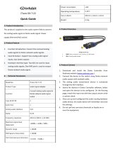
XAvoid positioning the loudspeaker at a distance (dwall) of 0.8 to 1.75m from the wall behind
the loudspeaker. When positioning bass-managed loudspeakers, avoid a distance (dwall) of
0.8 to 1 m from a solid wall behind the loudspeaker. Similarly, avoid these distances from
solid side walls or a solid ceiling. Respecting these positioning limitations reduces the
chances of dips in the low frequency response (comb filtering) caused by strong reflections.
XPrint out the “Installation angles” diagram that can be found at the end of this operating
manual.
XPlace the diagram at the listening position or the center of the listening area.
XUsing a tape measure, place the loudspeakers at the same distance from the center of the
diagram “Installation angles”. To ensure good imaging, do this at an accuracy of at least
1cm.
XIf the loudspeakers cannot be placed at the same distance from the listening position, com-
pensate for distance dierences > 1cm by delaying closer loudspeakers by 30 s/cm. The
MA 1 – Automatic Monitor Alignment software automatically compensates for dierent dis-
tances between the loudspeakers and the listening position.
XArrange the loudspeakers as follows:
2.0 systems (stereo): ± 30°, plus optional subwoofer(s)
5.1 systems:
ITU-R BS.775-1: 0°, ±30°, ±110° (±10°), plus optional subwoofer(s)
(center, front left/right, surround left/right)
ANSI/SMPTE 202M: 0°, ± 22.5°, one surround array left and right, plus optional
subwoofer(s)
7.1 systems: 0°, ± 30°, ± 90°, ± 150°, plus optional subwoofer(s)
(center, front left/right, side left/right, back left/right)
3D systems See the recommendations from Dolby, DTS, Auro3D and
ITU-R BS.2051-0 for loudspeaker positioning.
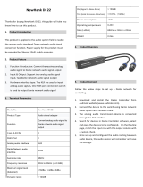
The acoustical axis of the loudspeaker is between the bass and tweeter drivers.
XAlways point the acoustical axis, in the horizontal and vertical planes, towards the listening
position.
The acoustical axis is a line perpendicular to the loudspeaker’s front panel along which
the microphone was placed to tune the loudspeaker’s crossover when the monitor was
designed. Pointing the acoustical axis, in the horizontal and vertical planes, toward
the listening position or center of the monitoring area will give the best measured and
perceived transient response quality.
XPosition the loudspeaker so that there is a direct line of sight from the listening position to
the bass and tweeter drivers.
XMake sure that the ports are not blocked or partially covered.
XKeep sharp edges away from the port outlets, as they can cause air noise.
Distances
d
wall
Angular positioning
of the loudspeakers
KH 120 II:
x = 91 mm
y = 166 mm
KH 150:
x = 112,5 mm
y = 197 mm
EN
KH 120 II AES67 / KH 150 AES67 | 8
Connecting audio signals
XAlways use good quality cables to achieve the maximum cable lengths shown below:
Signal (connec-
tor) Cable length Connection method
Analog (XLR) Up to 100 m Directly to the ANALOG INPUT socket (XLR) (see
below)
Analog (jack) Up to 100 m Via an adapter (jack–XLR) to the ANALOG INPUT
socket (XLR) (see below)
Analog (RCA) Up to 10m Via an adapter (RCA–XLR) to the ANALOG INPUT
socket (XLR) (see below)
Digital (RCA) Up to 200 m Directly to the DIGITAL INPUT socket (RCA) (see
below)
Digital (BNC) Up to 200 m Via an adapter (BNC–RCA) to the DIGITAL INPUT
socket (RCA) (see below)
Digital (XLR) Up to 50 m Via an adapter (XLR–RCA) to the DIGITAL INPUT
socket (RCA) (see below)
AES67 (RJ-45) Depending on
CAT type of
the cable
Via Ethernet connectors (RJ-45)
XIf possible, use a balanced, analog signal connection (XLR, stereo jack) to prevent interfer-
ence in the cable.
Connecting analog signals to the loudspeaker
XConnect the left and right output of your analog audio source to the XLR input sockets of the
respective loudspeaker.




*BASS *LOWMID *HI *INPUT SELECT GROUND LIFT CONTROLdB SPL









ANALOG
AES L
AES R
MONO
, 


*INPUT GAIN
dB
ACOUSTICAL CONTROLS [dB] SETTINGS
*OUTPUT LEVEL
Li
Ground
Local
Network
MAINS POWER
电源
小心
RISK OF ELECTRIC SHOCK
DO NOT OPEN / RISQUE DE CHOC
ÉLECTRIQUE – NE PAS OUVRIR
电击风险
请勿打开
DIGITAL
AESid INPUT
OUTPUT
ON
OFF
ANALOG INPUT
Max. input level  dBu
electronically balanced
   V~  /  Hz
Max. Power Consumption
最大功耗
 W
MANUFACTURER
制造商
GEORG NEUMANN GMBH
Leipziger Str.   Berlin
DESIGNED IN GERMANY
MADE IN CZECH REPUBLIC
德国设计 捷克共和国制
Max. input level
. V pk-pk
unbalanced
KH  II
TWO-WAY ACTIVE LOUDSPEAKER
HIGH RESOLUTION
NETWORK CONTROLLABLE
ETHERNET
CONTROL NETWORK
XLR XLR
left signal
right signal
Analog source
XUse an XLR adapter (not supplied) to connect unbalanced cables (e.g. RCA cables).
XUse this adapter directly at the source and connect the adapter via a properly wired bal-
anced XLR cable to the loudspeaker. The connection of pin 3 to ground should be as close as
possible to the source to maximize hum rejection on the cable.
Connecting XLR
or RCA cables
EN
KH 120 II AES67 / KH 150 AES67 | 9
XUse the following wiring if you want to make your own RCA-to-XLR cable:
loudspeaker
XLR-
M
1
3
2
short adapter
long symmetrical
XLR cable
XLR-M
1
3
2
2
3
1
XLR-F
CD
stereo source
RCA
2
3
1
XLR-F
loudspeaker
XLR-
M
1
3
2
long adapter cable
CD
stereo source
RCA
2
3
1
XLR-F
Connecting digital AES3id and S/PDIF signals to the loudspeaker
XConnect the digital AES3id or S/PDIF output signal of your audio source to the DIGITAL S/
PDIF INPUT socket on the first loudspeaker (see figure below).
The loudspeaker only supports non-encoded AES3 and S/PDIF signals. Encoded signals
such as MP3, DTS or Dolby Digital are not supported. The cable connection must be
unbalanced with a characteristic impedance of 75 .
Only one cable is needed for uncompressed AES3 and S/PDIF digital signals (single-wire
mode). They contain two audio channels: “subframe A” and “subframe B.” Usually, the
audio channels are:
Subframe A Subframe B
Left Right
Center LFE
Surround left Surround right
Back left Back right
A clock input is not required because loudspeakers are not audio sources and the con-
verters are clocked to a very stable internally generated clock source.
If the signal source is based on internal digital signal processing, it is recommended
that you choose a digital connection between the signal source and the loudspeaker.
This eliminates the need for additional signal conversion from digital to analog in the
source and from analog to digital in the loudspeaker. This also applies if you are con-
necting to an upstream DSP subwoofer (e.g. KH 750 DSP). This should be connected to
the loudspeakers via its digital output.
Note that the supplied digital signal often has a maximum signal level, and that the
level in the source is often not adjustable. Therefore, before making the digital connec-
tion, set the OUTPUT LEVEL switch on the loudspeaker to 94dB SPL and the INPUT GAIN
knob to -15dB.
XConnect the DIGITAL S/PDIF OUTPUT socket on the first loudspeaker to the DIGITAL S/PDIF
INPUT socket on the second loudspeaker.
XSet the INPUT SELECT switch on the left loudspeaker to S/PDIF L and the INPUT SELECT
switch on the right loudspeaker to S/PDIF R. The CONTROL switch must be in the Local
position.
Connecting
AES3 cables
EN
KH 120 II AES67 / KH 150 AES67 | 10




*BASS *LOWMID *HI *INPUT SELECT GROUND LIFT CONTROLdB SPL









ANALOG
S/PDIF L
S/PDIF R
AES
, 


*INPUT GAIN
dB
ACOUSTICAL CONTROLS [dB] SETTINGS
*OUTPUT LEVEL
Li
Ground
Local
Network
SECONDARY
ETHERNET
AES67 AUDIO AND
CONTROL NETWORK
MAINS POWER 电源
小心
RISK OF ELECTRIC SHOCK
DO NOT OPEN / RISQUE DE CHOC
ÉLECTRIQUE – NE PAS OUVRIR
电击风险
请勿打开
DIGITAL
S/PDIF INPUT
OUTPUT
ON
OFF
ANALOG INPUT
Max. input level  dBu
electronically balanced
   V~  /  Hz
Max. Power Consumption
最大功耗
 W
MANUFACTURER
制造商
GEORG NEUMANN GMBH
Leipziger Str.   Berlin
DESIGNED IN GERMANY
MADE IN CZECH REPUBLIC
德国设计 捷克共和国制
Max. input level
. V pk-pk
unbalanced
HIGH RESOLUTION
NETWORK AUDIO
TWO-WAY ACTIVE LOUDSPEAKER
Digital source
S/PDIF
right loudspeaker:
INPUT SELECT switch: S/PDIF R
left loudspeaker:
INPUT SELECT switch: S/PDIF L
The settings of the first loudspeaker in the signal chain are not looped through to the
second loudspeaker. Each loudspeaker must be configured separately.
When using a daisy chain connection as shown here, the signal from the second loud-
speaker is not delayed relative to the first loudspeaker.
The output of the final loudspeaker does not have need to be terminated with an addi-
tional 75ohms. It is terminated internally.
Connecting digital AES67 signals to the loudspeaker
In order to use the AES67 digital audio network stream, please observe the chapter “Configur-
ing AES67 network and audio settings” on page 20, which provides detailed information on
the entire AES67 configuration and usage.
Connecting a network cable for network control
To use the extended functionality oered by the MA 1 – Automatic Monitor Alignment soft-
ware, the loudspeaker must be connected via the PRIMARY socket to a standard network
switch using a user supplied standard Ethernet cable (Cat 5 or better). The maximum length of
the cable is 100 m.
Refer to the MA 1 – Automatic Monitor Alignment software for information about how to use
loudspeakers in a network.
ANALOG
S/PDIF L
S/PDIF R
AES67
DIGITAL
S/PDIF
ANALOG
S/PDIF L
S/PDIF R
AES67
DIGITAL
S/PDIF
ANALOG
S/PDIF L
S/PDIF R
AES67
DIGITAL
S/PDIF
ANALOG
S/PDIF L
S/PDIF R
AES67
DIGITAL
S/PDIF
RJ45 RJ45 RJ45RJ45
Network Switch
This device supports Sennheiser Sound Control (SSC) based on TCP and IPv6. The static
IPv6 address of the device can be determined with mDNS. For more information about
SSC, see the Sennheiser website.
Connecting
AES67 audio
network cables
EN
KH 120 II AES67 / KH 150 AES67 | 11
Connecting/disconnecting the loudspeaker to/from the
power supply system
To connect the loudspeaker to the power supply system:
XMake sure that the on/o switch is set to “O”.
XConnect the IEC connector on the supplied power cable to the power supply socket.
Power Source
XConnect the wall plug on the power cable to a suitable wall outlet.
To completely disconnect the loudspeaker from the power supply system:
XSet the on/o switch to “O”.
XPull the wall plug out of the wall outlet.
Configuring and using the loudspeaker
Switching the loudspeaker on/o




*BASS *LOWMID *HI *INPUT SELECT GROUND LIFT CONTROLdB SPL









ANALOG
S/PDIF L
S/PDIF R
AES
, 


*INPUT GAIN
dB
ACOUSTICAL CONTROLS [dB] SETTINGS
*OUTPUT LEVEL
Li
Ground
Local
Network
MAINS POWER
电源
小心
RISK OF ELECTRIC SHOCK
DO NOT OPEN / RISQUE DE CHOC
ÉLECTRIQUE – NE PAS OUVRIR
电击风险
请勿打开
DIGITAL
S/PDIF INPUT
OUTPUT
ON
OFF
ANALOG INPUT
Max. input level  dBu
electronically balanced
   V~  /  Hz
Max. Power Consumption
最大功耗
 W
MANUFACTURER
制造商
GEORG NEUMANN GMBH
Leipziger Str.   Berlin
DESIGNED IN GERMANY
MADE IN CZECH REPUBLIC
德国设计 捷克共和国制
Max. input level
. V pk-pk
unbalanced
KH  II
TWO-WAY ACTIVE LOUDSPEAKER
HIGH RESOLUTION
NETWORK CONTROLLABLE
ETHERNET
CONTROL NETWORK
On/Off
XSet the on/o switch to:
“I” to switch on the loudspeaker. The Neumann logo lights up solid red while the DSP
system boots up. The loudspeaker is ready for operation as soon as the light turns white
(after approx. 5seconds if the INPUT SELECT switch is in the ANALOG or S/PDIF position,
after approx. 2.5 minutes if the INPUT SELECT switch is in the AES67 position). Using the
software MA 1 – Automatic Monitor Alignment allows you to to dim the logo or switch it
o ccompletely after the boot phase is complete.
“OFF” to switch o the loudspeaker. The Neumann logo switches to red for a short moment
and then goes o.
Once it switches on, the loudspeaker remains muted (5seconds if the INPUT SELECT
switch is in the ANALOG or S/PDIF position, 2.5 minutes if the INPUT SELECT switch
is in the AES67 position). This suppresses any noise that would be generated by con-
nected devices that are switched on at the same time. Conversely, switching o the
loudspeaker immediately mutes the audio.
EN
KH 120 II AES67 / KH 150 AES67 | 12
Functionality of the Neumann logo
Action Logo indication
Firmware activities
Loudspeaker is booting up, muted Solid red:
5 seconds for switch setting
INPUT SELECT = ANALOG or S/
PDIF
2.5 minutes for switch setting
INPUT SELECT = AES67
Loudspeaker is shutting down, muted Brief red light
Loudspeaker boot up error Red flashing (fast)
Loudspeaker firmware is being updated Solid pink
Loudspeaker resetting to factory default settings Pink flashing (very fast)
Normal operation
Loudspeaker switched on and ready for operation
(can be dimmed using MA 1 – Automatic Monitor
Alignment software)
Solid white
MA 1 – Automatic Monitor Alignment software is
saving the changes to the loudspeaker
Solid white
Protection and standby
Peak limiter active Brief red light in time with the
pulse peaks
Thermolimiter active Solid red as long as level
reduction is active
Overload protection Solid red as long as the
loudspeaker is muted to prevent
overheating
Other protection system is activated (takes priority
over other indications)
Red
Calibration with the MA 1 – Automatic Monitor Align-
ment software
Identifying the loudspeaker Flashing pink (2Hz)
Loudspeaker is selected Solid white
EN
KH 120 II AES67 / KH 150 AES67 | 13
Switches on the SETTINGS panel
The three switches on the SETTINGS panel control dierent functions.
CONTROL
The CONROL switch toggles between backplate mode and network mode.
Local – backplate mode
If the CONTROL switch is in the Local position, the loudspeaker will not respond to network
commands. The loudspeaker can only be controlled using the controls on the backplate.
Network – network mode
If the CONTROL switch is in the Network position, the loudspeaker responds to the network
commands from the MA 1 – Automatic Monitor Alignment software. The controls marked * on
the back of the loudspeaker are ignored.
If the CONTROL switch is set to Network but there is no network connection and the MA 1 –
Automatic Monitor Alignment software is not active, the most recent network configuration is
used.
If you have configured any settings via the MA 1 – Automatic Monitor Alignment software and
you remove the network cable, the current settings will stay active.
By switching from network control to local control, you can easily switch between a configu-
ration set in the MA 1 – Automatic Monitor Alignment software and settings made directly on
the loudspeaker.
This is useful if you want to temporarily use the loudspeaker in a location other than the studio
environment you configured.
The loudspeaker does not lose its settings even when you disconnect it from the network or
the power supply.
INPUT SELECT
The INPUT SELECT switch toggles between the analog input and the digital inputs.
Set the INPUT SELECT switch to ANALOG if you intend to feed an analog signal into the XLR
socket labeled ANALOG INPUT.
Set the INPUT SELECT switch to S/PDIF L or S/PDIF R if you intend to feed a digital AES3id or
S/PDIF signal into the RCA socket labeled DIGITAL S/PDIF INPUT.
Set the INPUT SELECT switch on the left loudspeaker to S/PDIF L and the right speakers INPUT
SELECT switch to S/PDIF R for normal stereo mode.
If the loudspeakers are used as surround speakers in larger systems, the channels must be
configured based on how they are assigned in the source. In this case, channel A (digital sub-
frame A) corresponds to the left channel and channel B (digital subframe B) corresponds to the
right channel.
Set the INPUT SELECT switch to AES67 if you want to feed in a digital AES67 signal via the
Ethernet interface. Only the first channel of the AES67 audio stream is played.
Switch position Meaning
ANALOG XLR socket ANALOG INPUT is active
S/PDIF L Digital subframe A, RCA socket DIGITAL S/PDIF INPUT is active
S/PDIF R Digital subframe B, RCA socket DIGITAL S/PDIF INPUT is active
AES67 AES67 audio network stream, RJ-45 sockets PRIMARY and
SECONDARY are active
*INPUT SELECT GROUND LIFT CONTROL
0
ANALOG
S/PDIF L
S/PDIF R
AES67
-3
*INPUT GAIN
[dB]
SETTINGS
Li
Ground
Local
Network
*INPUT SELECT GROUND LIFT CONTROL
0
ANALOG
S/PDIF L
S/PDIF R
AES67
-3
*INPUT GAIN
[dB]
SETTINGS
Li
Ground
Local
Network
*INPUT SELECT GROUND LIFT CONTROL
0
ANALOG
S/PDIF L
S/PDIF R
AES67
-3
*INPUT GAIN
[dB]
SETTINGS
Li
Ground
Local
Network
EN
KH 120 II AES67 / KH 150 AES67 | 14
GROUND LIFT
The GROUND LIFT switch internally separates pin 1 of the XLR input socket from the electron-
ics chassis ground.
If there is humming or buzzing noise coming from the loudspeaker, first search for the cause
of the noise:
XDisconnect all input cables from the loudspeaker.
If the noise goes away, it is probably coming from the audio source or source cabling. It might
be possible to eliminate the noise by disconnecting the ground from the input signals (activat-
ing ground lift).
To activate the ground lift:
XReconnect the signal cables and set the GROUND LIFT switch to Lift.
For safety reasons, the electronics chassis ground is always connected to the ground
contact of the power supply. Never disconnect the ground contact of the power cable
from ground.
Resetting the loudspeaker settings
You can use the MA 1 – Automatic Monitor Alignment software to configure the loudspeaker
beyond what is available on the backplate.
To reset these internal loudspeaker parameters to the factory settings:
XSet the INPUT SELECT switch to ANALOG, S/PDIF L or S/PDIF R.
XSwitch on the loudspeaker.
XWhile the logo is flashing during the boot up phase, move the CONTROL switch up and down
repeatedly. Continue until the logo turns solid white for a few seconds.
The logo begins quickly flashing red for a few seconds before turning white again.
Firmware update
Firmware updates are done via the MA 1 – Automatic Monitor Alignment software. When you
open the software, it scans the network for loudspeakers and checks if the firmware is up to
date. If a firmware update is required, you will be notified. Follow the instructions shown on
screen.
It takes approximately 10 seconds per loudspeaker to update the loudspeaker firmware.
The AES67 firmware update may take up to 30 minutes.
*INPUT SELECT GROUND LIFT CONTROL
0
ANALOG
S/PDIF L
S/PDIF R
AES67
-3
*INPUT GAIN
[dB]
SETTINGS
Li
Ground
Local
Network
EN
KH 120 II AES67 / KH 150 AES67 | 15
Adapting loudspeakers to the environment using the
switches on the backplate
When the switches BASS, LOW-MID and HI on the ACOUSTICAL CONTROLS panel are set to 0,
the loudspeaker is designed to have a flat frequency response in anechoic conditions.
The frequency response will change in your monitoring environment. The loudspeaker’s fre-
quency response will also change based on its position in the room. The same loudspeaker
installed in dierent positions in the same room may require dierent acoustical control set-
tings. In a symmetrical installation, left/right pairs (front or back) will probably have the same
acoustical settings.
XBefore using your loudspeaker system for the first time, align the frequency response of the
loudspeakers in the room in order to obtain the desired transfer behavior.
XRepeat the above step if you change the physical conditions in your studio.
XAt your listening position, determine the frequency response of each loudspeaker.
These switches are not intended for adjusting the sound to your preferences during
playback. They are used to adapt the loudspeaker to the acoustical conditions of the
room and the position in the room to provide as neutral a response as possible.
Switch Function Possible settings
BASS Compensates for acoustical loading in the
low frequency range due to nearby large
solid boundaries (e.g. walls).
0, -2, -4, -6 dB
LOW-MID Compensates for acoustical loading in the
low-mid frequency range due to large,
reflecting objects (e.g. mixing consoles,
tables or screens) in the vicinity of the
loudspeaker.
0, -2, -4, -6 dB
HI Compensates for insucient or excessive
high-frequency damping in the room.
+1, 0, -1, -2 dB
The following settings can be used as a starting point for further adjustment:
Loudspeaker position Switch
BASS LOW-MID HI
In a corner -6 dB -2 dB
Next to an acoustically solid wall
(e.g. brick, concrete)
-4 dB
Next to an acoustically soft wall (e.g.
drywall)
-2 dB
Free standing in an untreated room -2 dB -1 dB
Free standing in a well-treated room
In a small room with strong side wall
reflections
-4 dB 0 dB
Near a small desktop or small reflecting
surface*
-2 dB
Near a large desktop or large reflecting
surface*
-4 dB
*Use these settings in addition to one of the top settings.
114
108
100
94
*BASS *LOW-MID *HI
0
-2
-4
-6
0
-2
-4
-6
1
0
-1
-2
ACOUSTICAL CONTROLS [dB]
*OUTPUT LEVEL
EN
KH 120 II AES67 / KH 150 AES67 | 16
Adjusting the acoustical level
XOn your loudspeakers, set the OUTPUT LEVEL switch to 94dB SPL and the INPUT GAIN knob
to 15dB.
XPlay a broadband pink noise test signal that is set to 18dBFS (Europe) or 20dBFS (USA)
on the mixing console’s output level meters.
XMeasure the sound pressure level at the listening position. Use a sound level meter with the
following settings:
“C” weighted
Slow integration time
XSet the OUTPUT LEVEL switch and INPUT GAIN control of your loudspeakers so that the
desired acoustic level is obtained.
Recommended sound pressure levels:
Application Sound pressure level
Film 85 dB(C)
Broadcast 79 to 83 dB(C)
Music No defined reference levels
If the Neumann logo flashes red, the loudspeaker’s protection system has been activated. To
avoid this and achieve the desired output level, use larger loudspeakers or add a bass man-
aged subwoofer to the system.
Examples of sound pressure levels as a function of the loudspeaker’s input and output level:
Input signal
dBu
0
(0.775 V)
0
(0.775 V)
+4
(1.23 V)
-20
(77.5 mV)
INPUT GAIN knob
dB 0 -15 -4 -15
OUTPUT LEVEL switch
dB SPL 100 100 94 114
Sound pressure level
dB SPL in 1 m
100 85 94 79
If your signal source is not used as a reference for the listening level, make sure that the
level of the source is higher and the level on the loudspeakers is lower. This reduces the
self-noise from the source and any extraneous signals in the input line.
114
108
100
94
[dB SPL]
0
-5
ANALOG
AES3 L
AES3 R
MONO
-7,5 -3
-11
-15
*INPUT GAIN
[dB]
*OUTPUT LEVEL
EN
KH 120 II AES67 / KH 150 AES67 | 17
Configuring standby mode
The loudspeaker has an automatic standby function that is dependent on the input signal. It
switches the loudspeaker into power saving mode when it hasn’t been used for a period of
time. The standby function is only enabled when the INPUT SELECT switch is in the ANALOG,
S/PDIF L or S/PDIF R position. When the switch is in the AES67 position, the standby function
is disabled.
Standby means that the network interface, signal processing circuitry and power amplifiers
are all powered down. Standby mode is automatically deactivated when a suciently large
audio signal is detected at the input. The time taken to resume normal operation and hear
sound is 5seconds.
When the INPUT SELECT switch is in the ANALOG position, the loudspeaker switches to standby
mode after 90 minutes without an input signal or with only a very low input level.
For the standby function to be activated, the incoming signal must not cause the loudspeak-
er’s output level to exceed an internally specified threshold for the specified standby time.
This therefore depends on both the amplitude of the input signal and the level setting on the
loudspeaker itself. The level threshold is 20dB SPL at a distance of 1m in free field conditions.
Even if there is no input signal, however, interference and crosstalk in the signal source or
input line can cause the loudspeaker to wake up or prevent the loudspeaker from switching to
standby mode in the first place.
If the INPUT SELECT switch is in the positions S/PDIFL or S/PDIFR, the loudspeaker switches
to standby mode after 90 minutes when there is no digital clock signal or the digital input
signal is muted. In these modes, the loudspeaker wakes up when the digital signal reappears.
Standby mode will remain active as long as the sampling rate of the applied S/PDIF signal
does not change.
When switching to standby mode, a slight pop may be heard.
Standby in backplate mode
XSet the CONTROL switch to Local.
The idle time for standby mode is 90 minutes.
The output level depends on the positions of the OUTPUT LEVEL switch and the INPUT GAIN
knob on the back of the loudspeaker. Set them as required for your setup.
Standby in network mode
XSet the CONTROL switch to Network.
You can disable automatic standby mode using the MA 1 – Automatic Monitor Alignment soft-
ware.
*INPUT SELECT GROUND LIFT CONTROL
0
ANALOG
S/PDIF L
S/PDIF R
AES67
-3
*INPUT GAIN
[dB]
SETTINGS
Li
Ground
Local
Network
*INPUT SELECT GROUND LIFT CONTROL
0
ANALOG
S/PDIF L
S/PDIF R
AES67
-3
*INPUT GAIN
[dB]
SETTINGS
Li
Ground
Local
Network
EN
KH 120 II AES67 / KH 150 AES67 | 18
Customizing standby behavior
Standby is too sensitive
If standby is too sensitive, the loudspeaker will not enter standby mode when it is supposed
to, or it will wake up from standby mode when it is not supposed to.
Possible reasons:
The source may contain extraneous noise or noise peaks that wake the loudspeaker up or
prevent it from going into standby. This can also cause loudspeakers with the same settings to
behave dierently.
You can determine if extraneous noise or noise peaks are responsible for the behavior as fol-
lows:
XSet the CONTROL switch to Local.
XSet the OUTPUT LEVEL switch to 114dB to listen for possible extraneous noise.
XListen carefully to identify noise peaks.
XAlternatively, you can record the loudspeaker output signal with a microphone and analyze
the recording.
XTry to find out whether switching other devices in the house on or o has an eect (e.g.
refrigerator or similar).
You can check that the standby feature is working correctly by connecting a short XLR cable to
the loudspeaker input without connecting a device to the other end of the cable.
Backplate mode:
XIn backplate mode, set the OUTPUT LEVEL switch to 100dB.
The loudspeaker should enter standby mode after 90minutes.
Network mode:
XIn network mode, use the MA 1 – Automatic Monitor Alignment software to set the standby
threshold to 30dB and the standby time to any value.
The speaker should enter standby mode after the time you set.
Since the loudspeaker continuously monitors the input signal, peaks that come from the
source or are induced in the cable can also prevent the loudspeaker from switching to
standby mode. Make sure that there are no peaks coming from the source or induced in
the cable that can wake up the loudspeaker.
EN
KH 120 II AES67 / KH 150 AES67 | 19
Standby is not sensitive enough
If standby is not sensitive enough, the loudspeaker goes into standby mode when it is not
supposed to, or does not wake up from standby mode when it is supposed to.
Possible reasons:
The standby threshold is above the signal level. If the input and output levels of the loud-
speaker are set very low, but the source has a high level, this can result in a very quiet output
signal.
Backplate mode:
XIn backplate mode, raise the source output level or the input and output levels of the loud-
speaker in order to raise the sound pressure level above the standby threshold.
Network mode:
XIn network mode, raise the source output level or the input and output levels of the loud-
speaker in order to raise the sound pressure level above the standby threshold.
In general, you should set the loudspeaker level as low as possible (e.g., the INPUT GAIN knob
to 0, the OUTPUT LEVEL switch to 94 or 100dB SPL) and the level of your source as high as
possible to obtain the best possible signal-to-noise ratio and minimize induced extraneous
noise.
Ideally, the source should be connected to the loudspeaker using a balanced XLR cable (XLR to
XLR or jack to XLR). If only an unbalanced source is available, you should connect it as shown
in the following figures.
Headphone output (TV or hi-fi system): miniature jack (3.5mm) or jack (6.3mm):
Tip
Ring
Sleeve
Source (TRS Jack)
Stereo unbalanced TRS Jack to balanced XLR connections
Left loudspeaker (XLR-M)
Right loudspeaker (XLR-M)
RCA line output from a television (if the output level is adjustable) or RCA output (pre-amp)
from an AV receiver. One cable is required per speaker:
Source (RCA)
Unbalanced RCA to balanced XLR connections
Loudspeaker (XLR-M)
EN
KH 120 II AES67 / KH 150 AES67 | 20
Configuring AES67 network and audio settings
Initial setup
Before using the loudspeaker in your network, we recommend checking the AES67 network
settings and following this procedure for the initial setup of the AES67 interface.
The initial loudspeaker configuration and setup is divided into the following two procedures:
The operational audio control mode: see the chapter “Selecting the control mode and audio
input”.
AES67-compatible network interface: see the chapter “Setting up the AES67 network inter-
face” on page 21.
XFollow the steps described in these chapters in order to configure your AES67 network.
Selecting the control mode and audio input
The loudspeaker oers two dierent control modes to perform the audio configuration.
In backplate mode (CONTROL = Local), all settings are performed via the controls on the
loudspeaker’s backplate.
In network mode (CONTROL = Network), the controls on the backplate marked with “*” are
disabled. Settings can only be made using the MA 1 – Automatic Monitor Alignment soft-
ware.
For more information on the two loudspeaker control modes, refer to the chapter “CON-
TROL” on page 13.
Setting the control mode for initial setup
XSet the CONTROL switch to Local.
XKeep it in this position during the initial AES67 setup.
Once the initial setup is done:
XSet the CONTROL switch to Network in order to use the MA 1 – Automatic Monitor Alignment
software for your individual room calibration.
For more information on the MA 1 – Automatic Monitor Alignment software, refer to:
https://en-de.neumann.com/ma-1
Setting the audio input mode for initial setup
XSet the INPUT SELECT switch to AES67 in order to activate the AES67 audio and network
ports.
For more information on selecting the audio input signals, refer to the chapter “INPUT
SELECT” on page 13.
*INPUT SELECT GROUND LIFT CONTROL
0
ANALOG
S/PDIF L
S/PDIF R
AES67
-3
*INPUT GAIN
[dB]
SETTINGS
Li
Ground
Local
Network
*INPUT SELECT GROUND LIFT CONTROL
0
ANALOG
S/PDIF L
S/PDIF R
AES67
-3
*INPUT GAIN
[dB]
SETTINGS
Li
Ground
Local
Network
*INPUT SELECT GROUND LIFT CONTROL
0
ANALOG
S/PDIF L
S/PDIF R
AES67
-3
*INPUT GAIN
[dB]
SETTINGS
Li
Ground
Local
Network
EN
  • Page 1 1
  • Page 2 2
  • Page 3 3
  • Page 4 4
  • Page 5 5
  • Page 6 6
  • Page 7 7
  • Page 8 8
  • Page 9 9
  • Page 10 10
  • Page 11 11
  • Page 12 12
  • Page 13 13
  • Page 14 14
  • Page 15 15
  • Page 16 16
  • Page 17 17
  • Page 18 18
  • Page 19 19
  • Page 20 20
  • Page 21 21
  • Page 22 22
  • Page 23 23
  • Page 24 24
  • Page 25 25
  • Page 26 26
  • Page 27 27
  • Page 28 28
  • Page 29 29
  • Page 30 30
  • Page 31 31
  • Page 32 32
  • Page 33 33
  • Page 34 34
  • Page 35 35
  • Page 36 36
  • Page 37 37
  • Page 38 38
  • Page 39 39

Neumann KH 120 II AES67 User manual

Type
User manual

Ask a question and I''ll find the answer in the document

Finding information in a document is now easier with AI