Page is loading ...

Pressure seal filters
Installation and Maintenance Instructions
Emerson reserves the right to change the contents without notice RAILT-0048-EN-1310
Introduction
This manual provides guidelines to be observed for the following operations:
• storage
• installation into the pipeline
• maintenance
• preservation
The manual is intended for the following personnel/staff:
• plant warehouse staff,
• installers,
• maintenance engineers.
1. Filter storage and preservation before installation: verification and inspection
On arrival of materials, it is recommended to:
• check the integrity of the case/packing
• open the case and verify that there is no damage due to transportation
• do not open the barrier bag (if existing)
• verify that the contents are those indicated on the packing list
• store the filters (unless damaged) in their original packaging.
Please observe the following:
1. do not place packages directly on the ground
2. do not expose packages to direct sunlight or adverse weather conditions
3. check the packages every two months
4. substitute the silica gel every six months. This is not applicable in the case of barrier bag
packages.
2. Handling
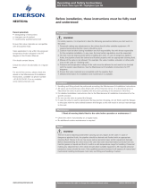
During handling operations, the filters must be lifted and handled as indicated in fig. 1 by using
lifting equipment (fasteners, hooks, etc.) which must be sized and selected on the basis of the filter
weight (indicated in the drawings).
Use the filters’ lifting lugs and eyebolts for all handling and lifting operations.
Warning
This symbol means “Warning” and indicates all matters relating to safety. Please read the
warning notices carefully and follow the instructions. These serve to guarantee your safety
and to prevent damage to people and property.
Warning
Do not use any lifting straps that are either damaged or of inadequate/unknown size.
In addition to the instructions in this manual, specific plant safety regulations must always be
followed.
It is strongly recommended that this manual is read carefully and entirely, before starting
any maintenance activity, in order to optimise the intervention timing, and to ensure that
suggested spare parts and gaskets are available in the event of valve assembly.
For installation and maintenance operations no specific equipment or tools are required, other than
those usually available in the plant.
Emerson is always at the Customer’s disposal for any further technical information.
Fig. 1 - Filter lifting and handling
RAIMONDI
www.valves.emerson.com

Pressure seal filters
Installation and Maintenance Instructions
Emerson reserves the right to change the contents without notice page 2
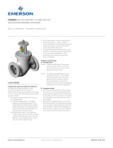
3. Installation
For correct operation, filters must be installed and oriented as indicated in fig. 2. A different
installation may result in a faulty performance and/or rapid product deterioration.
The following operations must be performed only immediately before the installation:
1. Remove the protection caps from the end faces.
2. Check the upstream and downstream pipeline sections. Make sure that there are no solid
particles or any other kind of dirt or debris inside. If necessary, clean carefully by using an air
line.
3. Pay attention to the flow direction.
Warning
Before starting filter installation, please
verify that:
the valve class is suitable for the required
operating pressure, and the materials of
construction are suitable for the intended
service (type of process fluid).
Warning
Protect eyes with appropriate welding
masks or goggles during all welding
operations.
Warning
In order to avoid any damage, the
differential pressure must never exceed
1.5 bar.
Warning
Verify that the flow direction of the line corresponds to the flow direction indicated by the
arrow on the filter body.
Flanged version
Position the filter between the two flanges of the pipe and put the seal gasket between the filter
flange and the pipe flange. Ensure that it is correctly positioned. Mount the filter to the pipe with
bolts, which must be cross-tightened. Progressively reach the requested torque indicated by the
engineering company that designed the plant.
Butt-weld version
Position the filter and verify its alignment with the pipe. Proceed with the welding operation in
accordance with the procedure indicated by the engineering company that designed the plant.
In general, the first weld layer will be made with TIG, while the following layers will be made with
an appropriate electrode for the filter body material.
General notes
In case that one end of the wire is not connected to the line for a period of time longer than half a
day, the open end must be properly closed and sealed in order to prevent entry of dirt or debris.
Check that there is enough space to easily remove the cover and the filter.
Upstream and downstream gauges must be present on the line in order to verify the proper
performance of the filter.
4. Scheduled maintenance
4.1 Routine inspection
• The filter must be periodically cleaned, depending on the service and type of fluid – at least once
a month – by means of the blow-down valve, installed on the cover.
• Verify that the differential pressure between filter upstream and downstream is not above
0.4-0.8 bar.
4.2 Preventive operations
• Clean the filter at least once a year.
5. Troubleshooting guide
Below is a list with of most common problems. However, the list does not include every possible
problem that may occur.
5.1 Body-bonnet joint leakage
Leakage from the body-bonnet joint during plant operation requires immediate action, since it may
cause irreparable damage to the filters in the line.
Possible causes of leakage are:
• a previous, incorrect filter reassembly
• the reutilisation of the pressure seal gasket.
5.2 The differential pressure tends to increase
• The filter is clogged. Clean the filter.
Fig. 2 - Possible installation positions
Flow
Flow

Emerson reserves the right to change the contents without notice page 3
Pressure seal filters
Installation and Maintenance Instructions
6. Disassembly Instructions
Below are the procedures to disassemble filters. Before starting any operation, it is important to:
• identify the problem;
• clean the area around the filter that is to be disassembled;
• arrange for a box or pallet for all components;
• arrange for a polyethylene sheet to protect all components and to prevent particles from
inadvertently entering the body.
1. Loosen the nuts (9).
2. Remove the safety ring (4).
3. Remove the segment rings (5) by pushing them outside through the four radial holes in the body.
4. Reassemble the safety ring and nuts (9).
5. Tighten the nuts (9) of the bonnet bolts (8), until the bonnet is lifted. Remove the ring (6) and the
pressure seal gasket (7).
6. Remove the safety ring and nuts (4).
7. Once the gasket has been removed, proceed to remove the bonnet (2) and the filter (67).
8. Clean the filter or substitute it.
Start immediately with the filter cleaning procedure, using pressurized water or steam.
7. Assembly Instructions
Before starting assembly it is recommended to verify the following points:
• Remove any dirt or particles with a wire brush or abrasive cloth; remove any oil or grease with a
suitable solvent, to avoid damage cause by foreign particles – in particular to the sealing area.
• Never re-use the old gaskets, even though they seem to be in good condition.
• Verify that there are no scratches on the body sealing area.
7.1 Type “I”
1. Place a new pressure seal gasket on the bonnet. Install on the body the assembly body/filter.
2. Place the ring 6) and the segment rings (5).
3. Insert the safety ring (4) and tighten the nuts (9) to tightening torque values indicated in table I.
4. Once the filter has been pressurized, verify that the nuts (9) are tightened to the torque values
indicated in table I.
8. Spare parts list
Emerson guarantees the supply of any spare part for a period of at least ten years from the
manufacturing date (month/year) indicated on the tag plate.
This table indicates the suggested spare parts and related quantities.
Item Description Percentage (1) Minimum quantity
7 Gasket 20% 2
67 Filter 10% 1
(1) Percentages must be calculated with reference to equivalent filters and must be rounded up to
a whole number.
Warning
Before starting filter disassembly it
isveryimportant to verify – for your
safety – that:
• the line is not pressurized;
• the line is at ambient temperature.

9
8
4
5
6
7
2
11
67
1
1/2” 5 (50) 1/2” 2 (20)
5/8” 10 (100) 5/8” 3 (30)
3/4” 17 (170) 3/4” 5 (49)
7/8” 29 (280) 7/8” 9 (88)
1” 43 (420) 1” 13 (130)
1 - 1/8” 61 ( 600) 1 - 1/8” 18 (180)
1 - 1/4” 86 (850) 1 - 1/4” 26 (255)
1 - 3/8” 112 (1100) 1 - 3/8” 34 (335)
200 220 190.7 - 240 0005 A1 LBA30 AT080 1
Pressure seal filters
Installation and Maintenance Instructions
Emerson reserves the right to change the contents without notice page 4
9. Appendices
The reference drawings are those relating to the supply only. The drawings published in this
manual are typical drawings only and may not represent the filters supplied.
Fig. 3 - Typical filter
Table 1 - Tightening torque values for bolts/screws
Bolts/Screws: A 193 B7 Bolts/Screws: A 193 B8
Ø Bolts/Screws Torque values Ø Bolts/Screws Torque values
Kgm (Nm) Kgm (Nm)
Table 4 - Partslist
Pos. Part name Material
1 Body 16Mo3
2 Bonnet 10CrMo9-10
4 Safety ring A 105
5 Segment ring 10CrMo9-10
6 Ring 10CrMo9-10
7 Gasket Pure graphite
8 Bolts A 193 B8
9 Nuts A 194 8
11 Screws A 182 F304
67 Filter AISI 304
Table 2 - Dimensions in mm
DN øA øB B.W.E Weight (kg) Item T.A.G. Pieces
Table 3
Design conditions Test conditions
Pressure 79 bar Hydr. Tightness
Temperature 480°C 198 bar Water Air
87bar 6 bar
B.W. detail
/