Page is loading ...

waterpurification.pentair.com
FLECK 2510
SERVICE MANUAL

2 • FLECK 2510 Service Manual
TABLE OF CONTENTS
JOB SPECIFICATION SHEET ...............................................2
INSTALLATION .....................................................................3
START-UP INSTRUCTIONS..................................................3
3200 TIMER SETTING PROCEDURE .................................... 4
3210 TIMER SETTING PROCEDURE .................................... 4
3200, 3210, 3220, 3230 REGENERATION CYCLE
SETTING PROCEDURE .......................................................5
3200 TIME CLOCK TIMER ASSEMBLY .................................6
3210 METER DELAYED TIMER ASSEMBLY ......................... 8
3220 METER IMMEDIATE TIMER ASSEMBLY ...................10
2510 SXT VALVE ................................................................. 12
2510 MANUAL VALVE ........................................................12
2510 ELECTROMECHANICAL SOFTENER METER ............12
2510 ELECTROMECHANICAL SOFTENER TIME CLOCK ...12
2510 ELECTROMECHANICAL FILTER TIME CLOCK ......... 12
2510 VALVE ACCESSORIES ...............................................13
2510 VALVE CONVERSION ASSEMBLIES ..........................14
POWERHEAD ASSEMBLY (ENVIRONMENTAL) ................. 16
MANUAL POWERHEAD ASSEMBLY ..................................18
CONTROL VALVE ASSEMBLY ............................................ 19
METER ASSEMBLY ............................................................21
1600 BRINE SYSTEM ASSEMBLY ...................................... 22
1650 BRINE SYSTEM .........................................................23
BYPASS VALVE ASSEMBLY (PLASTIC) ..............................24
BYPASS VALVE ASSEMBLY (METAL) ................................25
2300 SAFETY BRINE VALVE ..............................................26
2310 SAFETY BRINE VALVE ..............................................27
SEAL & SPACER TOOLS & REPLACEMENT .....................29
GENERAL SERVICE HINTS FOR METER CONTROL ..........30
TROUBLESHOOTING ..........................................................31
FLOW DATA & INJECTOR DRAW RATES ..........................32
WIRING ...............................................................................33
SERVICE ASSEMBLIES ......................................................34
JOB SPECIFICATION SHEET
Job Number: ______________________________________________
Model Number: ____________________________________________
Water Hardness: __________________________________ ppm or gpg
Capacity Per Unit: __________________________________________
Mineral Tank Size: ___________ Diameter: ________Height: ________
Salt Setting per Regeneration: ________________________________
1. Type of Timer:
A. 7 Day or 12 Day
B. Meter Initiated
2. Downflow: Upflow Upflow Variable
3. Meter Size:
A. 3/4-inch Std Range (125 - 2,100 gallon setting)
B. 3/4-inch Ext Range (625 - 10,625 gallon setting)
C. 1-inch Std Range (310 - 5,270 gallon setting)
D. 1-inch Ext Range (1,150 - 26,350 gallon setting)
E. 1-1/2 inch Std Range (625 - 10,625 gallon setting)
F. 1-1/2 inch Ext Range (3,125 - 53,125 gallon setting)
G. 2-inch Std Range (1,250 - 21,250 gallon setting)
H. 2-inch Ext Range (6,250 - 106,250 gallon setting)
I. 3-inch Std Range (3,750 - 63,750 gallon setting)
J. 3-inch Ext Range (18,750 - 318,750 gallon setting)
K. Electronic ____Pulse Count ___ Meter Size ____________
4. System Type:
A. System #4: 1 Tank, 1 Meter, Immediate, or Delayed Regeneration
B. System #4: Time Clock
C. System #4: Twin Tank
D. System #5: 2-5 Tanks, Interlock Mechanical
2-4 Tanks, Interlock Electronic
Meter per unit for Mechanical and Electronic
E. System #6: 2-5 Tanks, 1 Meter, Series Regeneration, Mechanical
2-4 Tanks, 1 Meter, Series Regeneration, Electronic
F. System #7: 2-5 Tanks, 1 Meter, Alternating Regeneration,
Mechanical
2 Tanks only, 1 Meter, Alternating Regeneration, Electronic
G. System #9: Electronic Only, 2-4 Tanks, Meter per Valve, Alternating
H. System #14: Electronic Only, 2-4 Tanks, Meter per Valve. Brings
units on and offline based on flow.
5. Timer Program Settings:
A. Backwash: ______________________________ Minutes
B. Brine and Slow Rinse:_____________________ Minutes
C. Rapid Rinse: ____________________________ Minutes
D. Brine Tank Refill: ________________________ Minutes
E. Pause Time: ____________________________ Minutes
F. Second Backwash: _______________________ Minutes
6. Drain Line Flow Control: ______________________gpm
7. Brine Line Flow Controller: ____________________gpm
8. Injector Size#: _____________________________
9. Piston Type:
A. Hard Water Bypass
B. No Hard Water Bypass
CALIFORNIA PROPOSITION 65 WARNING
WARNING:
This product contains chemicals known to the
State of California to cause cancer or birth
defects or other reproductive harm.

FLECK 2510 Service Manual • 3
INSTALLATION
Water Pressure
A minimum of 20 pounds (1.4 bar) of water pressure is
required for regeneration valve to operate effectively.
Electrical Facilities
An uninterrupted alternating current (A/C) supply is required.
NOTE: Other voltages are available. Please make sure your
voltage supply is compatible with your unit
before installation.
Existing Plumbing
Condition of existing plumbing should be free from lime and
iron buildup. Piping that is built up heavily with lime and/
or iron should be replaced. If piping is clogged with iron,
a separate iron filter unit should be installed ahead of the
water softener.
Location Of Softener And Drain
The softener should be located close to a drain to prevent air
breaks and back flow.
Bypass Valves
Always provide for the installation of a bypass valve if unit is
not equipped with one.
CAUTION
Water pressure is not to exceed 125 psi (8.6 bar),
water temperature is not to exceed 110°F (43°C),
and the unit cannot be subjected to
freezing conditions.
Installation Instructions
1. Place the softener tank where you want to install the unit
making sure the unit is level and on a firm base.
2. During cold weather, the installer should warm the valve
to room temperature before operating.
3. All plumbing should be done in accordance with local
plumbing codes. The pipe size for residential drain line
should be a minimum of 1/2 inch (13 mm). Backwash flow
rates in excess of 7 gpm (26.5 Lpm) or length in excess
of 20 feet (6 m) require 3/4-inch (19 mm) drain line.
Commercial drain lines should be the same size as the
drain line
flow control.
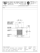
4. Refer to the dimensional drawing for cutting height of the
distributor tube. If there is no dimensional drawing, cut
the distributor tube flush with the top of the tank.
5. Lubricate the distributor o-ring seal and tank o-ring seal.
Place the main control valve on tank.
NOTE: Only use silicone lubricant.
6. Solder joints near the drain must be done prior to
connecting the Drain Line Flow Control fitting (DLFC).
Leave at least 6 inches (15 cm) between the DLFC and
solder joints when soldering pipes that are connected on
the DLFC. Failure to do this could cause interior damage
to the DLFC.
7. Plumber tape is the only sealant to be used on the drain
fitting. The drain from twin tank units may be run through
a common line.
8. Make sure that the floor is clean beneath the salt storage
tank and that it is level.
9. Place approximately 1 inch (25 mm) of water above the
grid plate. If a grid is not utilized, fill to the top of the air
check (Figure 1) in the salt tank. Do not add salt to the
brine tank at this time.
10. On units with a bypass, place in bypass position. Turn on the
main water supply. Open a cold soft water tap nearby and let
run a few minutes or until the system is free from foreign
material (usually solder) that may have resulted from the
installation. Once clean, close the water tap.
11. Slowly place the bypass in service position and let water
flow into the mineral tank. When water flow stops, slowly
open a cold water tap nearby and let run until the air is
purged from the unit.
12. Plug unit into an electrical outlet.
NOTE: All electrical connections must be connected according
to local codes. Be certain the outlet is uninterrupted.
60002 Rev E
Figure 1 Residential Air Check Valve
STARTUP INSTRUCTIONS
The water softener should be installed with the inlet, outlet, and
drain connections made in accordance with the manufacturer’s
recommendations, and to meet applicable plumbing codes.
1. Turn the manual regeneraton knob slowly in a clockwise
direction until the program micro switch lifts on top of the
first set of pins. Allow the drive motor to move the piston to
the first regeneration step and stop. Each time the program
switch position changes, the valve will advance to the next
regeneration step. Always allow the motor to stop before
moving to the next set of pins or spaces.
NOTE: For electronic valves, please refer to the manual
regeneration part of the timer operation section. If the
valve came with a separate electronic timer service
manual, refer to the timer operation section of the
electronic timer service manual.
2. Position the valve to backwash. Ensure the drain line flow
remains steady for 10 minutes or until the water runs clear
(see above).
3. Position the valve to the brine / slow rinse position. Ensure
the unit is drawing water from the brine tank (this step may
need to be repeated).
4. Position the valve to the rapid rinse position. Check the
drain line flow, and run for 5 minutes or until the water
runs clear.

4 • FLECK 2510 Service Manual
5. Position the valve to the start of the brine tank fill cycle.
Ensure water goes into the brine tank at the desired
rate. The brine valve drive cam will hold the valve in this
position to fill the brine tank for the first regeneration.
6. Replace control box cover.
7. Put salt in the brine tank.
NOTE: Do not use granulated or rock salt.
3200 TIMER SETTING PROCEDURE
How To Set Days On Which Water Conditioner Is To
Regenerate (Figure 2)
Rotate the skipper wheel until the number “1” is at the red
pointer. Set the days that regeneration is to occur by sliding
tabs on the skipper wheel outward to expose trip fingers.
Each tab is one day. Finger at red pointer is tonight. Moving
clockwise from the red pointer, extend or retract fingers to
obtain the desired regeneration schedule.
How To Set The Time Of Day
1. Press and hold the red button in to disengage the
drive gear.
2. Turn the large gear until the actual time of day is at the
time of day pointer.
3. Release the red button to again engage the drive gear.
How To Manually Regenerate Your Water Conditioner At
Any Time
1. Turn the manual regeneration knob clockwise.
2. This slight movement of the manual regeneration knob
engages the program wheel and starts the
regeneration program.
3. The black center knob will make one revolution in the
following approximately three hours and stop in the
position shown in the drawing.
4. Even though it takes three hours for this center knob to
complete one revolution, the regeneration cycle of your
unit might be set for only one half of this time.
5. In any event, conditioned water may be drawn after rinse
water stops flowing from the water conditioner drain line.
How to Adjust Regeneration Time
1. Disconnect the power source.
2. Locate the three screws behind the manual regeneration
knob by pushing the red button in and rotating the 24 hour
dial until each screw appears in the cut out portion of the
manual regeneration knob.
3. Loosen each screw slightly to release the pressure on the
time plate from the 24-hour gear.
4. Locate the regeneration time pointer on the inside of the
24-hour dial in the cut out.
5. Turn the time plate so the desired regeneration time
aligns next to the raised arrow.
6. Push the red button in and rotate the 24-hour dial.
Tighten each of the three screws.
7. Push the red button and locate the pointer one more time
to ensure the desired regeneration time is correct.
8. Reset the time of day and restore power to the unit.
61502-3200 Rev A
Figure 2
3210 TIMER SETTING PROCEDURE
Typical Programming Procedure
Calculate the gallon capacity of the system, subtract the
necessary reserve requirement and set the gallons available
opposite the small white dot on the program wheel gear
(Figure 3).
NOTE: Drawing shows 8,750 gallon setting. The capacity
(gallons) arrow (15) shows zero gallons remaining.
The unit will regenerate tonight at the set
regeneration time.
How To Set The Time Of Day
1. Press and hold the red button in to disengage the drive gear.
2. Turn the large gear until the actual time of day is opposite
the time of day pointer.
3. Release the red button to again engage the drive gear.
How To Manually Regenerate Your Water Conditioner At
Any Time
1. Turn the manual regeneration knob clockwise.
2. This slight movement of the manual regeneration knob
engages the program wheel and starts the regeneration
program.
STARTUP INSTRUCTIONS
CONTINUED

FLECK 2510 Service Manual • 5
3. The black center knob will make one revolution in the
following approximately three hours and stop in the
position shown in the drawing.
4. Even though it takes three hours for this center knob to
complete one revolution, the regeneration cycle of your
unit might be set for only one half of this time.
5. In any event, conditioned water may be drawn after rinse
water stops flowing from the water conditioner drain line.
Immediate Regeneration Timers
These timers do not have a 24-hour gear. Setting the gallons
on the program wheel and manual regeneration procedure
are the same as previous instructions. The timer will
regenerate as soon as the capacity gallons reaches zero.
NOTE: The program wheel to the left may be different than
the program wheel on the product.
NOTE: To set meter capacity rotate manual knob one - 360°
revolution to set gallonage.
61502-3200 Rev A
Figure 3
3200, 3210, 3220, 3230 REGENERATION
CYCLE SETTING PROCEDURE
How To Set The Regeneration Cycle Program
The regeneration cycle program on your water conditioner
has been factory preset, however, portions of the cycle or
program may be lengthened or shortened in time to suit local
conditions.
3200 Series Timers (Figure 4)
1. To expose cycle program wheel, grasp timer in upper
left-hand corner and pull, releasing snap retainer and
swinging timer to the right.
2. To change the regeneration cycle program, the program
wheel must be removed. Grasp program wheel and
squeeze protruding lugs toward center, lift program wheel
off timer. Switch arms may require movement to
facilitate removal.
3. Return timer to closed position engaging snap retainer in
back plate. Make certain all electrical wires locate above
snap retainer post.
Timer Setting Procedure
How To Change The Length Of The Backwash Time
The program wheel as shown in the drawing is in the service
position. As you look at the numbered side of the program
wheel, the group of pins starting at zero determines the length
of time your unit will backwash.
For example, if there are six pins in this section, the time of
backwash will be 12 min. (2 min. per pin). To change the length
of backwash time, add or remove pins as required. The number
of pins times two equals the backwash time in minutes.
How To Change The Length Of Brine And Rinse Time
1. The group of holes between the last pin in the backwash
section and the second group of pins determines the length
of time that your unit will brine and rinse (2 min. per hole).
2. To change the length of brine and rinse time, move the rapid
rinse group of pins to give more or fewer holes in the brine
and rinse section. Number of holes times two equals brine
and rinse time in minutes.
How To Change The Length Of Rapid Rinse
1. The second group of pins on the program wheel determines
the length of time that your water conditioner will rapid
rinse (2 min. per pin).
2. To change the length of rapid rinse time, add or remove pins
at the higher numbered end of this section as required. The
number of pins times two equals the rapid rinse time
in minutes.
How To Change The Length Of Brine Tank Refill Time
1. The second group of holes in the program wheel determines
the length of time that your water conditioner will refill the
brine tank (2 min. per hole).
2. To change the length of refill time, move the two pins at the
end of the second group of holes as required.
3. The regeneration cycle is complete when the outer
microswitch is tripped by the two pin set at end of the brine
tank refill section.
4. The program wheel, however, will continue to rotate until
the inner micro switch drops into the notch on the
program wheel.
61502-3210 Rev A
Figure 4
3210 TIMER SETTING PROCEDURE
CONTINUED

6 • FLECK 2510 Service Manual
37
615023200 Rev A
3200 TIME CLOCK TIMER ASSEMBLY
36
38

FLECK 2510 Service Manual • 7
Item No. QTY Part No. Description
1 ..............1 ...... 13870 ..............Housing, Timer, 3200
2 ..............1 ...... 14265 ..............Clip, Sping
3 ..............3 ...... 14087 ..............Insulator
4 ..............1 ...... 10896 ..............Switch, Micro
5 ..............1 ...... 15320 ..............Switch, Micro, Timer
6 ..............2 ...... 11413 ..............Screw, Pan Hd Mach,
4-40 x 1-1/8
7 ..............1 ...... 13886 ..............Knob, 3200
8 ..............5 ...... 13296 ..............Screw, Hex Wsh, 6-20 x 1/2
9 ..............1 ...... 11999 ..............Label, Button
10 ............1 ...... 13018 ..............Pinion, Idler
11 ............1 ...... 13312 ..............Spring, Idler Shaft
12 ............1 ...... 13017 ..............Gear, Idler
13 ............1 ...... 13164 ..............Gear, Drive
14 ............1 ...... 13887 ..............Plate, Motor Mounting
15 ............1 ...... 18743-1 ..........Motor, 120V, 60Hz, 1/30 RPM
....... 18752-1 ..........Motor, 100V, 50Hz, 1/30 RPM
....... 18824-1 ..........Motor, 230V, 50Hz, 1/30 RPM
....... 18826-1 ..........Motor, 24V, 50Hz, 1/30 RPM
....... 19659-1 ..........Motor, 24V, 60Hz, 1/30 RPM
....... 19660-1 ..........Motor, 230V, 60Hz, 1/30 RPM
16 ............2 ...... 13278 ..............Screw, Fillister Hd
6-32 x .156
17 ............1 ...... 15424 ..............Spring, Detent, Timer
18 ............1 ...... 15066 ..............Ball, 1/4-inch, Delrin
19 ............1 ...... 15465 ..............Label, Caution
20 ............1 ...... 19210 ..............Program Wheel Assy
21 ............1 ...... 13911 ..............Gear, Main Drive, Timer
22 ...........17 ..... 41754 ..............Pin, Spring, 1/16 x 5/8 SS,
Timer
23 ............1 ...... 13011 ..............Arm, Cycle Actuator
24 ............1 ...... 13864 ..............Ring, Skipper Wheel
25 ............2 ...... 13311 ..............Spring, Detent, Timer
26 ............2 ...... 13300 ..............Ball, 1/4-inch, SS
27 ............1 ...... 14381 ..............Skipper Wheel Assy, 12 Day
....... 14860 ..............Skipper Wheel Assy, 7 Day
28 ............1 ...... 13014 ..............Pointer, Regeneration
29 ............1 ...... 40096-24 .........Dial, 12 AM Regen Assy,
Black
....... 40096-02 .........Dial, 2 AM Regen Assy, Black
30 ............1 ...... 13881 ..............Bracket, Hinger Timer
31 ............2 ...... 11384 ..............Screw, Phil, 6-32 x 1/4 Zinc
32 ............1 ...... 13902 ..............Harness, 3200
33 ............2 ...... 40422 ..............Nut, Wire, Tan
34 ............1 ...... 15354-01 .........Wire, Ground, 4 inches
35 ............1 ...... 14007 ..............Label, Time of Day
36 ............1 ...... * ......................Complete 3200 Time Clock
Timer Assembly
37 ..................... 60320-02 .........Switch Kit, 3200/9000 Timer
Auxiliary, Optional
38 ..................... 61420-03 .........Program Wheel, Gear Assy,
Filter 2 Min Per Pin
....... 61420-04 .........Program Wheel, Gear Assy,
Softener, 2 Min Per Pin
*See Powerhead Ordering Guide
Item No. QTY Part No. Description
3200 TIME CLOCK TIMER ASSEMBLY
CONTINUED

8 • FLECK 2510 Service Manual
3210 METER DELAYED TIMER ASSEMBLY
41
42
61502-3210 Rev A
40
43

FLECK 2510 Service Manual • 9
Item No. QTY Part No. Description
1 ..............1 ...... 13870 ..............Housing, Timer, 3200
2 ..............1 ...... 13802 ..............Gear, Cycle Actuator
3 ..............1 ...... 40096-02 .........Dial 2 AM Regen Assy, Black
4 ..............1 ...... 13886 ..............Knob, 3200
5 ..............4 ...... 13296 ..............Screw, Hex Wsh, 6-20 x 1/2
6 ..............2 ...... 11999 ..............Label, Button
7 ..............1 ...... 13803 ..............Gear, Program Drive Wheel
8 ..............1 ...... 13806 ..............Retainer, Program Wheel
9 ..............1 ...... 13748 ..............Screw, Flat Head St,
6-20 x 1/2
10 ............1 ...... 14265 ..............Clip, Spring
11 ............1 ...... 15424 ..............Spring, Detent, Timer
12 ............1 ...... 15066 ..............Ball, 1/4-inch Delrin
13 ............1 ...... 13018 ..............Pinion, Idler
14 ............1 ...... 13312 ..............Spring, Idler Shaft
15 ............1 ...... 13017 ..............Gear, Idler
16 ............1 ...... 13164 ..............Gear, Drive
17 ............1 ...... 13887 ..............Plate, Motor Mounting
18 ............1 ...... 18743-1 ..........Motor, 120V, 60Hz 1/30 RPM
....... 18752-1 ..........Motor, 100V, 50Hz, 1/30 RPM
....... 18824-1 ..........Motor, 230V, 50Hz, 1/30 RPM
....... 18826-1 ..........Motor, 24V, 50Hz, 1/30 RPM
....... 19659-1 ..........Motor, 24V, 60Hz, 1/30 RPM
....... 19660-1 ..........Motor, 230V, 60Hz, 1/30 RPM
19 ............1 ...... 13278 ..............Screw, Fillister Hd,
6-32 x .156
20 ............1 ...... 13830 ..............Pinion, Program Wheel Drive
21 ............1 ...... 13831 ..............Clutch, Drive Pinion
22 ............1 ...... 14276 ..............Spring, Meter, Clutch
23 ............1 ...... 14253 ..............Retainer, Clutch Spring
24 ............3 ...... 11384 ..............Screw, Phil, 6-32 x 1/4
25 ............1 ...... 13881 ..............Bracket, Hinge Timer
26 ............3 ...... 14087 ..............Insulator
27 ............1 ...... 10896 ..............Switch, Micro
28 ............1 ...... 15320 ..............Switch, Micro, Timer
29 ............2 ...... 11413 ..............Screw, Pan Hd Mach,
4-40 x 1 1/8
30 ............1 ...... 14198 ..............Label, Indicator
31 ............1 ...... 15465 ..............Label, Caution
32 ............1 ...... 14007 ..............Label, Time of Day
33 ............1 ...... 14045 ..............Label, Instruction
34 ............1 ...... 13902 ..............Harness, 3200
35 ............2 ...... 40422 ..............Nut, Wire, Tan
36 ............1 ...... 15354-01 .........Wire, Ground, 4 inches
37 ............1 ...... 19210 ..............Program Wheel Assy
38 ...........17 ..... 41754 ..............Pin, Spring, 1/16 x 5/8 SS,
Timer
39 ............1 ...... 13911 ..............Gear, Main Drive, Timer
40 ............1 ...... * ......................Complete 3210 Meter
Delayed Timer Assembly
41 ..................... 60405-10 .........Program Wheel, w/3/4-inch
STD Label 0-2,100 gal
....... 60405-20 .........Program Wheel, w/3/4-inch
EXT Label 0-10,000 gal
.........60405-11 .......... Program Wheel, w/3/4-inch
STD Metric Label 0-8 m3
.........60405-21 .......... Program Wheel, w/3/4-inch
EXT Range 0-40 m3
42 ..................... 60320-02 .........Switch Kit, 3200/9000 Timer
Auxiliary, Optional
43 ..................... 61420-03 .........Program Wheel, Gear Assy,
Filter 2 Min Per Pin
....... 61420-04 .........Program Wheel, Gear Assy,
Softener, 2 Min Per Pin
*See Powerhead Ordering Guide
Item No. QTY Part No. Description
3210 METER DELAYED TIMER ASSEMBLY
CONTINUED

10 • FLECK 2510 Service Manual
3220 METER IMMEDIATE TIMER
ASSEMBLY
1
2
3
4
5
6
7
8
9
10
11
12
13
14
15
16
17
18
19
20
21
22
23
24
25
26
27
28
29
30
31
32
33
34
35
36
5
1
23
23
21
4
38
39
61502-3220 Rev B
37
40

FLECK 2510 Service Manual • 11
Item No. QTY Part No. Description
1 ..............1 ...... 13870 ..............Housing, Timer
2 ..............1 ...... 15431 ..............Gear, Cycle Actuator,
System #5
3 ..............1 ...... 13886 ..............Knob, 3200
4 ..............4 ...... 13296 ..............Screw, Hex Wsh, 6-20 x 1/2
5 ..............2 ...... 11999 ..............Label, Button
6 ..............1 ...... 13807 ..............Gear, Program Drive Wheel
7 ..............1 ...... 13806 ..............Retainer, Program Wheel
8 ..............1 ...... 13748 ..............Screw, Flt Hd St, 6-20 x 1/2
9 ..............1 ...... 14265 ..............Spring Clip
10 ............1 ...... 13018 ..............Pinion, Idler
11 ............1 ...... 18563 ..............Idler Shaft Spring
12 ............1 ...... 13017 ..............Gear, Idler
13 ............1 ...... 13164 ..............Drive Gear
14 ............1 ...... 13887 ..............Plate, Motor Mounting
15 ............1 ...... 18743-1 ..........Motor, 120V, 60 Hz, 1/30 RPM
....... 18752-1 ..........Motor, 100V, 50Hz, 1/30 RPM
....... 18824-1 ..........Motor, 230V, 50Hz, 1/30 RPM
....... 18826-1 ..........Motor, 24V, 50Hz, 1/30 RPM
....... 19659-1 ..........Motor, 24V, 60Hz, 1/30 RPM
....... 19660-1 ..........Motor, 230V, 60Hz, 1/30 RPM
16 ............2 ...... 13278 ..............Screw, Sltd Fillister Hd
17 ............1 ...... 14502 ..............Pinion, Program Wheel
18 ............1 ...... 14501 ..............Clutch, Drive Pinion
19 ............1 ...... 14276 ..............Meter Clutch Spring
20 ............1 ...... 14253 ..............Retainer, Clutch Spring
21 ............3 ...... 11384 ..............Screw, Phil, 6-32 x 1/4 Zinc
22 ............1 ...... 13881 ..............Bracket, Hinge Timer
23 ............3 ...... 14087 ..............Insulator
24 ............1 ...... 15414-00 .........Micro Switch
25 ............1 ...... 15320 ..............Switch, Micro, Timer
26 ............2 ...... 11413 ..............Screw, Pan Hd Mach,
4-40 x 1-1/8
27 ............1 ...... 14198 ..............Label, Indicator
28 ............1 ...... 15465 ..............Label, Caution
29 ............1 ...... 14007 ..............Label, Time of Day
30 ............1 ...... 15148 ..............Label, Instruction
31 ............1 ...... 40617 ..............Harness, 3220
32 ............2 ...... 40422 ..............Nut, Wire, Tan
33 ............1 ...... 15354-01 .........Wire, Ground, 4 inches
Item No. QTY Part No. Description
34 ............1 ...... 19210-05 .........Program Wheel Assembly,
9000/3230
35 ...........17 ..... 41754 ..............Pin, Spring, 1/16 x 5/8
Stainless Steel, Timer
36 ............1 ...... 15055 ..............Gear, Main Drive
37 ............1 ...... * ......................Complete 3220 Meter
Immediate Timer Assy
38 ..................... 60405-10 .........Program Wheel, w/3/4-inch
STD Label 0-2,100 gal
....... 60405-20 .........Program Wheel, w/3/4-inch
EXT Label 0-10,000 gal
....... 60405-11 .........Program Wheel, w/3/4-inch
STD Metric Label 0-8 m3
....... 60405-21 .........Program Wheel, w/3/4-inch
EXT Range 0-40 m3
39 ..................... 60320-02 .........Switch Kit, 3200/9000 Timer
Auxiliary, Optional
40 ...................... 61420-06 .........Program Wheel, Gear Assy,
Softener Immediate 2 Min
Per Pin
....... 61420-42 .........Program Wheel, Gear Assy,
Filter Immediate 2 Min
Per Pin
*See Powerhead Ordering Guide
3220 METER IMMEDIATE TIMER
ASSEMBLY
CONTINUED

2510 SXT VALVE
2510 ELECTROMECHANICAL
SOFTENER METER
2510 ELECTROMECHANICAL
SOFTENER TIME CLOCK
2510 ELECTROMECHANICAL
FILTER TIME CLOCK
2510 MANUAL VALVE
Item No. QTY Part No. Description
1 ................... 1 ......... 251006-001 ........... 2510, SOF, DNF, CLK, SXT-, 24-60,
CW 2--, .50, LES, NA2, 1650, HWBP
.......... 251006-002 ........... 2510, SOF, DNF, M34, SXT-, 24-60,
CW 1--, .50, LES, NA2, 1600, HWBP
.......... 251006-004 ........... 2510, SOF, DNF, M34, SXT-, 24-60,
CW 1--, .50, LES, NA2, 1650, HWBP
.......... 251006-005 ........... 2510, SOF, DNF, M34, SXT-, 24-60,
CW 1--, .50, LES, NA2, 1600, HWBP
.......... 251006-006 ........... 2510, SOF, DNF, M34, SXT-, 24-60,
CW 1--, .50, LES, NA2, 1600, HWBP
.......... 251006-003 ........... 2510, FIL, DNF, CLK, SXT-, 24-60,
CW BWF, BWF, LES, NA2, BWF-,
HWBP
Item No. QTY Part No. Description
1 ................... 1 ......... 251002-001 ........... 2510, SOF, DNF, M34, MDEL, 12060,
CW 1--, .50, LES, NA2, 1650, HWBP
.......... 251002-002 ........... 2510, SOF, DNF, M34, MDEL, 12060,
CW 1--, .50, LES, NA2, 1650, HWB,
.......... 251002-003 ........... 2510, SOF, DNF, M34, MDEL, 12060,
CW 2PV, .50, LES, NA2, 1600, HWB,
Item No. QTY Part No. Description
1 ................... 1 ......... 251001-002 ........... 2510, SOF, DNF, CLK, 12DA, 12060,
CW 1--, .50, LES, NA2, 1650, HWBP
.......... 251001-006 ........... 2510, SOF, DNF, CLK, 12DA, 12060,
CW 1--, .50, LES, NA2, 1650, HWBP
.......... 251001-007 ........... 2510, SOF, DNF, CLK, 12DA, 12060,
CW 2PV, .50, LES, NA2, 1600, HWBP
Item No. QTY Part No. Description
1 ................... 1 ......... 251001-001 ........... 2510, FIL, DNF, CLK, 12DA, 12060,
CW BWF, BWF, LES, NA2, BWF-,
HWBP
.......... 251001-003 ........... 2510, FIL, DNF, CLK, 12DA, 12060,
CW BWF, BWF, LES, NA2, BWF-,
HWBP
.......... 251001-008 ........... 2510, FIL, DNF, CLK, 12DA, 12060,
CW BWF, BWF, LES, NA2, BWF-,
NWBP
.......... 251000-001 ........... 2510, FIL, DNF, CLK, 7DAY, 12060,
CW BWF, BWF, LES, NA2, BWF-,
HWBP
NOTE: Above part numbers DO NOT include the following parts.
Cover
Bypass Assembly
Yoke Assembly
DLFC with Retainer
Flow Washers
See accessory page for options.
Item No. QTY Part No. Description
1 ................... 1 ......... 251011-002 ........... 2510, SOF, DNF, MAN, MAN-,
MAN--, CW 1--, MAN, LES, NA2,
MAN-, HWBP
.......... 251011-001 ........... 2510, FIL, DNF, MAN, MAN-,
MAN--, CW BWF, BWF, LES, NA2,
BWF-, HWBP
12 • FLECK 2510 Service Manual

2510 VALVE ACCESSORIES
Covers
60219-02 .....................Cover Assy, Environmental, Black
w/clear window
60219-12 .....................Cover Assy, Environmental, Black
w/black window
60232-110 ...................Cover, Designer, 1 pc. Black
60232-310 ...................Cover, Designer, Gray/Black
Bypasses
60041SS.......................1” Bypass, SS, NPT
60040SS.......................3/4” Bypass, SS, NPT
60049 ...........................Bypass, Plastic
Yokes
19620-01 .....................Yoke Assy, 3/4", r/angle, 90 deg.
18706 ...........................1" Yoke, Plastic NPT
18706-10 .....................1" Yoke, Plastic BSP
18706-02 .....................3/4" Yoke, Plastic NPT
18706-12 .....................3/4" Yoke, Plastic BSP
13708-40 .....................1” Yoke, Sweat
41026-01 .....................1” Yoke, SS, NPT
42690 ...........................3/4” Yoke, Sweat
41027-01 .....................3/4” Yoke, SS, NPT
Washers
19153 ...........................Washer, Flow, 0.6 GPM
19152 ...........................Washer, Flow, 0.8 GPM
12085 ...........................Washer, Flow, 1.2 GPM
19150 ...........................Washer, Flow, 1.3 GPM
12086 ...........................Washer, Flow, 1.5 GPM
12087 ...........................Washer, Flow, 2.0 GPM
12088 ...........................Washer, Flow, 2.4 GPM
12089 ...........................Washer, Flow, 3.0 GPM
12090 ...........................Washer, Flow, 3.5 GPM
12091 ...........................Washer, Flow, 4.0 GPM
19147 ...........................Washer, Flow, 4.5 GPM
12092 ...........................Washer, Flow, 5.0 GPM
17814 ...........................Washer, Flow, 6.0 GPM
12408 ...........................Washer, Flow, 7.0 GPM
Drain Elbows
19699 ...........................1/2" Drain Elbow, 45
13121 ...........................5/8" Drain Elbow, 90
Hose Barbs
13308 ...........................1/2" Straight Hose Barb
13308-01 .....................5/8" Straight Hose Barb
Collectors
18280 ...........................Top Collector, 1.050
18280-01 .....................Top Collector, 1.050 Wide
18280-02 .....................Top Collector, 1.050 Narrow
DLFC
60705-00 .....................DLFC, Plastic, Blank
60706-8.0 ....................DLFC, QC x 3/4”F, 8.0 GPM
60706-9.0 ....................DLFC, QC x 3/4”F, 9.0 GPM
60706-10 .....................DLFC, QC x 3/4”F, 10 GPM
60706-12 .....................DLFC, QC x 3/4”F, 12 GPM
60706-15 .....................DLFC, QC x 3/4”F, 15 GPM
BYPASS
COVER, ENVIRONMENTAL
WASHER DRAIN ELBOW
COLLECTOR
YOKE
COVER, DESIGNER
HOSE BARBS
DLFC
FLECK 2510 Service Manual • 13

2510 VALVE CONVERSION ASSEMBLIES
BLFC
60010-25 .....................BLFC, 1650, .25 GPM, Plastic
(0.75 lbs NaCl/min)
60010-50 .....................BLFC, 1650, .50 GPM, Plastic
(1.5 lbs NaCl/min)
60010-100 ...................BLFC, 1650, 1.0 GPM, Plastic
(3 lbs NaCl/min)
60020-25 .....................BLFC, .25 GPM 1600
60020-50 .....................BLFC, .50 GPM 1600
60020-100 ...................BLFC, 1.0 GPM 1600
Brine Valves
60011 ...........................Brine Valve, 1650, Less BLFC
60011-000 ...................Brine Valve, 1650, Short Stem,
0.125 GPM Less Tube
60011-010 ...................Brine Valve, 1650, Short Stem,
0.25 GPM Less Tube
60011-020 ...................Brine Valve, 1650, Short Stem,
0.50 GPM Less Tube
60011-030 ...................Brine Valve, 1650, Short Stem,
1.0 GPM Less Tube
60029 ...........................Brine Valve, 1650, Short Stem,
Brass, Less BLFC
60029-01 .....................Brine Valve, 1600, Short Stem,
Less BLFC, Less Sm Parts
60029-010 ...................Brine Valve, 1600, Short Stem, 0.25 GPM
60029-020 ...................Brine Valve, 1600, Short Stem, 0.50 GPM
60029-030 ...................Brine Valve, 1600, Short Stem, 1.0 GPM
Injector Nozzles
10913-0 .......................Nozzle, Injector, #0, Red (8” Tank)
10913-00 .....................Nozzle, Injector, #00, Violet (7” Tank)
10913-000 ...................Nozzle, Injector, #000, Brown (6” Tank)
10913-1 .......................Nozzle, Injector, #1, White (9” & 10" Tank)
10913-2 .......................Nozzle, Injector, #2, Blue (12” Tank)
10913-3 .......................Nozzle, Injector, #3, Yellow (13” Tank)
10913-4 .......................Nozzle, Injector, #4, Green (14” Tank)
10913BLK ....................Nozzle, Injector, Black (Filter)
12973-0 .......................Nozzle, Injector, #0, PVC
12973-1 .......................Nozzle, Injector, #1, PVC
12973-2 .......................Nozzle, Injector, #2, PVC
12973-3 .......................Nozzle, Injector, #3, PVC
12973-4 .......................Nozzle, Injector, #4, PVC
Injector Throats
10914-0 .......................Throat, Injector, #0, Red (8” Tank)
10914-00 .....................Throat, Injector, #00, Violet (7” Tank)
10914-000 ...................Throat, Injector, #000, Brown (6” Tank)
10914-1 .......................Throat, Injector, #1, White (9” & 10" Tank)
10914-2 .......................Throat, Injector, #2, Blue (12” Tank)
10914-3 .......................Throat, Injector, #3, Yellow (13” Tank)
10914-4 .......................Throat, Injector, #4, Green (14” Tank)
12974-0 .......................Throat, Injector, #0, PVC
12974-1 .......................Throat, Injector, #1, PVC
12974-2 .......................Throat, Injector, #2, PVC
12974-3 .......................Throat, Injector, #3, PVC
12974-4 .......................Throat, Injector, #4, PVC
BLFC BRINE VALVE
INJECTOR NOZZLE INJECTOR THROAT
14 • FLECK 2510 Service Manual

2510 VALVE CONVERSION ASSEMBLIES
Labels
14214 ..........................Label, 13K
14076 ..........................Label, 16K
13969 ..........................Label, 18K
14046 ..........................Label, 21K
13961 ..........................Label, 24K
14047 ..........................Label, 26K
14180 ..........................Label, 28K
13962 ..........................Label, 30K
14048 ..........................Label, 32K
13971 ..........................Label, 36K
14073 ..........................Label, 40K
13974 ..........................Label, 45K
14239 ..........................Label, 48K
14074 ..........................Label, 50K
14034 ..........................Label, 60K
14183 ..........................Label, 70K
Switch
60320-12 .....................Switch Kit, 1500 thru 2850 SPG Drive
Motor
Timers/Powerheads (see Powerhead/Timer Ordering Guide)
60303-XX .....................3200 7 Day Timer
60304-XX .....................3200 12 Day Timer
60306-XX .....................3200 Meter Delayed Timer
Timers
42778 ...........................Timer Assy, SXT, 2510/2750/2850
42466-01 .....................Timer Assy, XT, Right Hinged
42466-11 .....................Timer Assy, NXT, Right Hinged
Miscellaneous
60374 ...........................Flat Cap Assy, 1600
10269 ...........................Nut, Jam,, 3/4-16
43560 ...........................Fitting, Brine Valve, Steel
Meters
15495 ...........................Meter Cable, 13.87”
15307 ...........................Tube, Cable Guide, 2750
60088-180 ...................Meter Assy, 3/4” Dual Port, Slip, Std,
Rt Ang/180, Plas, Pdl, w/clps
60089-180 ...................Meter Assy, 3/4” Dual Port, Slip, Ext,
Rt Ang/180, Plas, Pdl, w/clps
60086-50 .....................Meter Assy, 3/4” Dual Port, Slip Elec,
Plas, Pdl, w/clps
19121-01 .....................Meter Cable Assy, SE, Paddle
60626 ...........................Meter Assy, Turbine, Electronic 3/4”
with clips and screws
19791-02 .....................Meter Cable Assy, Turbine/SXT
LABEL
TIMER ASSY, NXT
SWITCH
TIMERS, 3200 TIMER ASSY, SXT
TIMER ASSY, XT
METER ASSY, PADDLE
FLECK 2510 Service Manual • 15

16 • FLECK 2510 Service Manual
BR61501-1500 Rev C
POWERHEAD ASSEMBLY
(ENVIRONMENTAL)
20
19
18
16
19
20
15
3
13
18
17
19
20
23
21
22
9
5
7
11
6
10
24
25
14
2
4
1
12
9
11A
8
26
29
27
28

FLECK 2510 Service Manual • 17
Item No. QTY Part No. Description
1 1 18697-15 Backplate, Hinged
2 ..............1 ...... 11838 ..............Power Cord, 6-feet, North
American, Flat
....... 19303-01 .........Power Cord, 6-feet,
Austrailian
....... 19885-01 .........Power Cord, 6-feet,
Japanese
....... 11545-01 .........Power Cord, 6-feet,
European
3 ..............1 ...... 13547 ..............Strain Relief, Cord
4 ..............1 ...... 40400 ..............Harness, Drive Designr/
Envirmtl
5 ..............2 ...... 10231 ..............Screw, Slot Hex
1/4-20 x 1/2 35 in-lbs ±20%
6 ..............2 ...... 10218 ..............Switch, Micro
7 ..............1 ...... 10909 ..............Pin, Connecting Rod Spring
8 ..............1 ...... 60160-15 .........Drive Cam Assy, STF, Blue,
2900
9 ..............2 ...... 10338 ..............Pin, Roll, 3/32 x 7/8
10 ............2 ...... 14923 ..............Screw, Pan Hd MACH, 4-40
x 1 5.0 in-lbs ±10%
11 ............1 ...... 41543 ..............Motor, Drive, 115V/60 Hz
....... 41545 ..............Motor, Drive, 220V,
50-60Hz, SP, Fam 1
11A ................... 42579 ..............Motor, Drive, 24 VAC/DC,
50-60 Hz, Fam 1
12 ............1 ...... 12777 ..............Cam, Shut-off Valve
13 ............2 ...... 10300 ..............Screw, Hx Wash Head,
8 x 3/8 20 in-lbs ±20%
14 ............1 ...... 3200 ................Timer Assy, 3200 7 or
12 Day
................................3210 Meter Delay
................................3220 Meter Immediate
15 ............1 ...... 15806 ..............Hole Plug, (HeyCo)
16 ............1 ...... 16493 ..............Plug, Hole, HeyCo, .88 Dia
17 ............1 ...... 17421 ..............Plug, 1.20 Hole
18 ............2 ...... 19691 ..............Plug, .750 Dia. Hole, Flush
19 ............7 ...... 19800 ..............Plug (Hole Size: Dia .140)
20 ............4 ...... 19801 ..............Plug, Dia .190
21 ............1 ...... 43560 ..............Fitting, Brine Valve
(Used on Filter Valves)
22 ............1 ...... 10269 ..............Nut, Jam, 3/4-16 (Used on
FIlter Valves)
Wrench Tighten
23 ............2 ...... 41581 ..............Plug, Hole .125 Dia, White
24 ............1 ...... 10872 ..............Screw, Hex WSH, 8-32 x 5/16
20 IN-LBS ±20%
25 ............1 ...... 14202-01 .........Screw, Hex Washer #8-32 x
5/16 Hand Tighten
26 ............1 ...... 60219-02 .........Cover Assy, Environmental,
Black, Clear Window
....... 60219-12 .........Cover Assy, Environmental,
Black, Black Window
27 ............1 ...... * ......................Powerhead Assembly
28 ............1 ...... 60050-23 .........Drive Motor Assy, 24 VAC/
DC, 50-60 Hz FAM 1
....... 60050-21 .........Drive Motor Assy, 115V/60 Hz
....... 60050-22 .........Drive Motor Assy, 220V,
50-60 Hz SP FAM1
29 ..................... 60320-12 .........Switch Kit, 1500-2850 Drive
Motor
Not Shown:
1 ...... 15441 ..............Cable Guide Assy, 2510
1 ...... 15495 ..............Meter Cable, 13.87 inches
*See Powerhead Ordering Guide
Item No. QTY Part No. Description
POWERHEAD ASSEMBLY
(ENVIRONMENTAL)
CONTINUED

18 • FLECK 2510 Service Manual
MANUAL POWERHEAD ASSEMBLY
Item No. QTY Part No. Description
1 ..............1 ...... 12593 ..............Backplate, Manual
2 ..............1 ...... 12592 ..............Bracket, Lever Position
3 ..............1 ...... 12596 ..............Screw, Spec Mach,
1/4 - 20 x 1/2
4 ..............1 ...... 12707 ..............Washer, Spring
5 ..............1 ...... 11235 ..............Nut, Hex, 1/4 - 20, Mach
Screw, Zinc
6 ..............1 ...... 12594 ..............Lever, Valve Position
7 ..............2 ...... 10231 ..............Screw, Slot Hex,
1/4 - 20 x 1/2 18-8 SS
8 ..............1 ...... 60224-32 .........Cover Assy, Manual, Filter
1 ...... 60224-33 .........Cover Assy, Manual,
Softener
9 ..............4 ...... 10300 ..............Screw, Slot Hex Wsh, 8-18
x 3/8 Type “B” RC44-47
10 ..................... 60409 ..............Powerhead Assy, Manual
Not Shown:
1 ...... 10909 ..............Pin, Link
60409 Rev A
5
8
9
7
1
4
3
2
6
10

FLECK 2510 Service Manual • 19
22
23
25
2
15
6
13
9
12
8
11
1
24
5
18
19
17
30
20
29
21
10
4
3
14
16
7
32
31
35
36
36
36
36
37
37
27
34
33
61500-2510 Rev B
CONTROL VALVE ASSEMBLY
Item No. QTY Part No. Description
1 ..............1 ...... 19328 ..............Valve Body, 2510
2 ..............1 ...... 11385-01 .........Housing, Flow Control,
Plastic
3 ..............1 ...... 11183 ..............O-ring, -017
4 ..............1 ...... 12408 ..............Washer, Flow, 7.0 GPM
5 ..............1 ...... 18312 ..............Retainer, Drain
6 ..............1 ...... 19322 ..............Adapter Base, 2510
7 ..............1 ...... 19936 ..............Seal, 2510, Base
8 ..............1 ...... 19899 ..............Clamp, Female, 2510
9 ..............1 ...... 19900 ..............Clamp, Male, 2510
10 ............1 ...... 40000 ..............Pin, Hinge, Clamp
11 ............1 ...... 19998 ..............Pivot, Clamp, 2510
12 ............1 ...... 40057 ..............Screw, Comb Hd, 114-20,
2-inch
13 ............1 ...... 19197 ..............Ring, Slip
14 ............1 ...... 18303 ..............O-ring, -336
15 ............1 ...... 13030 ..............Retainer, Dist Tube, O-ring
16 ............1 ...... 13304 ..............O-ring, -121
17 ............1 ...... 17776 ..............Body, Injector, 1600
18 ............1 ...... 10328 ..............Fitting, Elbow, 90 Deg.
1/4-inch NPT x 3/8-inch Tube
19 ............1 ...... 16221 ..............Disperser, Air
20 ............1 ...... 10227 ..............Screen, Injector
21 ............1 ...... 10229 ..............Gasket, Injector Cap, 1600
22 ............1 ...... 11893 ..............Cap, Injector, SS
23 ............2 ...... 10692 ..............Screw, Slot Hex Hd,
10-24 x 1-5/8-inch
24 ............1 ...... 14805 ..............Gasket, Injector Body,
1600/1700
Item No. QTY Part No. Description

20 • FLECK 2510 Service Manual
CONTROL VALVE ASSEMBLY
CONTINUED
Item No. QTY Part No. Description
25 ............1 ...... 12338 ..............Fitting, Elbow, 90 Deg.
1/2-inch NPT x 1/2-inch
Barb
26 ............1 ...... 11893 ..............Cap, Injector, Stainless
Steel
....... 10228 ..............Cap, Injector, Brass
27 ............1 ...... 15137 ..............Screw, Hex Wsh Mach,
10-24 x 3/8
28 ............1 ...... 10757 ..............Spacer, End
29 ............1 ...... 12973-0 ..........Nozzle, Injector, #0, PVC
....... 12973-1 ..........Nozzle, Injector, #1, PVC
....... 12973-2 ..........Nozzle, Injector, #2, PVC
....... 12973-3 ..........Nozzle, Injector, #3, PVC
....... 12973-4 ..........Nozzle, Injector, #4, PVC
....... 10913-000 .......Nozzle, Injector, #000
Brown
....... 10913-00 .........Nozzle, Injector, #00 Violet
....... 10913-0 ..........Nozzle, Injector, #0 Red
....... 10913-1 ..........Nozzle, Injector, #1 White
....... 10913-2 ..........Nozzle, Injector, #2 Blue
....... 10913-3 ..........Nozzle, Injector, #3 Yellow
....... 10913-4 ..........Nozzle, Injector, #4 Green
30 ............1 ...... 12974-0 ..........Throat, Injector, #0, PVC
....... 12974-1 ..........Throat, Injector, #1, PVC
....... 12974-2 ..........Throat, Injector, #2, PVC
....... 12974-3 ..........Throat, Injector, #3, PVC
....... 12974-4 ..........Throat, Injector, #4, PVC
....... 10914-000 .......Throat, Injector, #000
Brown
....... 10914-00 .........Throat, Injector, #00 Violet
....... 10914-0 ..........Throat, Injector, #0 Red
....... 10914-1 ..........Throat, Injector, #1 White
....... 10914-2 ..........Throat, Injector, #2 Blue
....... 10914-3 ..........Throat, Injector, #3 Yellow
....... 10914-4 ..........Throat, Injector, #4 Green
31 ............1 ...... 60480-000 .......Injector Assy, 1600 #00,
Plastic
....... 60480-00 .........Injector Assy, 1600 #0,
Plastic
....... 60480-01 .........Injector Assy, 1600 #1,
Plastic
....... 60480-02 .........Injector Assy, 1600 #2,
Plastic
....... 60480-03 .........Injector Assy, 1600 #3,
Plastic
....... 60480-04 .........Injector Assy, 1600 #4,
Plastic
32 ............1 ...... 60705-00 .........DLFC, Plastic Blank
....... 60705-06 .........DLFC, Plastic 0.60 gpm
....... 60705-08 .........DLFC, Plastic 0.80 gpm
....... 60705-10 .........DLFC, Plastic 1.0 gpm
....... 60705-12 .........DLFC, Plastic 1.2 gpm
....... 60705-13 .........DLFC, Plastic 1.3 gpm
....... 60705-15 .........DLFC, Plastic 1.5 gpm
....... 60705-17 .........DLFC, Plastic 1.7 gpm
....... 60705-20 .........DLFC, Plastic 2.0 gpm
....... 60705-24 .........DLFC, Plastic 2.4 gpm
....... 60705-30 .........DLFC, Plastic 3.0 gpm
....... 60705-35 .........DLFC, Plastic 3.5 gpm
....... 60705-40 .........DLFC, Plastic 4.0 gpm
....... 60705-45 .........DLFC, Plastic 4.5 gpm
....... 60705-50 .........DLFC, Plastic 5.0 gpm
....... 60705-60 .........DLFC, Plastic 6.0 gpm
....... 60705-70 .........DLFC, Plastic 7.0 gpm
....... 60706-8.0 ........DLFC, QC x 3/4-inch F,
8.0 gpm
....... 60706-9.0 ........DLFC, QC x 3/4-inch F,
9.0 gpm
....... 60706-10 .........DLFC, QC x 3/4-inch F,
10 gpm
....... 60706-12 .........DLFC, QC x 3/4-inch F,
12 gpm
....... 60706-15 .........DLFC, QC x 3/4-inch F,
15 gpm
....... 60706-20 .........DLFC, QC x 3/4-inch F,
20 gpm
33 ............1 ...... 61670-01 .........Piston Kit, 2510/2750
....... 62044 ..............Piston Kit, 2750, Hot Water
34 ............1 ...... 61670-02 .........Piston Kit, 2510/2750,
NHWBP
35 ............2 ...... 19228-01 ......... Adapter Assy, Coupling
w/O-ring
36 ............4 ...... 13305 ..............O-ring, -119
37 ............1 ...... 14805 ..............Gasket, Injector Body,
1600/1700
Not Shown
1 ...... 11098 ..............Stuffer Tool Assy, 2510/2750
1 ...... 13061 ..............Puller Assy, Port Ring
2510/2750
1 ...... 12874 ..............Hook, Seal
Item No. QTY Part No. Description
/