Danfoss VLT® Freq. Convert. UniOP operater panel User guide

Type
User guide

This manual is also suitable for

VLT
®
frequency converters and UniOP operator panels
1
MN.90.H1.02 - VLT is a registered Danfoss trademark
VLT frequency converters and UniOP operator
panels
EXOR UniOP operator panels now have built-in
Danfoss FC protocol which means that all Danfoss
VLT frequency converters can be connected to
UniOP operator panels. This again means that you
can control VLT 2800, VLT 5000, VLT 6000 and
FCM 300 Drivemotor from one operator panel, as all
of Danfoss VLT frequency converters have the built-
in FC protocol.
The Master (UniOP operator panel) is able to send
reference, control word (start/stop) and new
parameter settings to each connected VLT
frequency converter. At the same time an actual
output frequency, output current or torque can be
read from the operator panel.
Communication Setup
Set the following parameter in the VLT frequency
converter in order to establish the communication
between the VLT frequency converter and UniOP
operator panel.
· Allocate an address in the serial communication
network to each VLT frequency converter in
parameter 500 Address.
The address in VLT 6000 is set in parameter 501
Address.
· The parameter 501 "Baud rate" is the
programmed speed at which data is transmitted
via serial communication. Set the baudate
to 9600 baud.
The baudrate in VLT 6000 is set in parameter 502
Baudrate.
· Choose FC protocol in parameter 512
Protocol.
The protocol select is by VLT 6000 done in
parameter 500 Protocol.
Connect terminal 12 (+24 VDC) to terminal 27 on
the control card.
VLT 2800
Slave 1
VLT 5000
Slave 2
VLT 6000
Slave 3
FCM 300
Slave 4
Address 1 Address 2 Address 3 Address 4
Danfoss Drives
Output frequency: 45,7 Hz
No warning or Alarm
EXOR UniOP
Operator
Interface
Two wire RS 485
UniOP operator panel
ETR 16
Abstract
This application note describes how to setup the
communication between Danfoss VLT frequency
converter and UniOP operator panels.
This note will describe how to:
Change a parameter setting
Send a reference
Send a start command
Setup dynamic text via the status word
Recipe function
If the VLT frequency converter is experiencing a
warning or an alarm, the operator panel can display
it with a text. A warning or an alarm can be saved
in the operator panel with the reason and the time
for the warning, for example High frequency
warning, Tuesday 06.04.1999, 14.03 hrs.
The installation between the operator panel and
each VLT frequency converter is done with a two-
wire RS-485 cabel.
2
MN.90.H1.02 - VLT is a registered Danfoss trademark
VLT
®
frequency converters and UniOP operator panels
Cable description
The drawing shows the connection between the
UniOP operator panel and Danfoss VLT frequency
converter.
Design of operator panel
UniOP panels are programmed with its program-
ming software called Designer, which is a
Windows
TM
based software.
The software is based on „what you see is what
you get“, which means what you see on your PC
screen is what you will actually see on your panel
display.
To program an operator panel you have to connect
UniOP to a personal computer running Designer.
The Designer project will be downloaded to the
panel via the PC serial communication port.
NB!:
Please note that the operator panel must
be in Configuration mode to be
programmed.
See UniOP Installation Guide.
To communicate with a Danfoss VLT frequency
converter you have to choose Danfoss FC as a
driver.
This is done in Project and Change controller driver.
By Installed drivers choose Danfoss FC.
Then you have to choose which operator panel you
use.
This is done in Project and Panel Setup.
Write to a parameter
The following example will teach you what to do in
order to insert parameter 207 Ramp up time 1 in the
UniOP operator page. When the program has been
downloaded to operator panel it will be possible to
write and read parameter 207 Ramp up time 1 via
the operator panel.
First of all write a description for par. 207, for
example Par. 207 Ramp up time 1.
To write or read a parameter in the VLT frequency
converter you have to create a datafield, i.e. place
the cursor after the description text for par. 207.
Click on Numeric Field or double click on a free
space of the page and the Define Field dialog box
will appear.
In Danfoss FC series you can setup the attributes,
min and max values to each parameter. The MIN
and MAX limits are assignable for each parameter.
Because we are going to access to parameter 207,
select Parameter as Data Type and insert 207 as
Address Offset.
1
14
6
68
69
UniOP
VLT
RS 485
Cable
CHA +
CHA -
P +
N -
Description text
Datafield
VLT
®
frequency converters and UniOP operator panels
3
MN.90.H1.02 - VLT is a registered Danfoss trademark
In order to have the right readout on the operator
panel, the following must be setup in Danfoss FC
series, please also have a look at parameter 207
Ramp up time 1 in the VLT 5000 Operating
Instructions:
· Data format = DBLE WORD(BIN). The data
format will be two words.
· Display format = Numeric and Unsigned.
Numerical readout on the operator panel and
no negative value can be written from the
operator panel to the VLT frequency converter.
· Numeric database = Decimal. You can write
and read decimal numbers in parameter 207
Ramp up time 1.
· Data Access = Read/write. Parameter 207
Ramp up time 1 can now both be written to and
the value can be read from the operator panel.
· Field Width/Heigth = 7 / 1. Set the width to 7
as the ramp up time can be 1458.50 sec.
· Fixed point = 2. There are two digits after the
decimal point. See the Operating Instructions.
· Min. Value = 3.00. Here you can set a
minimum value that can be sent from the
operator panel to the VLT frequency converter.
The value can be no less than the parameter
minimum value, here 0.05 sec.
· Max. Value = 3600.00. Here you can set a
maximum value that can be sent from the
operator panel to the VLT frequency converter.
The value can not be larger that the parameter
maximum value, here 3600 sec.
Press OK and download the program to the
operator panel.
The value of parameter 207 Ramp up time 1 can
now be adjusted via the Operator Panel. If the
parameter value changes, its value can be
displayed on UniOP screen as well.
The control word is used for transmitting commands
from the master (operator panel) to a slave (VLT
frequency converter).
The control word in FC protocol looks like this:
Bit Bit = 0 Bit = 1
00 Preset ref. LSB
01 Preset ref. MSB
02 DC braking
03 Coasting stop
04 Quick stop
05 Freeze output frequency
06 Ramp stop Start
07 Reset
08 Jog
09 Ramp 1 Ramp 2
10 Data not valid Data valid
11 Activate relay 01
12 Activate relay 04
13 Choice of Setup LSB
14 Choice of Setup MSB
15 Reversing
Please have a look at the Operating Instructions for
further description of each bit.
A start command can be setup in the Designer
software via the control word, for the VLT frequency
converter to start when the start button is pressed
on the operator panel. The start button can be
programmed as a touch screen button (require a
touch screen panel) or as a function button on the
operator panel. This example shows with a touch
screen button.
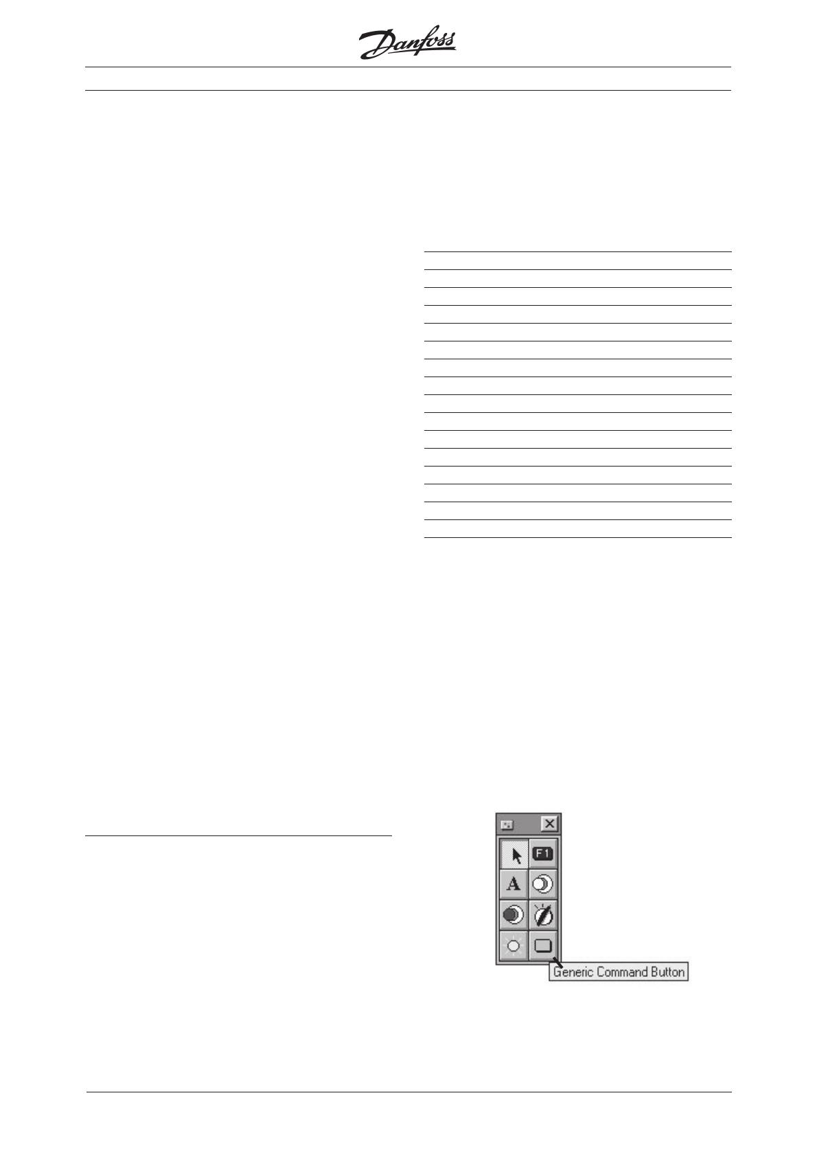
The touch screen button is being setup if you
choose Generic Command Button.
Control word
4
MN.90.H1.02 - VLT is a registered Danfoss trademark
VLT
®
frequency converters and UniOP operator panels
Control word, cont.
In the dialog box Configure Touchscreen cell you
can configurate the touch screen button.
After you have pressed Generic Command buttom,
a new dialog box is shown on the screen where you
can configurate buttons on the operator panel.
Under Cell functionality choose Macro command
and press Configure selected function.
From Define / Edit Macro Command it is possible to
choose between different commands when the
touch screen button is activated. You can for
example Go to page..., show an alarm list or print
out a report. For instance the macro Go to Page
can be used to display a particular page on the
panel.
To write to the control word in the VLT frequency
converter you shall choose Write to controller and a
new dialog box comes up.
As Datatype choose Control word and press OK.
To start the VLT frequency converter you have to
write 047C Hex in the control word, see schedule
on the previous page. To write to the operator panel
you need to convert the hexadecimal number to
decimal, so 047C Hex will be 1148 decimal.
Bit 15 14 13 12 11 10 9 8 7 6 5 4 3 2 1 0
Start (hex) 0 4 7 C
Stop (hex) 0 4 3 C
By Edit / view you can write a text on the touch
screen button.
Press on OK in Configure Touchscreen cell and after
the program is downloaded to the operator panel
the VLT frequency converter will receive a start
commando when the touch screen button is
activated.
Press OK twice.
Write the start commando 1148 in the dialog box
Macro parameter value. When the start button is
activated, the operator panel will send a control
word with the start command to the VLT frequency
converter.
VLT
®
frequency converters and UniOP operator panels
5
MN.90.H1.02 - VLT is a registered Danfoss trademark
Bus reference
To write a reference to the VLT frequency converter
you have to create a datafield, i.e. place the cursor
where you want the bus reference and click on
Numeric field.
Click on Numeric field and Danfoss FC series comes
up.
Under Data type choose Bus reference and set the
following parameters:
· Display format = Numeric and signed. Numeric
read-out on the operator panel and a negative
bus reference can be sent from the operator
panel to the VLT frequency converter.
· Numeric database = Decimal. You can write
and read decimal numbers via the bus
reference.
· Data Access = Read/write. The bus reference
can now be written to the VLT frequency
converter and can also be readen from the
operator panel.
· Field Width/Heigth = 6 / 1. Set the width to 6
because the bus reference data can be
-114.5%.
· Fixed point = 1. There is one decimal after the
comma. See the Operating Instructions.
· Min. Value = -200.0. Here you can set a
minimum bus reference that can be written
from the operator panel to the VLT frequency
converter.
· Max. Value = 200.0. Here you can set a
maximum bus reference that can be written
from the operator panel to the VLT frequency
converter.
Press OK and download the program to the
operator panel.
The bus reference can now be changed via the
operator panel.
Text message field
With text message field it is possible to give
messages to the user via the operator panel. If you
want a text telling you if the VLT frequency
converter is Running or Not Running, this can be
done by Text message Field. Use the status word in
FC protocol.
The status word is used for informing the master
(operator panel) about the conditions of the slave
(VLT frequency converter).
The status word in FC protocol looks like this:
Bit Bit = 0 Bit = 1
00 Control not ready Ready
01 VLT not ready VLT ready
02 Coasting Enable
03 No trip Trip
04 Reserved
05 Reserved
06 Reserved
07 No warning Warning
08 Speed ref. Speed = ref.
09 Local control Bus control
10 Out of frequency range Frequency OK
11 Not running Running
12 No function No function
13 Voltage OK Voltage warning
14 Torque OK Above torque limit
15 Timer limit Thermal warning
To make a Text message Field you have to create
a datafield, i.e. place the cursor where you want the
text and click on Text message Field.
Description text
Datafield
6
MN.90.H1.02 - VLT is a registered Danfoss trademark
VLT
®
frequency converters and UniOP operator panels
Under Data type choose Status word and set the
following parameters:
· Data format = Bit. The text Not running and
running is controlled by bit 11 in the status word.
· Bit index = 0B. Choose bit 11 to control the text.
· Min. Value = 0. Minimum value for bit 11.
· Max. Value = 1. Maximum value for bit 11.
By Edit message and in Message editor write the
text when bit 11 is ‘0’ and ‘1’, respectively.
Press OK and download the program to the
operator panel.
The text will now change if you start and stop the
VLT frequency converter.
Instead of changing text you can also change
graphic pictures by chosing Dynamic graphic.
Recipe function
The recipe function makes it possible to send a
complete set of parameters to the VLT frequency
converter with one command.
This is a useful feature if you have to change
parameter settings often.
First step is to activate the Recipe function.
Next you have to create a Recipe group, which can
include a new reference, control word and different
parameter settings.
Create a field for Bus reference and one for a
parameter as shown earlier. Notice that the data
field now is indicated with a R.
Next step is to create a function that controls the
different settings that Bus reference and a
parameter might have.
Activated Control variable.
Write for example Parameter set and click on
Numeric field.
VLT
®
frequency converters and UniOP operator panels
7
MN.90.H1.02 - VLT is a registered Danfoss trademark
Recipe function, cont.
Under Data type select Parameter set select and
set the following parameters:
· Min. Value = 1
· Max. Value = 5
It means that you can choose between 5
parameter settings.
Now you can create the table with the 5 different
parameter settings.
Select Page and Recipe configuration.
Set Number of parameter sets to 5.
In Recipe Item there are two predefined variable
Bus reference and Parameter 207 which can be set
to 5 different values.
Press OK after you have added some values to
each recipe item.
The last step in the Recipe function is to create a
“Send“ button to download the parameter settings
to the VLT frequency converter.
The touch screen “Send“ button is setup if you
choose Generic Command Button.
Under Cell functionality choose Macro command
and press Configure selected function.
Choose Recipe control under Define / Edit macro
command.
Under Recipe Upload / download / Select parameter
Set select download and write the page that you
are currently on, here 1. Write 0 in Parameter set.
Press OK three times.
8
MN.90.H1.02 - VLT is a registered Danfoss trademark
VLT
®
frequency converters and UniOP operator panels
Recipe function, cont.
The screen now looks like this:
Download the program to the operator panel.
Bus reference and parameter 207 can now be
changed according to the schedule by changing the
parameter set number (from 1-5).
When the “Send“ button is pressed the parameter
in the VLT frequency converter will change.
  • Page 1 1
  • Page 2 2
  • Page 3 3
  • Page 4 4
  • Page 5 5
  • Page 6 6
  • Page 7 7
  • Page 8 8

Danfoss VLT® Freq. Convert. UniOP operater panel User guide

Type
User guide
This manual is also suitable for

Ask a question and I''ll find the answer in the document

Finding information in a document is now easier with AI