
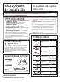
PART QUANTITY
Trim Frame 1
Bottom Duct 1
Top Bracket 1
Phillips Round-Head
24
Screws
(21 or 22 required
for installation)
Phillips Flat-Head 5
Screws (4 required
for installation)
Anti-Tip Bracket 1
Bottom Bracket 1
Template 1
PARTS INCLUDED
Questions? Call GE Answer Center at 800.626.2000 or Visit our Website at: www.GEAppliances.com
READ CAREFULLY.
KEEP THESE INSTRUCTIONS
.
Installation Built-In Trim Kits
Instructions
JX7227 and JX7230
Read these instructions completely and carefully.
IMPORTANT – Save these
instructions for local inspector’s use.
IMPORTANT – Observe all
governing codes and ordinances.
Note to Installer – Be sure to leave these
instructions with the Consumer.
Note to Consumer – Keep these instructions for
future reference.
For easier installation and personal safety, we recommend
that two people install this microwave oven.
Unplug the microwave oven before attempting
installation of this kit.
BEFORE YOU BEGIN
Skill level – Installation of this appliance requires basic
mechanical and electrical skills.
Completion time – 1-3 hours
Proper installation is the responsibility of the installer.
Product failure due to improper installation is not
covered under the Warranty.
This kit is UL listed for installation alone or over
any General Electric/Hotpoint single electric wall oven.
TOOLS YOU WILL NEED
#2 Phillips
screwdriver
Pencil
Tape measure
Awl or punch
Drill with
7
ø64” bit or #35
1
FOR YOUR SAFETY:
WARNING – Before beginning the
installation, switch power off at service panel and lock
the service disconnecting means to prevent power from
being switched on accidentally. When the service
disconnecting means cannot be locked, securely fasten
a prominent warning device, such as a tag, to the
service panel.
Scissors (optional)

2
CUTOUT DIMENSIONS
* Min. depth with receptacle outside cabinet 19
1
ø2”
Min. depth with receptacle inside cabinet 22”
Installation Instructions
Models 27” 30”
Height 16
3
ø4” 16
3
ø4”
Width 25
1
ø2” 25
1
ø2”
Depth (min.)* 19
1
ø2” or 22” 19
1
ø2” or 22”
On 27” models, allow 1
1
ø4” at the top,
9
ø16” on the sides
and 1” at the bottom for overlap of the Trim Frame over
the edges of the cutout.
On 30” models, allow 1
1
ø4”at the top, 2
1
ø8” on the sides
and 1”at the bottom for overlap of the Trim Frame over
the edges of the cutout.
For ADA Compliance, the microwave must be installed
no higher than 36
1
ø4”.
Depth
Height
1
”overlap
Width
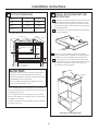
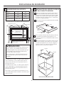
INSTALL BOTTOM BRACKET AND
BOTTOM DUCT
2
Fit the tab on the bottom bracket into the slot on the
back of the bottom duct, and push down until the
bracket is flush with the bottom of the duct. Fasten
the bottom bracket to the bottom duct by using two
round-head screws.
Disconnect the microwave oven before proceeding
with the installation.
Remove any loose items inside the microwave
oven, including the turntable and turntable support.
Carefully turn the microwave oven upside down.
Line up the tabs on the bottom duct with the slots
on the bottom of the microwave and insert the tabs
into the slots. Secure the bottom duct with four
round-head screws as shown.
A
C
B
D
Front
Rear
Screws
Screws
Screws
Microwave Oven Upside Down
1
1
1
ø4” overlap
1
” Clearance
beyond Trim Frame
(on all sides)
27
” Models:
9
ø16”overlap
30” Models: 2
1
ø8” overlap
3
” min.
CAUTION
This trim kit uses air flow from the top, bottom and
sides of the trim frame. Blocking the air flow can
cause the microwave to function improperly and may
cause damage to the microwave.
Allow a 1” clearance beyond the edge of the Trim
Frame to provide proper air flow.

3
Installation Instructions
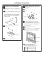
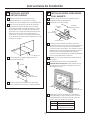
INSTALL THE ANTI-TIP BRACKET
3
Draw a line on the cutout floor at the center of the
cutout, and extend the line
1
ø2”down the face of the
cabinet.
Fold or cut the front edge of the template, along the
front guide line. Place the template flush along the
front edge of the cutout floor, aligning the center
line of the template with the center line of the cutout
floor. Mark the centers of the two screw holes with
an awl or center punch for the anti-tip bracket
location as shown.
Remove the template and drill two holes for the
anti-tip bracket.
Install the anti-tip bracket onto the cutout floor
using two round-head screws.
A
B
C
Cutout Floor
Screws
Anti-Tip Bracket
D
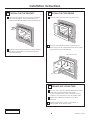
INSTALL MICROWAVE OVEN INTO
CABINET
4
Slide the microwave oven part way into the cabinet
opening.
Plug in the microwave oven.
The bottom bracket must be flat to the cutout
floor to engage correctly with the anti-tip bracket
as shown. Carefully slide the microwave oven
back, engaging the anti-tip bracket. Make sure the
power cord is not mashed or cut as you slide the
microwave into place.
Center the microwave oven within the
cutout opening.
Ensure the microwave oven is accurately centered.
Line up the center line on the cabinet with the
triangular hole on the front of the bottom duct.
Drill pilot holes through the positioning flange and
then install five round-head screws
at the front of the bottom duct as shown.
A
B
C
Anti-Tip Assembly
Bottom Duct
Bottom Bracket
Anti-Tip
Bracket
D
E
Cutout Opening
Screws
F
Positioning
Flange
Screw Models
4 JX7227SFSS, JX7230SFSS
5 JX7227DFBB, JX7227DFWW,
JX7230DFBB, JX7230DFWW

4
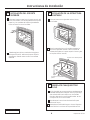
Installation Instructions
Place the top bracket on the top of the microwave
oven, with the tabs on the top and sides of the
bracket fitting squarely against the microwave oven.
Drill pilot holes through the holes in the top bracket.
Attach the top bracket to the cabinet using nine
round-head screws.
A
B
INSTALL THE TOP BRACKET
5
Your trim kit is now fully installed. Replace any loose
items that were removed from the inside
of the microwave oven. Save or discard the extra
screws. Do not place them in the microwave oven.
Keep these installation instructions for future
reference.
Replace house fuse or close circuit breaker to
restore power at the service panel.
A
B
REPLACE ANY LOOSE ITEMS
7
JX7227 and JX7230
49-40697
06-13 GE
Printed in China
C
Place the trim frame over the microwave oven.
Open the microwave oven door. Secure the trim
frame using four flat-head screws (two on the inside
top and two on the inside bottom).
A
INSTALL THE TRIM FRAME
6
B
Flat-head screws
Screws
Flat-head screws

PIEZA CANTIDAD
Estructura Ajustable
1
Conducto Inferior 1
Soporte Superior 1
Tornillos Phillips con
24
Cabeza Redonda
(
Se requieren 21 o 22
para la instalación)
Tornillos Phillips con
5
Cabeza Plana
(se requieren 4 para
la instalación)
Soporte Antivolcaduras
1
Soporte Inferior 1
Plantilla 1
PIEZAS INCLUIDAS
¿Preguntas? Llame a un Centro de Consultas de GE comunicándose al 800.626.2000 o visite
nuestro sitio web en: www.geappliances.com
LEA DETENIDAMENTE.
CONSERVE ESTAS INSTRUCCIONES
.
Instrucciones Kits Ajustables para Empotrar
de Instalación
JX7227 y JX7230
Lea estas instrucciones en su totalidad y atentamente.
IMPORTANTE – Conserve estas
instrucciones para uso del inspector local.
IMPORTANTE – Cumpla con todos los
códigos y ordenanzas gubernamentales.
Nota para el Instalador – Asegúrese de que el
Comprador conserve estas instrucciones.
Nota para el Comprador –Conserve estas
instrucciones para referencia futura.
Para una instalación más fácil y para su seguridad
personal, recomendamos que la instalación del horno
microondas sea realizada por dos personas.
Desenchufe el horno microondas antes de intentar
instalar este kit.
ANTES DE COMENZAR
Nivel de habilidad – La instalación de este
electrodoméstico requiere un nivel básico de habilidades
mecánicas.
Tiempo de instalación – Aproximadamente entre 1 y 3
horas.
La correcta instalación del producto es responsabilidad
del instalador.
Si se producen fallas en el producto debido a una
instalación inadecuada, la Garantía no cubrirá las
mismas.
(VWHNLWILJXUDHQODOLVWDGH8/VyORSDUDLQVWDODFLyQ
y sobre cualquier horno eléctrico simple de pared de
General Electric/Hotpoint.
HERRAMIENTAS QUE NECESITARÁ
Destornillador
Phillips nº2
Lápiz
Cinta métrica
Punzón o perforadora
7DODGURFRQEURFDGHøµ
o nº 35
1
PARA SU SEGURIDAD:
ADVERTENCIA – Antes de comenzar
con la instalación, apague el interruptor del panel del
servicio y bloquee el suministro del servicio a fin de
evitar que la corriente se active en forma accidental.
Cuando el suministro del servicio no pueda ser
bloqueado, coloque de forma segura un objeto de
advertencia que sea visible, tal como una etiqueta, al
panel del servicio.
Tijeras (opcional)

2
DIMENSIONES DEL RECORTE
3URIXQGLGDGPtQLPDFRQHOUHFHSWiFXORIXHUDGHOJDELQHWHòµ
3URIXQGLGDGPtQLPDFRQHOUHFHSWiFXORGHQWURGHOJDELQHWHµ
Instrucciones de Instalación
Modelos 27µ 30µ
$OWXUD
3
ø4µ
3
ø4µ
Ancho 25
1
ø2µ 25
1
ø2µ
Profundidad (mín.)*
19
1
ø2µ o 22µ 19
1
ø2µ o 22µ
(QPRGHORVGHµGHMHóµVREUHODSDUWHVXSHULRU
µDFDGDODGR\µHQODSDUWHLQIHULRUSDUDOD
superposición de la estructura ajustable sobre los
extremos del recorte.
(QPRGHORVGHµGHMHóµVREUHODSDUWHVXSHULRU
µDFDGDODGR\µHQODSDUWHLQIHULRUSDUDOD
superposición de la estructura ajustable sobre los
extremos del recorte.
Para cumplir con las disposiciones de ADA, el horno
microondas deberá estar instalado a una altura que no
VXSHUHORVóµ
Profundidad
Altura
Superposición
GHµ
Ancho
INSTALACIÓN DEL SOPORTE INFERIOR
Y DEL CONDUCTO INFERIOR
2
Enganche la lengüeta en el soporte inferior sobre
la ranura en la parte trasera del conducto inferior,
y presione hacia abajo hasta que el soporte quede
alineado con la parte inferior del conducto. Ajuste
el soporte inferior al conducto inferior, usando dos
tornillos con cabeza redonda.
Desconecte el horno microondas antes de proceder
con la instalación.
Retire cualquier ítem que esté flojo dentro del horno
microondas, incluyendo el plato giratorio y su
respectivo soporte. Con cuidado dé vuelta el horno
microondas.
Alinee las lengüetas en el conducto inferior con las
ranuras en la parte inferior del horno microondas
e inserte las lengüetas en las ranuras. Asegure el
conducto inferior con cuatro tornillos de cabeza
redonda, como se muestra en la figura.
A
C
B
D
Frente
Parte
trasera
Tornillos
Tornillos
Tornillos
Horno microondas dado vuelta
1
Superposición de 1
1
ø4µ
'HVSHMHGHµPiVDOOiGHOD
estructura con terminaciones
(en todos los lados)
0RGHORVGHµ
6XSHUSRVLFLyQGHµ
0RGHORVGHµ
6XSHUSRVLFLyQGHµ
Mín. de
µ
PRECAUCIÓN
Este kit ajustable usa el flujo de aire desde la parte
superior, inferior y los costados de la estructura
ajustable. Bloquear el flujo de aire puede hacer que
el microondas funcione de forma inadecuada y
ocasionar daños sobre el mismo.
'HMHXQHVSDFLRGHµPiVDOOiGHOH[WUHPRGHOD
estructura ajustable para brindar el flujo de aire
apropiado.

3
Instrucciones de Instalación
INSTALE EL SOPORTE
ANTIVOLCADURAS
3
Dibuje una línea sobre el piso del recorte,
específicamente en el centro de la misma, y
H[WLHQGDODOtQHDòµGHEDMRGHODFDUDGHOJDELQHWH
Doble o recorte el extremo frontal de la plantilla,
a lo largo de la línea de la guía frontal. Coloque
la plantilla alineada a lo largo del extremo frontal
del piso del recorte, alineando la línea central de
la plantilla con la línea central del piso del recorte.
Marque los centros de los dos agujeros de los
tornillos con un punzón o una perforadora central
en la ubicación del soporte antivolcaduras, como se
muestra en la figura.
Retire la plantilla y haga dos agujeros para el
soporte antivolcaduras.
Instale el soporte antivolcaduras en el piso del
recorte, usando dos tornillos con cabeza redonda.
A
B
C
Piso del Recorte
Tornillos
Soporte
Antivolcaduras
D
INSTALE EL HORNO MICROONDAS
EN EL GABINETE
4
Deslice la parte del horno microondas hasta la
mitad de la abertura del gabinete.
Enchufe el horno microondas
El soporte antivolcaduras se deberá apoyar de
forma plana sobre el piso del recorte, para ajustarse
de forma correcta con el soporte antivolcaduras,
como se muestra en la figura. Con cuidado, vuelva a
deslizar el horno microondas, adhiriendo el soporte
antivolcaduras. Asegúrese de que el cable de
corriente no sea machacado ni cortado al deslizar el
horno microondas hasta su posición.
Centre el horno microondas dentro de la abertura
del recorte.
Asegúrese de que el horno microondas esté
centrado de forma precisa. Alinee la línea central
del gabinete con el agujero triangular en el frente
del conducto inferior.
Haga agujeros piloto a través de la pestaña de
posicionamiento y luego instale cinco tornillos de
cabeza redonda en la parte frontal del conducto
inferior, como se muestra en la figura.
A
B
C
Ensamble
Antivolcaduras
Conducto
Inferior
Soporte Inferior
Soporte
Antivolcaduras
D
E
Abertura del
Recorte
Tornillos
F
Pestaña de
Posicionamiento
Tornillo Modelos
4 JX7227SFSS, JX7230SFSS
5 JX7227DFBB, JX7227DFWW,
JX7230DFBB, JX7230DFWW

4
Instrucciones de Instalación
Coloque el soporte superior en la parte superior del
horno microondas, con las lengüetas sobre la parte
superior y los costados del soporte ajustadas de
frente contra el horno microondas.
Taladre agujeros piloto a través de los agujeros
del soporte superior. Adhiera el soporte superior
al gabinete, usando nueve tornillos con cabeza
redonda.
A
B
INSTALACIÓN DEL SOPORTE
SUPERIOR
5
Su kit ajustable se encuentra ahora completamente
instalado. Reemplace cualquier ítem flojo que haya
sido retirado del interior del horno microondas.
Guarde o descarte los tornillos adicionales. No los
coloque en el horno microondas.
Guarde estas instrucciones de instalación para
referencia futura.
Reemplace el fusible del hogar o cierre el disyuntor
para reiniciar la corriente en el panel del servicio.
A
B
REEMPLACE CUALQUIER ÍTEM
FLOJO
7
JX7227 and JX7230
*(
Impreso en China
C
Coloque la estructura ajustable sobre el horno
microondas.
Abra la puerta de horno microondas. Asegure la
estructura ajustable usando cuatro tornillos de
cabeza plana (dos en la parte superior interna y dos
en la parte inferior interna).
A
INSTALACIÓN DE LA ESTRUCTURA
AJUSTABLE
6
B
Tornillos con cabeza
plana
Tornillos
Tornillos con cabeza plana
-
 1
1
-
 2
2
-
 3
3
-
 4
4
-
 5
5
-
 6
6
-
 7
7
-
 8
8


Ask a question and I''ll find the answer in the document
Finding information in a document is now easier with AI
in other languages
- español: GE JX7230DFBB Guía de instalación
Related papers
-
GE LX2060ST Installation guide
-
-
-
GE JX1527DMWW Installation guide
-
-
-
GE JX9152DJBB Installation guide
-
GE JX1827AB Installation guide
-
-
GE PEB7227ANDD Installation guide
Other documents
-
LG 82-1830-00 Owner's manual
-
-
-
Amana AST2780AW Owner's manual
-
KitchenAid GM8155XJT2 Installation guide
-
Whirlpool MK1150XJT Installation guide
-
-
-
Kenmore 22009 Installation guide
-