

Intelix VC Series Mic/Line Mixer User Manual
intelix
2
Intelix LLC
2222 Pleasant View Road
Suite #1
Middleton, WI 53562
Phone: (608) 831-0880
Fax: (608) 831-1833
www.intelix.com
February 2005Copyright Intelix 2005. All rights reserved.
Intelix U.S. “Fresh Start” Warranty
All Intelix products are guaranteed against malfunction due to defects in materials or workmanship for two years after
date of purchase. If a malfunction does occur during the specified period, the defective product will be repaired/replaced,
at Intelix’s option, without charge. Furthermore, the “Fresh Start” program ensures that a product which has been re-
paired/replaced is itself guaranteed for an additional two years.
This warranty does not cover: 1) Malfunction resulting from use of the product other than as specified in the user manual;
2) Installation specific wiring; 3) Malfunction resulting from abuse or misuse of the product; 4) Exterior chassis appear-
ance; 5) Malfunction occurring after repairs have been made by anyone other than Intelix or any of its authorized service
representatives; 6) Acts of nature; 7) Optional embedded software upgrades or updates.
All repair and service of Intelix products should only be provided by qualified service personnel. Please contact Intelix
for a list of authorized service agents. Other attempts at service or repair will void the warranty. Warranty service is only
offered after a return authorization number has been generated by an authorized Intelix factory representative.
Warranty Returns/Repair
Intelix Applications and Engineering support must be contacted prior to any return of goods. To return a unit for service/
repair, please call Intelix directly for a return authorization number. Intelix will match shipping charges for units still
under warranty. If a unit which is out of warranty needs repair, the dealer must pay for shipping, replacement parts, and
a fixed $100/hr labor fee. Normal Intelix credit terms apply to billable repairs. If a unit is returned and found to work
according to factory specifications, a standard $100 service fee is billed regardless of warranty status. All repairs are made
in a reasonably quoted amount of time; a rush shipment fee may apply to repairs needing quicker turn-around time.
Note: Warranty Terms and Conditions subject to change and do not apply outside the US.
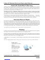
Shipping
By default, Intelix ships all North American orders via UPS on Intelix’s account. A $5 handling charge will be applied to
orders shipped via non-UPS carriers. Please contact the factory for all shipping estimates.
By default, Intelix ships all international orders via UPS on Intelix’s account. A $25 handling charge will be applied to
orders shipped via non-UPS carriers. A $10 handling charge will be applied to orders shipped via UPS on an account other
than Intelix’s. Please contact the factory for all shipping estimates.
A rush shipment fee of $50.00 applies to customer shipments requiring delivery faster than standard quoted delivery
schedule.
Note: Intelix Shipping Statement subject to change. Please contact the factory for the most up-to-date information.

Intelix VC Series Mic/Line Mixer User Manual
intelix 3
Table of Contents
Warranty............................................................................................................... 2
Introduction........................................................................................................... 6
1.0 Introduction............................................................................................................... 6
1.1 Safety Instructions...................................................................................................... 6
1.2 Maintenance Guidelines.............................................................................................. 6
1.3 Quick Start for the VC Series Mixer........................................................................... 7
1.3.1 Unpack and connect.................................................................................... 7
1.3.2 Power and setup......................................................................................... 7
1.3.3 Fine tuning................................................................................................... 7
1.3.4 Optional: special features activation............................................................. 7
Panel Descriptions................................................................................................. 8
2.0 Panel Descriptions...................................................................................................... 8
Installation and Operation.................................................................................... 10
3.0 Installation and Operation.......................................................................................... 10
3.1 Unpack and Connect.................................................................................................. 10
3.2 Recommended Input Wiring Methods........................................................................ 11
3.3 Channel 4 (on 4001 models) or 8 (on 8001 models)................................................... 12
3.4 Connect Ouput........................................................................................................... 12
3.5 Power Up................................................................................................................... 12
3.5.1 Connect the mixer power supply.................................................................. 12
3.5.2 Power up the mixer...................................................................................... 12
Gain Structure....................................................................................................... 13
4.0 Gain Structure............................................................................................................ 13
4.1 Gain Structure Illustration.......................................................................................... 14
4.2 Gain Setup on Standard VC Models........................................................................... 15
4.3 Gain Setup on Enhanced VCX Models....................................................................... 15
Mixer Fine Tuning................................................................................................. 16
5.0 Mixer Fine Tuning...................................................................................................... 16
5.1 Fine Tuning on both VC and VCX Models................................................................. 16
5.1.1 Low cut switch............................................................................................ 16
5.1.2 Phantom power switch................................................................................ 16
5.2 Additional Fine Tuning Options for VCX Models....................................................... 16
5.2.1 Aphex Aural Exciter..................................................................................... 16
5.2.2 Output limit switch...................................................................................... 16
5.2.3 Select bar graph readout.............................................................................. 17
5.2.4 The ground lift jumper................................................................................. 17
5.2.5 Rack the mixer............................................................................................. 17

Intelix VC Series Mic/Line Mixer User Manual
intelix
4
Special Features Activation................................................................................ 18
6.0 Special Features Activation...................................................................................... 18
External Control................................................................................................. 19
7.0 External Control...................................................................................................... 19
7.1 The Connectors....................................................................................................... 19
7.2 Mixer Expansion through Linking............................................................................ 20
7.3 DC Control.............................................................................................................. 21
7.3.1 Remote volume control............................................................................. 21
7.3.2 Connecting a remote volume control......................................................... 21
7.3.3 Remote mute control................................................................................. 21
7.3.3.1 Wiring an external mute switch................................................... 21
7.3.3.2 Wiring an external combination mute switch and volume control 22
7.4 Ducking................................................................................................................... 22
7.4.1 Setting Channel Duck Details.................................................................... 23
7.4.1.1 Duck trigger channel selection.................................................... 23
7.4.1.2 Ducked and no duck channel selection........................................ 24
7.4.2 Adjusting Duck Circuitry........................................................................... 24
7.4.2.1 Ducking amount......................................................................... 25
7.4.2.2 Duck release time....................................................................... 25
7.4.2.3 Group muting............................................................................. 25
7.4.3 Other Ducking Techniques........................................................................ 26
7.4.3.1 Remote (manual) ducking........................................................... 26
7.4.3.2 Linked ducking........................................................................... 26
Audio Inserting and Patching............................................................................. 27
8.0 Audio Inserting and Patching................................................................................... 27
8.1 Tapping the Direct Output....................................................................................... 27
8.2 Master Output Insert Patching................................................................................. 28
8.3 Balanced Line Link Input......................................................................................... 28
The 25EXT Card................................................................................................ 30
9.0 The 25EXT Card..................................................................................................... 30
9.1 Installing the 25EXT................................................................................................ 30
9.2 Remote Control with the 25EXT............................................................................. 31
9.2.1 Connecting a remote volume control....................................................... 31
9.3 Individual Channel Patching..................................................................................... 32
9.3.1 Patching instructions................................................................................. 32
9.3.2 Direct outs................................................................................................ 32
9.3.3 DC control and patching functions combined............................................ 32
Mixer Power Connections................................................................................... 33
10.0 Mixer Power Connections....................................................................................... 33
10.1 AC Power Connection............................................................................................ 33

Intelix VC Series Mic/Line Mixer User Manual
intelix 5
Troubleshooting Tips............................................................................................. 34
Technical Specifications........................................................................................ 36
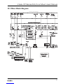
Mixer Block Diagram........................................................................................... 37
Glossary................................................................................................................. 38

Intelix VC Series Mic/Line Mixer User Manual
intelix
6
1.0 Introduction
This manual describes the components and operation of the Intelix VC Series
line of mic/line mixers. As with all Intelix products, the VC Series ensures the
highest quality audio signal production and control through easy-to-use fea-
tures.
Read all directions carefully before use.
The VC Series system includes a variety of electrical equipment; all precautions usually taken
with electrical equipment must be abided by. Specifically:
- Grounding: verify both the VC Series mixer and the devices connected to it are
properly grounded.
- Power Supply: use only the power supply provided by the manufacturer or one that
meets the manufacturer’s specifications.
- Cords and Cables: route all cords and cables so that they will not be trip hazards or
subject to damage (from being run over or pinched) which could cause them to be-
come shock hazards. Pay particular attention to cords at plugs, convenience recep-
tacles, and the point where they enter the mixer.
- Fire: if the mixer or other electrical equipment catches fire, extinguish the fire using
a carbon dioxide (CO2) extinguisher or any extinguisher rated for electrical fires.
Never use a water extinguisher.
1.1 Safety Instructions
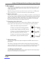
Electronic devices operate best in clean, well-ventilated environments. The VC Series mixer
contains many electronic components in a compact arrangement, thereby generating more
heat than the average electronic device. It should be located where it will be well-ventilated
and far from other heat-generating equipment, such as amplifiers.
The main ventilation ports are in the sides of the chassis. To operate properly, they must be
kept clear of other components (cables, etc.). When several VC Series mixers are located
together, the amount of heat generated may be difficult to dissipate if the units are stacked
directly on each other.
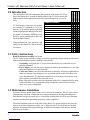
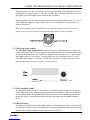
1.2 Maintenance Guidelines
VC Series mixers come in two 4 or 8-chan-
nel versions: VC (standard) or VCX (en-
hanced). VCX models include individual
channel signal present and clip LEDs, mas-
ter output VU metering, APHEX® Aural
Exciters, and an insert patch or direct out
for all channels.Feature
Congratulations on your purchase, and
enjoy your new Intelix VC Series mic/line
level mixer.
8001VCX
4001VCX
4 Channels
8 Channels
Remote Volume/Mute Control
Low Cut Filter
Stereo Line Level Input
+15V Phantom Power
Manual Volume Ducking
Priority Autoducking
Input Clip Indicator
Signal Preset LED’s
LED Bargraph Meter
APHEXTM Aural Exciter
Compressor/Limiter
4-Channel Insert Patching
8001VC
4001VC
Feature Chart

Intelix VC Series Mic/Line Mixer User Manual
intelix 7
Ensure adequate ventilation is provided on the sides, ambient air temperature does not
exceed 72 degrees F, and an open rack space is left above and below the units.
To minimize hum in the system, avoid placing cables near EMF-producing devices such as
electrical motors, fluorescent lights, AC power lines, and SCR dimmers.
Keep the mixer and other equipment clean and free of dust by occasionally wiping with a soft,
damp cloth.
Protect the mixer from electrical damage by disconnecting it from the power source whenever
it will be unused for a week or longer.
1. Check mixer for shipping damage.
2. Turn both mixer and amplifier volume controls to zero.
3. Connect inputs and set the input pad switch for each channel to the appropriate level (either
mic or line). Set all unused channels to line level.
4. Connect output and set the output pad switch at the appropriate (either mic or line) level.
1.3 Quick Start for the VC Series Mixer
1. Connect mixer’s AC power supply.
2. Power up mixer and amplifier.
3. Adjust the input volume for each channel by performing audio level tests. If necessary,
adjust the gain for individual channel(s).
4. Adjust the amplifier’s volume controls and master output volume.
5. Adjust individual channel volume knobs to achieve the desired mix.
Attach the DC control points and audio bus connections to the 25-pin connector on the rear
panel of the mixer. This will serve as an insert patch and allow linking, as well as enable
remote volume control, mute control, and duck control.
1.3.1 Unpack and connect
1.3.2 Power and set up
1.3.3 Fine tuning
1. In the event of excess bass, set the low cut filter switch to on.
2. If condenser mics are not otherwise powered, set the phantom power switch to on.
3. For VCX models only, increase the intelligibility of the signal by setting the Aphex® Aural
Exciter switch to on. In the event of excessive output level, set the limiter switch to on.
1.3.4 Optional: special features activation

Intelix VC Series Mic/Line Mixer User Manual
intelix
8
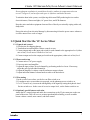
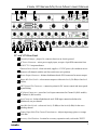
2.0 Panel Descriptions
2 3 8 9
B
A C
D
E F G H I J
VC and VCX Front Panel
Signal Present LED (on VCX models exclusively) - if lit (green), indicates at least a -10
dB input signal.
Channel Volume Knob (four on 4001 models, eight on 8001 models) - controls volume on
the input channel.
Low Cut Switch - eliminates low frequency noise, such as rumbling.
Signal Clip LED (on VCX models exclusively) - if lit (red), indicates a +18 dB or greater
input signal which may cause signal distortion.
Aphex® Aural Exciter Switch (on VCX models exclusively) - improves the quality of the
ouput signal by adding supplementary harmonic information to it.
Output Limiter Switch (on VCX models exclusively) - eliminates clipping distortion of the
output by controlling its dynamic range.
LED Bar Graph Output Meter (on VCX models exclusively) - displays output signal
levels in decibels, ranging from -18 (green) to +12 (red) dB.
Master Output Volume Knob - controls the mixer’s overall output signal level.
Power Switch Button - “in” position powers unit; “out” position powers down unit.
1
2
3
4
5
6
7
8
9

Intelix VC Series Mic/Line Mixer User Manual
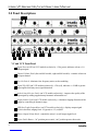
intelix 9
21 43 5 6 7 8 9
B
A C
D
E F G H I JK
VC and VCX Rear Panel
Ground Lift Jumper - jumper J4; connects chassis to an electric ground.
AC Power Connector - mixer power supply input; accepts a 4-pin DIN connection from
an 18VCT 1.5 amp transformer.
Phantom Power Switch - when activated, supplies +15 VDC power (for condensor micro-
phones) to all channels with the mic/line switch set to mic position.
Master Output Connector - balanced/unblanaced male XLR connector for master output.
Master Mic/Line Switch - selects master output as either mic level (-50 dBu) or line level
(0 dBu).
DB25 Control Pin Connector - connection points for DC remote control and insert patch-
ing and linking.
RCA Input Connectors - stereo line level input connections for Channel 8 (8001 models)
or Channel 4 (4001 models).
Input Connector - balanced/unbalanced male XLR input connection (balanced or
unbalanced); one per channel.
Input Mic/Line Switch - selects mic level (-50 dBu) or line level (0 dBu) for the corre-
sponding channel.
Channel Input Gain/Trim Control Potentiometer - Adjusts input stage gain over a range
of 40 dBu.
Accessory Card Position - location for accessory expansion cards, such as the 25EXT.
J
K
I
H
G
F
E
D
C
B
A

Intelix VC Series Mic/Line Mixer User Manual
intelix
10
Following these steps will ensure the installation and operation of your VC Series mic/line
mixer will be quick and effective.
3.0 Installation and Operation
First, remove the mixer from its box, inspecting the unit for shipping damage. If there is
obvious physical damage, contact Intelix immediately before proceeding with the installation.
Next, set all volume control knobs on the mixer to zero. Also, set all amplifier volume con-
trols to zero.
You are now ready to connect the physical inputs into the VC Series mixer (up to four inputs
on 4001 models and eight inputs on 8001 models). Insert the XLR input connectors into the
desired XLR input connector on the rear panel.
Set the XLR input pad microphone/line switch to the appropriate position: “in” for line input
and “out” for mic input. Note that the input from some microphones is actually closer to line
level (-20 dB); for such microphones, the switch should be set to the line position.
Note: Set the XLR input pad microphone/line switch for all unused channels to line level.
3.1 Unpack and Connect

Intelix VC Series Mic/Line Mixer User Manual
intelix 11
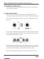
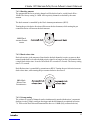
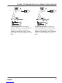
The following are the recommended
methods for connecting sources to the
Intelix VC Series mixer. The mixer input is
always balanced. From the following
drawings, choose the wiring method for your
input device (either balanced or unbalanced).
Balanced Source to Balanced Input
Shown is the normal wiring method for a
balanced source device. It has +6 dB gain
and excellent ground current and noise
rejection.
Balanced Source to Balanced Input
If the method above does not work in your
application, use the wiring shown. This
method solves certain ground loop
problems, having +6 dB gain and good noise
and ground loop rejection.
Unbalanced Source to Balanced Input
For an unbalanced source device, the draw-
ing shows the best wiring method. This
wiring provides a slight (+6 dB) boost, as
well as moderate noise and ground loop
rejection.
Unbalanced Source to Balanced Input
For an unbalanced source device, the draw-
ing shows an alternative wiring method.
Because the grounding of the minus input is
not to the mixer ground, this method does
not provide the +6 dB boost. Ground
current and noise rejection is good.
3.2 Recommended Input Wiring Methods
XLR
XLR
XLR
XLR

Intelix VC Series Mic/Line Mixer User Manual
intelix
12
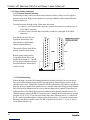
This channel accepts two types of inputs. Two inputs may be connected to the channel at the
same time, but only one at a time may be mixed.
The position of the channel’s XLR Input Pad Microphone/Line Switch determines which
input is mixed into the output; in the “mic” position, it uses the input connected to the XLR
Input Jack and in the “line” position, it uses the input connected to the RCA Jacks.
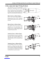
3.3 Channel 4 (on 4001 models) or 8 (on 8001 models)
Note: This channel accepts stereo inputs via the RCA
jacks. The channel’s output to the mixer is the mono
sum of the “R” and “L” RCA jack inputs.
The XLR jack for this channel accepts only mic level
inputs.
A connection should be made between the Master Output XLR Jack and an input jack of the
amplifier or other downstream equipment.
Press Output Pad Microphone/Line Switch to appropriate position: “in” for line-level output
(0 dBu) or “out” for mic-level (-50 dBu) output.
3.4 Connect Output
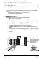
3.5 Power Up
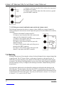
3.5.1 Connect the mixer power supply
Connect the mixer’s power supply to the AC power
jack on the rear of the unit, then connect the power
supply to a standard AC outlet.
3.5.2 Power up the mixer
1) Press the Power Switch to the “in” position (the
power indicator LED will light if mixer is powered).
2) Set the Master Output Volume Knob to “7”.
3) Power up the external amplifier.

Intelix VC Series Mic/Line Mixer User Manual
intelix 13
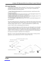
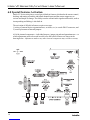
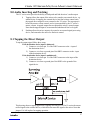
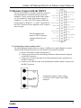
4.0 Gain Structure
To obtain the best performance from your Intelix VC Series mic/line mixer, you should first
understand the basic gain structure of the unit. There are four stages of gain adjustment
(labelled #1 through #4 in the drawing below):
1) channel input gain/trim control: this rear panel potentiometer controls the gain of the
microphone preamplifier.
2) channel volume knob: this front panel potentiometer controls (through the channel VCA)
the amount of channel that is fed to the mixer’s summing bus.
3) master volume control: this front panel potentiometer controls (through the master VCA)
the amplification of the summing bus to the output connector.
4) external amplifier volume control (not part of the mixer): sets the final listening level of
the loudspeakers.
The goal of setting up the mixer’s gain structure is to adjust these four controls for the desired
volume, while maintaining the best possible signal-to-noise ratio (S/N) through the mixer. This
is done by setting controls 2 and 3 at “7” where S/N and headroom are optimized, using
controls 1 and 4 to achieve maximum gain before distortion.
In order to maintain the highest level of S/N in the mixer, the audio signals are never brought
through the front panel controls of the Intelix mixer. Instead, each front panel pot controls a
Voltage Controlled Attenuator (VCA), which controls the associated amplification stage. The
channel VCAs do not control an amplifier, but are attenuation only devices which determine
the amount of each channel’s contribution to the summing bus.
Note: The VC and VCX models differ slightly in their setup procedures. Use the procedure
appropriate to your model (Section 4.2 for VC; Section 4.3 for VCX).

Intelix VC Series Mic/Line Mixer User Manual
intelix
14
MIC/LINE
INPUT
-70/-50
-10/+10 Db
MIC/LINE
OUTPUT
+4/-50 Db
Mic/Line
Switch
Line/Mic
Switch
PAD
PAD
40 dB
+4 dB +4 dB +4 dB
Limiter on
20 dB headroom
+24 dB
-20 dB
-30 dB
-70 dB -80 dB -80 dB
-50 dB
+40 dB
+24 dB +24 dB
High
Pass
Summing Bus
150 Hz
+
-G +G
Limiter Control
BAR GRAPH
APHEX EXCITER
_
Balanced
Line
Input
Rear Panel
DB-25 connector
Insert Patch
Nominal 0 dB
Single ended
J1
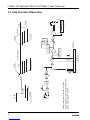
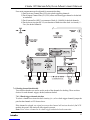
This drawing shows the flow of audio
signal through a single channel and demon-
strates a typical gain structure.
4.1 Gain Structure Illustration

Intelix VC Series Mic/Line Mixer User Manual
intelix 15
4.2 Gain Setup on Standard VC Models
Preliminary steps:
1. Ensure the audio sources are connected to the channel inputs on the VC Series
mixer.
2. Ensure the VC Series mixer’s output is connected to an external amplifier.
3. Set the input mic/line switches for the output channel and each input channel.
4. If condensor microphones are in use, enable the phantom power switch.
5. Set the front panel master volume knob to 7.
6. Set the front panel volume knob for the channel being setup to 7.
7. Set the external amplifier volumes to the desired acoustic levels.
8. If the channel has audible distortion at the above settings, reduce channel gain
with the input gain/trim control until the distortion is eliminated. Do not reduce
the front panel controls.
4.3 Gain Setup on Enhanced VCX Models
Preliminary steps:
1. Ensure the audio sources are connected to the channel inputs on the VC Series
mixer.
2. Ensure the VC Series mixer’s output is connected to an external amplifier.
3. Set the input mic/line switches for the output channel and each input channel.
4. If condensor microphones are in use, enable the phantom power switch.
5. Set the front panel master volume knob to 0.
For each channel, please follow these additional steps:
1. Set the channel volume knob to 0.
2. While driving the channel input at its normal level, adjust the input gain/trim
control clockwise until the peak (red) LED for the channel illuminates. Then,
rotate the input gain/trim control counterclockwise until the red LED goes out
or just flickers during peaks. Note that the signal present (green) LED will stay
lit during this procedure.
3. Set the master output volume knob to 7.
4. Turn the channel volume knob to 7.
5. Adjust the front panel channel control knobs to the desired level, as indicated
on the bar graph (the bar graph should be just into the yellow range). The bar
graph monitors the overall output; however, if each channel is adjusted indi-
vidually, the graph will reflect only that channel. Typically, the knob should be
set between 5 and 8.
6. Adjust the external amplifier volume to the desired acoustic level.
7. There is no need to adjust the master output volume and amplifier settings for
each subsequent channel. Do, however, adjust the rear panel input gain/trim
control and front panel channel control knob as needed.

Intelix VC Series Mic/Line Mixer User Manual
intelix
16
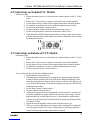
5.0 Mixer Fine Tuning
To remove excessive bass response from an
individual channel, press that channel’s low
cut switch.
The low cut feature helps eliminate low
frequency noise (signals of 150 Hz or lower;
e.g., ventilation rumble). This feature is
primarily used with mic-level inputs and is
particularly effective with hand-held micro-
phones.
If a condenser microphone is not independently powered,
press the phantom power switch to the on position. This
will cause the mixer to power condenser mics through
the mic cable. When the phantom power switch is in the
on position, all channels whose mic/line switches are in
the mic position receive phantom power (+15 VDC).
5.1 Fine Tuning on both VC and VCX Models
5.1.2 Phantom power switch
5.1.1 Low cut switch
5.2 Additional Fine Tuning Options for VCX Models
This feature enhances signal intelligibility by adding supplementary
harmonic information. It is especially effective at clarifying speech.
To engage the Aural Exciter, press the Aphex® Exciter switch to
the on position.
5.2.1 Aphex® Aural Exciter
The Output Limiter is a safety feature which protects the entire audio system from excessive
volume levels. It ensures the signal leaving the mixer does not exceed the system’s safe dy-
namic range. The factory setting is 0 dBu, but the threshold is variable from -20 dBu to +20
dBu and is set by adjusting a potentiometer inside the mixer chassis.
5.2.2 Output limit switch

Intelix VC Series Mic/Line Mixer User Manual
intelix 17
If during ordinary use one or more inputs occasionally exceed the maximum input levels set
up during the set up procedure (i.e., the red (+12 dB) LED on the bar graph meter occasion-
ally lights), press the Output Limiter Switch to the on position.
If during ordinary use one or more inputs continually exceed the maximum level (i.e., the red
LED continually lights), the input volume must be reset; return to the set up procedure as
defined in Section 3.
Note: If the amplifier/speaker combination is such that the speakers can be overdriven to
failure, always operate the mixer with the Output Limit Switch in the on position.
The LED Bar Graph Output Meter may be set to register either the peak or average level
of the output audio signal. To do so requires opening the chassis. The locations of the jumpers
for this are shown in section 6.0. The factory setting is to the average level; i.e., the Average
Bar Graph Jumper (J 3) is in place. To select peak level, move the jumper from J3 to the
Peak Bar Graph Jumper (J 2) instead. For the meter to operate, a jumper must be in one of
these two positions. Never place jumpers in both positions.
The ground lift jumper on all VC series mixers is a feature designed to help prevent ground
loops. When jumper J4 is present, it grounds the mixer to its chassis. If the mixer is installed
in a non-metal cabinet, the jumper is left in place. When the mixer is installed in a grounded
metal rack frame, use a needle-nose pliers to remove the jumper via the ground lift jumper
access.
Install the mixer in the rack or other cabinet where it will be when in use. The mixer should be
located away from heat sources, including other electronic components which generate a large
amount of heat, such as amplifiers. Verify the unit is well-secured.
5.2.3 Select bar graph readout
5.2.5 Rack the mixer
5.2.4 The ground lift jumper

Intelix VC Series Mic/Line Mixer User Manual
intelix
18
Intelix VC Series mixers have several special built-in features which make the remote control,
ducking, and muting of both the individual channel inputs and the master output easy to
activate and simple to change. The ability to make external audio signal modifications, such as
insert patching and linking, is also built-in.
The activation of all built-in features requires two steps:
1) wiring of external devices (potentiometers, switches, etc.) to a male DB 25 connector; and
2) correct placement of internal jumpers.
All of the internal components -- individual jumpers, jumper pin pads and potentiometers -- to
which adjustments need to be made in order to use the built-in features are shown in the
drawing below. Adjustments made to any other internal components may void the warranty.
6.0 Special Features Activation

Intelix VC Series Mic/Line Mixer User Manual
intelix 19
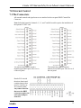
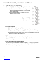
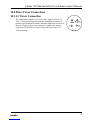
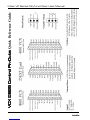
All external controls and signal sources are attached via the rear panel DB25 Control Pin
Connector.
Note: Individual control of channels 1, 3, 5, and 7 on 8001 models requires the installation of
the optional 25 EXT card.
7.1 The Connectors
7.0 External Control
The female DB25 pinout for 4001
models (upper DB25 port). The view is
of the rear panel.
The female DB25 pinout for 8001
models (lower DB25 port. The view is of
the rear panel.
Header P12 is inside
the mixer chassis and
contains jumpers that
must be correctly set
for external control.
Any remote function
that uses the DB25
connector requires the
removal of jumpers
from P12.

Intelix VC Series Mic/Line Mixer User Manual
intelix
20
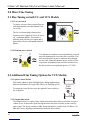
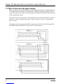
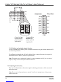
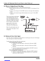
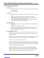
7.2 Mixer Expansion through Linking
Intelix VC mixers can be simply linked to provide a wider mixer bus. For example linking two
VC 8 channel mixers results in a 16 channel mixer. Although an indefinite number of mixers
can be linked in this way, Intelix recommends that you link no more than three mixers because
of the accumulation of noise.
To Link two mixers you must make a cable with a DB-25 on each end. The cable is wired so
that mixer 1’s pin 12 is connected to mixer 2’s pin 1 and mixer 1’s pin 24 is connected to
mixer 2’s pin 2.
Linking three mixers requires three DB-25 connectors wired as shown in the drawing below.
Note that the bottom unit (Mixer 3) has the sum of all three mixers.
Page is loading ...
Page is loading ...
Page is loading ...
Page is loading ...
Page is loading ...
Page is loading ...
Page is loading ...
Page is loading ...
Page is loading ...
Page is loading ...
Page is loading ...
Page is loading ...
Page is loading ...
Page is loading ...
Page is loading ...
Page is loading ...
Page is loading ...
Page is loading ...
Page is loading ...
Page is loading ...
-
 1
1
-
 2
2
-
 3
3
-
 4
4
-
 5
5
-
 6
6
-
 7
7
-
 8
8
-
 9
9
-
 10
10
-
 11
11
-
 12
12
-
 13
13
-
 14
14
-
 15
15
-
 16
16
-
 17
17
-
 18
18
-
 19
19
-
 20
20
-
 21
21
-
 22
22
-
 23
23
-
 24
24
-
 25
25
-
 26
26
-
 27
27
-
 28
28
-
 29
29
-
 30
30
-
 31
31
-
 32
32
-
 33
33
-
 34
34
-
 35
35
-
 36
36
-
 37
37
-
 38
38
-
 39
39
-
 40
40


Intelix 8001 VC User manual
- Category
- Musical Equipment
- Type
- User manual
Ask a question and I''ll find the answer in the document
Finding information in a document is now easier with AI
Related papers

Other documents
-
 DS18 V6HL PRO Owner's manual
-
Monacor CS-8 User manual
-
Rolls RM424 Four Zone Mixer User guide
-
Contacta STS-A31H User guide
-
DigitaLinx DL-HD2100 Owner's manual
-
-
-
-
DigitaLinx DL-DVI-S Operating instructions
-
