
Assembly and operating instructions
Bi-functional Electric Central Heating Flow Boiler
EKD.M3

Used product can’t be treated as general communal waste.
Disassembled appliance has to be delivered to the collection
point of electrical and electronic equipment for recycling.
Appropriate utilisation of used product prevents potential
negative environmental inuences that may occur as a result
of inappropriate handling of waste. In order to get more detailed
information about recycling this product you should contact the
local government unit, waste management service or the shop
where this product has been purchased.
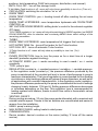
This appliance can be used by children aged from 3 years
and above and persons with reduced physical, sensory or
mental capabilities or lack of experience and knowledge if
they have been given supervision or instruction concerning
use of the appliance in a safe way and understand the
hazards involved. Children shall not play with the appliance.
Cleaning and user maintenance shall not be made by children
without supervision.

GB-088B_f. 3
Safety instructions
1. Read and strictly follow this installation and operating instructions to ensure a long
life and reliable boiler operation.
2. An efcient electrical installation which has been completed in accordance with the
binding norms.
3. Central heating system equipped with an appropriate expansion vessel completed
in accordance with binding norms of hydraulic installation.
4. Rinse the heating installation thoroughly before installing the boiler.
5. Do not install any barrier ttings (e.g. valves) on the outlet of the safety valve.
6. Boiler can only be installed on the at surface.
7. Boiler must not be installed in a humid place, in a place exposed to the danger of
explosion, or in which the temperature may drop below 0°C.
8. Boiler must be installed in such a place and in such a way in order not to ood the
room in case of the emergency water leak.
9. Boiler must be connected to water system and central heating system in accordance
with the manufacturer’s instructions. Failure to do so deprives the user from the
warranty rights and may cause device’s damage.
10. Installation of the device to the water supply must be compatible with all relevant
regulations in force.
11. Maximum pressure of the hot water storage must not exceed 0,3MPa. If system’s
pressure is higher than 0,6MPa, pressure reducing valve must be tted before
cylinder.
12. Water dripping from safety valves’ down pipe is a natural occurrence and it should
not be stopped, as its blockage may lead to the device’s failure.
13. It is forbidden to use the hot water storage if you suspect that safety valves may
be faulty.
14. The tank is equipped with a magnesium anode - an additional protection against
corrosion. The anode is an operating part, therefore, it is exposed to wear. The
condition of the magnesium anode should be controlled every 12 months, however,
it is due to be replaced with a new one every 18 months.
15. The boiler installation and electrical and hydraulic work must be performed by
a qualied professional installer in accordance with all instructions provided by the
manufacturer.
16. All installation work must be performed when the power and water supply are turned
off.
17. Electric installation should be equipped with residual current protective devices
and other solutions which will ensure disconnecting the heater from the source of
power (intervals between all their poles should not be less than 3mm).
18. Electronically controlled heater is a electrical surge sensitive device, therefore the
electrical installation must contain surge protection devices.
19. Do not drain the water from central heating system after the heating season.
20. Leave the controller in stand-by mode and do not cut off power supply between the
heating seasons. Proceeding otherwise may result in pump’s rotor blockage.

4
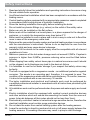
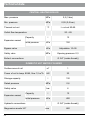
Boiler EKD is equipped with expansion vessels for central heating system and for DHW
(12 l capacity). The expansion vessel installed within the boiler for the central heating system
is sufcient only for the following capacities of the heating system at given temperatures
of the medium and at given pressure of central heating system.
Shall the capacity of the central heating installation be larger, an extra expansion vessel
must be installed (in accordance with binding norms).
If the boiler is to co-operate with under oor heating, it is necessary to install safety
armature.
Temperature of heating medium
(supply and return)
Capacity of central
heating system
Pressure in central
heating system
[°C] [l] [bar]
85/70 116
1,5
70/55 158
55/45 206
50/40 230
45/35 256
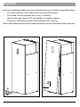
1. Install the boiler on the solid surface,
maintaining clearances from the
walls and the ceiling. Set the device
horizontally by adjusting device’s
regulation feet.
2. Connect the boiler to the central
heating system equipped with cut-off
valves. Description of the connectors
on page 5 and 10.
3. Fill the central heating system with
treated water or ERGOLID EKO liquid
it substantially extends the life of the
heating elements. When designing
heating installation heating medium
lling point must be provided. It is
recommend to place it as close the
boiler as possible.
min.100
min.100
200
min.50
580
1745
630
60
Installation
Installation notes
45 100 84 84 60 60 90 55
60

GB-088B_f. 5
4. Vent the central heating system.
5. Boiler’s installation to the water
system has to be carried out in
accordance with valid norms
safety valve must be installed on
cold water inlet.
6. Hot water outlet has to be
connected to the 3/4″connection
which is placed next to the
supplying connection.
7. If in the DHW system there is a
circuit, it has to be connected
to the 3/4″ connection which
is placed next to the hot water
connection, whereas the circuit
pump has to be connected to
PUMP.C clasp on the terminal
block.
8. Extend the pipes placed on
the back wall of the device,
responsible for safety valve’s
leak, and locate them as near the
oor drain as it’s possible. (Safe
and reliable operation, point 12.).
9. Connect the boiler to the electrical
system.
10. Fix internal (room) and external
temperature sensors and other
external appliance switch
cooperate acc. to ‚Connection of
external appliances & Controls’.
11. Once the above steps are
completed, you can start the
boiler and perform venting
procedure. (Conguration-Pump-
Venting)
12. Set the max. temperature of the
heating medium in the installation
(Conguration-Central heating-
Max power temperature).
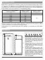
circulation
domestic hot water
cold water
return of heating medium
heating medium
supply
coil's supply- external heating
source
EKD EKD

6
1
1
NL
2
2
PNL
1
1
NL
PNL
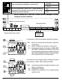
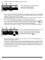
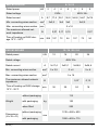
Connection to the three-phase electrical system.
PNL - points of neutral and protective conductor
connection
PF - points of phase conductors connection
[1] - temperature limiter (for boilers of 4kW, 6kW
and 8kW- additional conductors [2] have
to be removed and phase switches for the
electrical installation have to be changed
from single-phase to three-phase)
Connection to the single phase electrical system
(for boilers of 2kW. 4kW, 6kW and 8kW)
PNL - connection points of neutral, protective, and
phase conductors
[1] - temperature limiter
[2] - additional conductors (for single phase
system only)
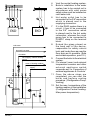
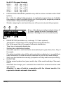
FN MA RT Tcyl Tos Tr
M.SUPPLY PUMP.C TWV PUMP
L N PE L N PE LB LA N L N PE PUMP
O G I
External devices’ inlets
Terminal block
→
→
A B
→
Boiler’s remote control
L N PE
Circulation
pump
→
NOTE: switch No. 1 and No. 2 must not be changed!- factory
settings must be retained.
Type of electrical installation- switch No.3 3 phase
1 phase
RS 485 terminator- switch No. 4 (see operating
manual for the module connected to the socket
of boiler’s remote control)
ON
OFF

GB-088B_f. 7
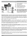
Temperature sensors - Temperature sensor’s wiring should be as short as possible, it
should not be led close to the power cord and it must not be twisted around other wires.
Install the outside temperature sensor (Tos) in the shade, on the north or northwestern
facade of the building, away from windows and ventilators. Install the room temperature
sensor (Tr) in a representative room in the building (such as a living room), away from
heaters, windows, doors, and communication lines.
Master appliance (entry MA) - In order to limit the power used, i.e. the boiler can
cooperate with other appliances such as an electric water heater. In order to do so, an
electrician should install in line an extra open contact to the MA entry (voltage free entry),
so that when a master appliance gets on, the contact opens, and the boiler switches
off- it results in heating blockage and pump’s standstill.
External adjustment of selected room temperature (inlet FN) - Closing FN contact
shifts boiler’s work to the mode of maintaining the temperature previously set in the
conguration menu (Conguration>FN entry).
Room thermostat (entry RT) - This optional entry is responsible for boiler’s control
depending on the room temperature. The entry has to be activated (Conguration>Room
temperature>Set outside room sensor)- when the voltage-free contact gets opened, the
boiler stops heating. Due to such adjustments, central heating system works with stable
parameters. (Conguration>CH circulation>Power temperature MAN).
Boiler’s remote control - In order to control boiler’s work remotely via online web page,
it is possible to connect the boiler to the Internet module (MI). Installation of MI module
is described in the module’s manual.
!
Tr
Tr
Tos
Tos
FN
FN
AB
FN MA RT Tcyl TosTr
MA
MA
RT
RT
Tcyl
Tcyl
FN - external adjustment of selected
room temperature
MA - master appliance
RT - alternative room thermostat
Tcyl - cylinder’s temperature sensor
Tos - outside temperature sensor
Tr - room temperature sensor
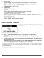
Under no circumstances should
any voltage be connected to
these terminals (FN, MA, RT, Tcyl,
Tos, Tr), as this will result in the
damage of boiler’s controller.
Connection of external appliances

8
Operation
Boilers are safe and reliable devices provided that the users follow the regulations below:
• The wear condition of the anode must be inspected annually.
• The anode must be replaced once every 18 months.
• Heat up the water above 70°C periodically for hygiene reasons.
• Failures or malfunctions notify to the manufacturer’s service.
Above activities are beyond of the scope of warranty service (should be done by the user).
1
2

GB-088B_f. 9
34
5
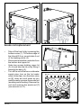
Anode rod replacement
• Take off the front lid by loosening the
bottom screw (1). Tilt bottom edge of
the lid and lift it up, so as to take it out
of the lashing points (2).
• Disconnect protective conductor from
the bottom and upper lid.
• Undo two screws holding upper lid
(3) (4) and take the lid out by tilting it
towards the back (5).
• Turn off the cut-off valve on cold water
supply pipe, turn on the hot water
valve (mixer tap), turn the drain valve
on [9], drain as much water as you
need to easily unscrew the anode rod
(avoiding room ooding). Remove the
cork and unscrew the anode rod [7]
(use wrench no 27).
7

10
1
7
8
2
6
5
4
3
10
9
11
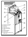
domestic hot water
cold water
coil's external heat source supply
power supply cable
circulation
heating medium supply
heating medium return
[1] - expansion vessel (DHW)
[2] - expansion vessel (CH)
[3] - pump (CH)
[4] - power board
[5] - safety valve CH 3bar
[6] - safety valve DHW 6bar
[7] - anode
[8] - electrical connection
[9] - drain valve DHW
[10] - drain valve CH
[11] - pipes conducting leakage from the
safety valves

GB-088B_f. 11
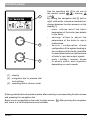
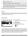
Control panel
2
3
9:37 THU 14.04.2020
9:37 THU 14.04.2020
24.2
24.2
°
°
5.1°
5.1°
60°
60°
1
Use the operating dial [3] to set one of
the modes: winter + / summer
/ off .
By turning the navigation dial [2] (left or
right), with winter or summer mode active,
change between function screens on the
display [1].
- main: informs about the basic
parameters of the boiler (see details
in the table),
- settings: allows to adjust the
parameters of the boiler to user’s
preferences,
- service / conguration: allows
conguration of the system heating to
the conditions of the facility (available
for specialized services) and preview
of boiler’s input and output signals,
- party / holiday / manual: allows
to quickly switch work algorithm
depending on user’s needs.
[1] - display
[2] - navigation dial to preview dial
and settings
[3] - operating dial to choose mode
Entering individual functions takes place after selecting a corresponding function screen
and pressing the navigation dial.
Boiler’s error is signalled on the main function screen. After pressing the navigation
dial, there is a list of detected errors available.

12
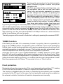
[1] - heat reception
[2] - executing of a heating program
[3] - temperature settings for the room
[4] - room temperature
[5] - outside temperature
[6] - storage temperature
Main screen
9:37 THU 14.04.2020
9:37 THU 14.04.2020
24.2
24.2
°
°
5.1°
5.1°
60°
60°
5
34
21 6
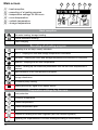
Heat reception
Hot water heating/ storage heating
Central installation heating
Buffer charging
Executing of a heating program
According to a set daily/ weekly schedule
PARTY - keeping the room and storage temperature comfortable
HOLIDAY - keeping the room and storage temperature economical or frost-proof
MANUAL - keeping the set room temperature
TURBO - heating up the maximum parameters until the set room temperature is
reached
Implementation of the frost protection program
Storage disinfection
Circulation pump venting
Heating blocked by signal from master device
Temperature settings for the room
Frost protection
Economic temperature
Comfort temperature
Comfort temperature plus
Comfort temperature minus
Request for heating from room regulator (with the internal regulator)
Signalling the implementation of buffer loading according to the schedule

GB-088B_f. 13
8:38 THU 14.04.2020
8:38 THU 14.04.2020
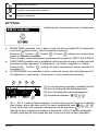
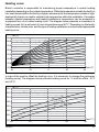
SETTINGS
SETTINGS
SETTINGS:
● ROOM TEMP (available only in basic mode and with activated I/S [Conguration
room temp > temp sensor > room temperature sensor]):
- Economic , Comfort - , Comfort , Comfort+ : setting room temperature
values in available schedules,
- Party, Holidays: select temperature parameters for programs: PARTY & HOLIDAYS
● TANK TEMP (available only in installation with domestic hot water cylinder and with
activated outside regulation. [Conguration > hot water >regulation > inside]):
- Economic , Comfort : setting hot water temperature values available in
schedules,
● CH PROGRAM (only available in basic mode and source with activated sensor Tr
[Conguration > room temp > temp sensor> room temperature sensor]):
CH Program No.1
CH Program No.1
END
END
1 6:00 - 9:15
2 15:20 - 22:15
2 15:20 - 22:15
1234
[1] - no. of time frame according to schedule (max 5)
[2] - time of starting the selected temperature
[3] - time of nishing the selected temperature
[4] - temperature selection: , , ,
Device’s error indication
Circulation pump operation indication
Heating on indication
Adjusting boiler ’s parameters to user ’s preferences
- No. 1...No. 8 > setting 8 daily programs. In each daily program there are 5 editable
time frames, which can have one of the room temperature sets ( ,,,)
In any other case, the economic temperature will be activated ( ).
Setting up daily programs procedure is described in Daily Schedule paragraph.
- Weekly: assigning for each week day one of the previously set daily programs.

14
- No 1...No8 - setting of 8daily programs, in each daily program there are available
5 time intervals in which cylinder buffer will be charging. Setting procedure of daily
programs is described in daily timetable.
- Weekly: assignment of one of the daily programs set for each day of the week
● DHW TANK PROGRAM (available only for storage tank systems):
- No. 1...No. 8 > setting 8 daily programs. In each daily program there are 5 editable
time frames, which can have one of the storage tank’s temperatures set ( ,)
In any other case, the economic temperature will be activated ( ).
Setting up daily programs procedure is described in Daily Schedule paragraph.
- Weekly: assigning for each day of the week one of the set daily programs or
a permanent program 9 (ECO).
Program No. 9 ECO is factory-set and it optimizes boiler’s operation while domestic
hot water is heated in order to achieve the best possible energy efciency class
in accordance with the terms of the ErP Directive. Individual (customized to user’s
needs) switching time and water temperature programming can decrease or
increase energy consumption.
DHW CYLINDER PROGRAM No.1
DHW CYLINDER PROGRAM No.1
END
END
1 6:20 - 8:00
2 18:30 - 23:00
2 18:30 - 23:00
1234
[1] - no. of time frame according to schedule (max 5)
[2] - time of starting the selected temperature
[3] - time of nishing the selected temperature
[4] - temperature selection: ,
BUFFER LOAD PROGRAM No.1
BUFFER LOAD PROGRAM No.1
Koniec
Koniec
1 6:00 - 8:00
2 18:30 - 23:00
2 18:30 - 23:00
123
1 - the number of the time interval (max.5)
2 - start time of buffer charging
3 - nish tine of buffer charging
● Buffer program (only available in buffer’s mode).

GB-088B_f. 15
● CIRCULATION PROGRAM (available only with the active circulation within DHW
system):
- No. 1...No. 8 > setting 8 daily programs. In each daily program there are 5 editable
time frames, in which circulation pump is on. Setting up daily programs procedure
is described in Daily schedule paragraph.
- Weekly: assigning for each week day one of the previously set daily programs.
No 9 ECO Program Schedule
00:00 - 10.00 Tcyl = 40°C
10:01 - 11.00 Tcyl = 64°C
11:01 - 20.00 Tcyl = 40°C
20:01 - 21:35 Tcyl = 64°C
21:36 - 23:59 Tcyl = 40°C
[1] - no. of time frame according to schedule (max 5)
[2] - time of starting the work of circulation pump
[3] - time of nishing the work of circulation pump
CIRCULATION PROGRAM No.1
CIRCULATION PROGRAM No.1
END
END
1 6:00 - 8:00
2 18:30 - 23:00
2 18:30 - 23:00
123
● DISINFECTION (available only in storage 1 2 3 tank systems):
- Temperature: temperature of the storage tank during disinfection,
- Day of the week: day of the week of automatic disinfection,
- Time: time of automatic disinfection,
- Working time: disinfection duration,
- Automatic operation: start disinfection automatically at a given time (Hour, Day of
the week),
- Circulation (available only with the active circulation switched on): a possibility to
select disinfection of either the whole installation or just the hot water storage.
- Start now: start disinfection manually (irrespective of a day and time set previously).
● DATE/ TIME:
- Setting current system time (year, month, day of the month and day of the week,
hour).
- Automatic time change: yes > automatic time switch from summer to winter mode
and reverse.
Attention: in case of boiler’s cooperation with the Internet module, it is
required to disable automatic time switch.

16
8:38 THU 14.04.2020
8:38 THU 14.04.2020
PARTY/HOLIDAY/MANUAL
PARTY/HOLIDAY/MANUAL
PARTY / HOLIDAY / MANUAL
Fast changing of the workflow algorithm according
to needs.
● INTERFACE:
- Brightness MIN: setting the brightness of the display in stand by mode
- Brightness MAX: setting the brightness of the display in working mode
- Sound: acoustic sound of the dial: YES/NO
- Dial sensitivity: 1- high / 4- low
● LANGUAGE:
- Select menu language.
● SYSTEM:
- MSK program: shows program version of boiler’s controller,
- PW program: shows panel’s software version,
- Max power: shows set boiler power,
- Auto change of time: yes -> automatic switching of system time from summer to
winter and vice versa,
- Reset: restarts the boiler,
- Factory settings: return to factory settings.
● PARTY: setting mode duration (from 1 to 24 hours or until cancelled)
● HOLIDAYS: setting mode duration (from 1 to 60 days or until cancelled).
● MANUAL: Set the room temperature by the system control - until cancelled.
● TURBO: turning on the place’s heating up with max parameters - until reaching the
set room temperature.
Attention: the option is available if the room temperature falls below the
current working temperature resulting from the schedule.
* If any of the above modes are ON, then after entering ‘Party / Holiday / Manual’ there is
a possibility to turn it off, and in case of setting the manual mode, it is also possible to change
the set temperature.
* Mode symbol is indicated on the main function screen.

GB-088B_f. 17
Preview of parameters:
preview of input and output signals of the boiler.
Conguration: adaptation of the boiler to the heating
system in the facility.
8:38 THU 14.04.2020
8:38 THU 14.04.2020
SERVICE/CONFIGURATION
SERVICE/CONFIGURATION
SERVICE / CONFIGURATION
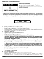
* (Changes in the conguration menu are possible after entering an access code. When prompted
for an access code, turn the navigation dial to the required code and conrm the code by pressing
the dial. If you want to retract from the code request screen, hold the navigation dial or wait until
automatic return to main function screen.)
Code : 987
● Buffer (available only in buffer’s mode)
- Buffer temp: temperature of the buffer charging factor,
- Load off-program: Yes- means consent to work outside the schedule with parameters
according to the needs of the heating modules.
● CENTRAL HEATING:
- Weather comp.: Choice of heating curve,
- Offset : offset of the heating curve.
- MAX boiler temp: The maximum temperature in CH installation.
Attention: adjustment of too high temperature parameters not compatible with
the type of building, central heating installation and building’s insulation may
lead to high exploitation costs.
- Set boiler temp.*: Temperature in CH installation when cooperating with constant
parameters and in emergency conditions.
- Regulation* / **: per curve / constant per curve > temperature in CH installation
is calculated on the basis of outside temperature and heating curve parameter.
Constant > temperature in CH installation is equivalent to Supply temperature MAN.
- Outside temp OFF: setting of selected temperature above which CH circuit will be
switched off
- Frost protection: frost protection of the building ON
* not available in buffer mode
** not available in source mode
● HOT WATER TANK:
- POWER TEMPERATURE: setting coil’s supply temperature.
- REGULATION: regulation of the temperature in the storage- INSIDE -> acc. to Tcyl/
OUTSIDE> acc. to outside thermostat (with OUTSIDE settings unavailable menu

18
positions: tank temperature, DHW tank program, disinfection, and manual)
- UNTIL CALL OFF - turn off the storage circuit.
*If Hot Water Tank function is off - menu will only show a possibility to turn it on (‘Turn on’).
● CIRCULATION: switching the circulation ‘on’ or ‘off’
● ROOM TEMP:
- ROOM TEMP CONTROL: yes -> heating turned off after reaching the set room
temperature.
- ROOM TEMP HYSTERESIS: room temperature hysteresis with ‘ROOM TEMP
CONTROL’ on.
- SET OUTSIDE ROOM SENSOR: shifting boiler’s control to the external regulator
(RT clasp)
*If OUTSIDE regulator is ‘on’- menu will only allow switching to INSIDE regulator (set INSIDE
ROOM SENSOR), after its selection and re-entering MENU items select settings of the
remaining parameters.
● TURBO:
- ROOM TEMP HYSTERESIS: room temperature fall triggers this function.
- HOT WATER TANK: No - turns off hot water for the Turbo function.
- UNTI CALL OFF - turns off automatic Turbo function.
*If Turbo function is off - menu will only show a possibility to turn it on (‘On’).
● PUMP:
- PUMPS PROTECTION: time to turn the pump on for a short time at a longer
standstill (protection against blocking).
- AUTOMATIC MODE: yes -> works according to user’s needs / no -> works
constantly.
- TYPE: pump’s type.
- REGULATION: constant p. -> constant pressure / variable p. -> variable pressure.
In the regulation mode (constant p.), the pressure difference produced by the
pump is maintained at the constant set level in terms of performance to pump’s
maximum characteristics. This type of regulation is recommended for oor heating
circulations or older heating systems with pipes of larger diameters, as well as for
all applications with constant characteristics. In the regulation mode (variable p.
the pressure difference produced by the pump is maintained at the level of settings
changing linearly between 1/2H and H. Setting pressure differences decreases
or increases depending on the ow. This regulation type is recommended for
heating systems with heaters, thanks to which ow noise in thermostatic valves
is reduced.
- VENTING: ON/OFF.
During venting procedure (10 min) the pump works alternately with a maximal and
minimal rotation speed. Thanks to this air bubbles are concentrated and easier to
remove from the installation.
- HMAX- pump’s raising height.
● MAX RATED POWER: setting heater’s rated power.
● COMMUNICATION:
- Device number: device’s number on the mains (setting ‘0’ turns off the mains
service).

GB-088B_f. 19
● INLET FN: selection of reaction to closing FN inlet: either setting economy
temperature or frost protection.
● PRESSURE CONTROL: no->switching the control off- pressure control should be
switched off only when boiler works in the open installation.
● Working mode: standard/source/buffer. Standard > boiler is the only device that
controls CH system. Source > boiler is only the heating source and CH circuit is
controlled by heating modules (working mode of the system described in operation
manual of the heating module). Buffer > boiler supervises buffer charging, buffer’s
discharge is done by heating modules (working mode of the system described in
operation manual of the heating module).
Exit any menu item by pressing ′End′ or by pressing and holding the navigation dial.
When not operated by the user, main function screen will appear after about 3 min.
Start-up
With the start-up of the boiler or after the restoration of the factory settings it is necessary
to select MENU’s language and boiler’s rated power. Boiler is ready to work properly
only after selection of these parameters.
Daily schedule:
CH PROGRAM No.1
CH PROGRAM No.1
END
END
1 6:00 - 9:15
2 15:20 - 22:15
2 15:20 - 22:15
23456
1 [1] - time period panel
[2] - no. of time frame according to schedule
(max 5)
[3] - time of starting
[4] - time of nishing
[5] - temperature selection
[6] - command (active when editing):
accept
delete
add
In daily schedule CH circuit and cylinder have dened starting time (3) and nishing
time (4) of maintaining selected temperature value (5) in the room (CH) or hot water
(cylinder). Outside dened time frames economy temperature will be maintained in the
room/cylinder. For circulation circuit within the schedule there is an adjustment of starting
time (3) and nishing time (4) of circulation pump’s operation. In buffer mode there is an
adjustment of starting time (3) and nishing time (4) of buffer’s charging.

20
Program CO Nr3
Program CO Nr3
Koniec
Koniec
1 0:00 - 23:59
Program CO Nr1
Program CO Nr1
1 6:00 - 9:15
1 6:00 - 9:15
2 15:20 - 22:15
2 15:20 - 22:15
To change the parameters for the daily schedule
select chosen program number and press
navigation dial.
The rst parameter ashes (starting time)- use
the navigation dial to set the new time frame
value (hour and minutes separately) by turning
the dial left/right and conrm it by pressing the
dial again. At the same time next screen starts to
ash allowing edition of next parameters. (nishing
time). Last editable position is a command. In order
to save changes select command ‘save’ and
press the dial to nish editing. To delete selected
time frame start editing chosen time frame and
by pressing the dial go to command position, select command ‘delete and press the
dial. To add new time frame, select last dened time frame and by pressing the dial go to
command position, select command ‘add’ and press the dial to add new time frame.
(edition of new time frames described above) If there are no dened time frames, then
after selecting ‘new’ the time frame 00:00am to 23:59pm will be set , which should be
edited in accordance with user’s needs.
The daily program will be saved to the boiler’s settings by pressing the command ‘END’.
TURBO function
If the facility is cold and if it is necessary to heat it up quickly, there is a possibility to
turn on the TURBO function. This function, when conditions to turn on the heating are
fullled, starts central heating installation with maximum parameters and continues until
required temperature is reached in a room. This function can start automatically when
room’s temperature falls down by the set room temperature hysteresis.
Automatic work is set in menu CONFIGURATION > TURBO. Selection of ‘Hot water
tank- NO’ will result in switching off hot water heating priority for the time of using Turbo
function. In menu Party/Holidays/Manual it is possible to turn on this function manually
(without hot water heating up priority), on condition that the room’s temperature is lower
than the programmed one. Sensor Tr is required to turn on Turbo function.
Frost protection
During stand-by and summer modes, if the room temperature drops below 7°C, heating
of CH circuit will be activated. Tr sensor is required to activate this function.
The function is disabled when the boiler is controlled by an external room controller
connected to the RT input. In this case, the frost protection mode must be enabled on
the external controller, the boiler will maintain temperature set manually.
Page is loading ...
Page is loading ...
Page is loading ...
Page is loading ...
-
 1
1
-
 2
2
-
 3
3
-
 4
4
-
 5
5
-
 6
6
-
 7
7
-
 8
8
-
 9
9
-
 10
10
-
 11
11
-
 12
12
-
 13
13
-
 14
14
-
 15
15
-
 16
16
-
 17
17
-
 18
18
-
 19
19
-
 20
20
-
 21
21
-
 22
22
-
 23
23
-
 24
24


Ask a question and I''ll find the answer in the document
Finding information in a document is now easier with AI
Related papers
Other documents
-
Tech Controllers EU-293v2 User manual
-
 TECH EU-i-2 Owner's manual
-
 Tech Controllers EU-i-3 User manual
-
 Tech Controllers EU-293 User manual
-
 TECH EU-i-1 CWU Owner's manual
-
 Tech Controllers EU-293v3 User manual
-
 Tech Controllers EU-T-4.1 Wired Two-State Room Regulator User manual
-
Tech Controllers EU-2801 User manual
-
Tech Controllers ST-2801 User manual
-
 TECH EU-292 v2 User manual


