ITW Food Equipment Group ML-052822 User manual

Category
Cookers
Type
User manual
ITW Food Equipment Group, LLC
3600 North Point Blvd.
Baltimore, MD 21222
RETAIN THIS MANUAL FOR FUTURE USE
FORM F-36951 (04-07)
INSTALLATION & OPERATION MANUAL FOR
Stockpot Range
MODELS
MLS
VSP100
ML-052822
VSP200
ML-052823
VSP200F
ML-769292
www.vulcanhart.com
MODELS
MLS
WSPR1
ML-760600
WSPR2
ML-760601
WSPR2F
ML-769292
www.wolfrange.com
V
SP100
WSPR2F
-
2 -
IMPORTANT FOR YOUR SAFETY
THIS MANUAL HAS BEEN PREPARED FOR PERSONNEL QUALIFIED TO
INSTALL GAS EQUIPMENT, WHO SHOULD PERFORM THE INITIAL FIELD
START-UP AND ADJUSTMENTS OF THE EQUIPMENT COVERED BY THIS
MANUAL.
POST IN A PROMINENT LOCATION THE INSTRUCTIONS TO BE FOLLOWED IN
THE EVENT THE SMELL OF GAS IS DETECTED. THIS INFORMATION CAN BE
OBTAINED FROM THE LOCAL GAS SUPPLIER.
IMPORTANT
IN THE EVENT A GAS ODOR IS DETECTED, SHUT
DOWN UNITS AT MAIN SHUTOFF VALVE AND
CONTACT THE LOCAL GAS COMPANY OR GAS
SUPPLIER FOR SERVICE.
FOR YOUR SAFETY
DO NOT STORE OR USE GASOLINE OR OTHER
FLAMMABLE VAPORS OR LIQUIDS IN THE VICINITY OF
THIS OR ANY OTHER APPLIANCE.
WARNING: IMPROPER INSTALLATION, ADJUSTMENT,
ALTERATION, SERVICE OR MAINTENANCE CAN
CAUSE PROPERTY DAMAGE, INJURY OR DEATH.
READ THE INSTALLATION, OPERATING AND
MAINTENANCE INSTRUCTIONS THOROUGHLY BEFORE
INSTALLING OR SERVICING THIS EQUIPMENT.
IN THE EVENT OF A POWER FAILURE, DO NOT
ATTEMPT TO OPERATE THIS DEVICE.
-
3 -
INSTALLATION, OPERATION AND CARE OF
STOCKPOT RANGE
GENERAL
Stockpot ranges are designed for commercial use only and feature fast, efficient gas
heat. Each burner is controlled by an adjustable gas valve. Heavy-duty, cast iron top
grate(s) are easily removed for cleaning when cool. A grease drawer is provided to collect
fat run-off; it opens to the front for inspection or drain-off.
Model Number of Burners BTU/hr Input Rating
VSP100, WSPR1 2 110,000
VSP200, WSPR2 4 220,000
VSP200F, WSPR2F 4 220,000
INSTALLATION
UNPACKING
Immediately after unpacking, check for possible shipping damage. If the stockpot is
found to be damaged, save the packaging material and contact the carrier within 15 days
of delivery.
Before installing, verify that the type of gas (natural or propane) and the clearance
dimensions (see below) agree with the specifications on the rating plate which is located
at the back of the stockpot.
LOCATION
The installation location must be kept free and clear of combustibles. Do not obstruct the
flow of combustion and ventilation air. DO NOT install the stockpot adjacent to open
burners or fryers.
Sufficient air should be allowed to enter the room to compensate for the amount of air
removed by any ventilating system and for combustion of the gas burners. Do not
obstruct the air flow into and around the appliance. Do not obstruct the flow of flue gases
through and above the stockpot top grate. Position the stockpot in its final location.
Check that there are sufficient clearances to service the stockpot and to make the
required gas supply connection(s). Provide 24" clearance at the front for cleaning,
maintenance, service and proper operation.
Minimum Clearance Combustible Construction Non-Combustible Construction
Rear 24” 4”
Sides 18” 0”
-
4 -
INSTALLATION CODES AND STANDARDS
The Stockpot Range must be installed in accordance with:
In the United States of America:
1. State and local codes.
2. National Fuel Gas Code, ANSI-Z223.1/NFPA #54 (latest edition). This shall include but
not be limited to: NFPA #54 Section 10.3.5.2 for Venting. Copies may be obtained
from The American Gas Association Accredited Standards Committee Z223, @ 400
N. Capital St. NW, Washington, DC 20001 or the Secretary Standards Council, NFPA,
1 Batterymarch Park Quincy, MA 02169-7471
NOTE: In the Commonwealth of Massachusetts
All gas appliances vented through a ventilation hood or exhaust system equipped with
a damper or with a power means of exhaust shall comply with 248 CMR.
3. NFPA Standard # 96 Vapor Removal from Cooking Equipment, latest edition, available
from the National Fire Protection Association, Batterymarch Park, Quincy, MA 02269.
In Canada:
1. Local codes.
2. CAN/CSA-B149.1 Natural Gas Installation (latest edition)
3. CAN/CSA-B149.2 Propane Installation Code (latest edition), available from the
Canadian Gas Association, 178 Rexdale Blvd., Etobicoke, Ontario, Canada M9W
1R3
GAS PRESSURE REGULATOR INSTALLATION
Gas regulator pressure is preset at 5” Water Column (W.C.) for natural gas, and 10” W.C.
for propane gas. Minor adjustments may be required based on site specific gas pressure.
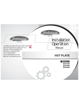
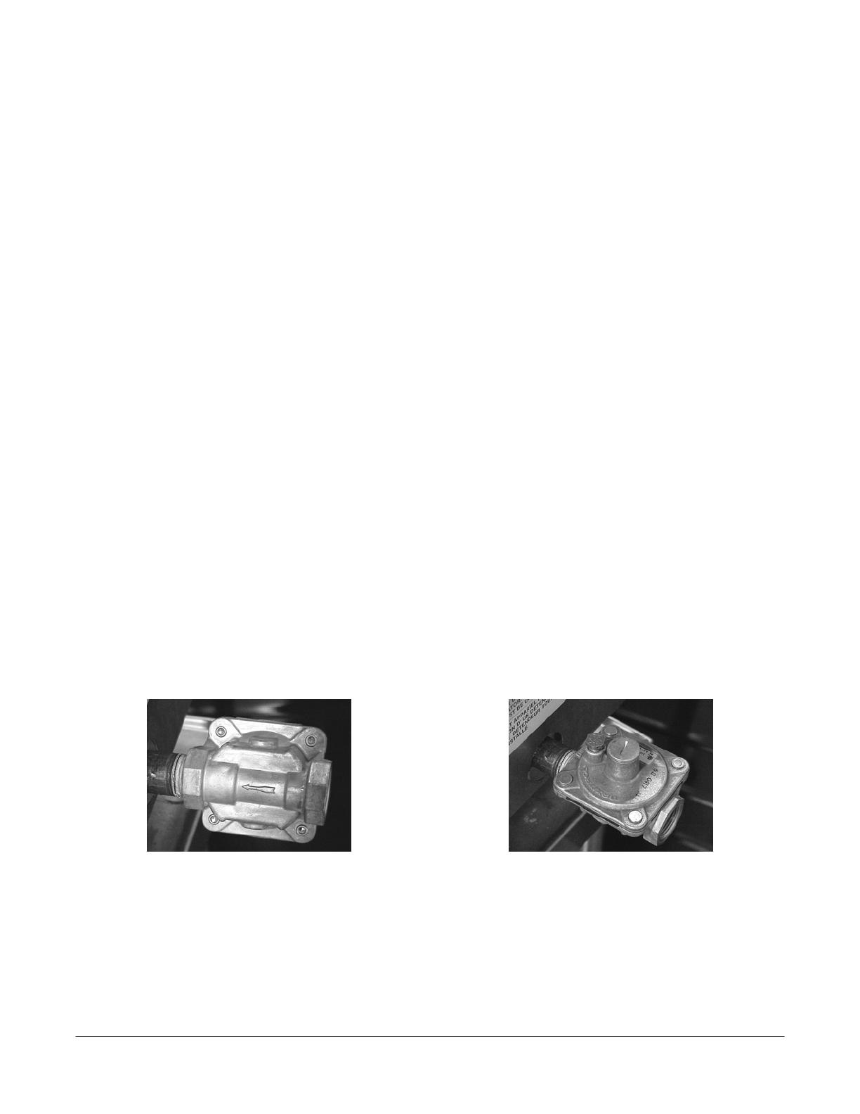
Install the regulator as close to the stockpot on the gas supply line as possible. Make
sure that the arrow on the underside of the regulator is oriented in the direction of gas
flow to the stockpot (Fig. 2) and the regulator is positioned with the vent plug and
adjustment screw upright (Fig. 3).
Fig. 2
Fig. 3
The minimum supply pressure (upstream of the regulator) should be 7-9” W.C. for natural
gas and 11-12” W.C. for propane gas. At no time should the hotplate be connected to
supply pressure greater than ½ psig (3.45 kPa) or 14” W.C.
-
5 -
LEVELING
The Stockpot Range is equipped with legs. Turn the feet at the bottom of the legs in or
out to level the Stockpot Range in the final installed location.
VENTILATION HOOD
The stockpot should be installed under a suitable ventilation hood. For safe operation and
proper ventilation, keep the space between the stockpot and vent hood free from any
obstructions.
GAS CONNECTION
The data plate on the lower right side of the charbroiler indicates the type of gas your unit
is equipped to burn. DO NOT connect to any other gas type.
CAUTION: All gas supply connections and any pipe joint compound must be
resistant to the action of propane.
Purge the supply line to clean out any dust, dirt, or any foreign matter before connecting
the line to the unit.
Codes require that a gas shut-off valve be installed in the gas line ahead of the
charbroiler. The gas supply line must be at least the equivalent of ¾” iron pipe. 72-inch
units should be connected to the gas supply on both the left and right sides to provide
adequate gas flow.
A pressure regulator is supplied and must be installed outside of the broiler when making
the gas supply connection. Standard orifices are set for 5"WC (Water Column) for
Natural Gas — 10"WC (Water Column) for Propane. Use the
1
/
8
” pipe tap on the burner
manifold for checking pressure. Make sure the gas piping is clean and free of
obstructions, dirt, and piping compound.
An adequate gas supply is necessary. Undersized or low pressure lines will restrict the
volume of gas required for satisfactory performance. A maximum supply pressure of 7"
W.C. for natural gas and 11" W.C. for propane gas is recommended. With all units
operating simultaneously, the manifold pressure on all units should not show any
appreciable drop.
When testing the gas supply piping system, if test pressures exceed ½ psig (3.45 kPa),
the charbroiler and its individual shutoff valve must be disconnected from the gas supply
piping system. When test pressures are ½ psig (3.45 kPa) or less, the charbroiler must
be isolated from the gas supply piping system by closing its individual manual shut-off
valve during any pressure testing of the system.
WARNING: PRIOR TO LIGHTING, CHECK ALL JOINTS IN THE GAS SUPPLY LINE FOR
LEAKS. USE SOAP AND WATER SOLUTION. DO NOT USE AN OPEN FLAME.
-
6 -
OPERATION
WARNING: THE STOCKPOT RANGE AND ITS PARTS ARE HOT. BE CAREFUL WHEN
OPERATING, CLEANING OR SERVICING THE STOCKPOT RANGE.
CONTROLS
The burner is in two sections, controlled by two heavy duty infinite control valves. The
center “Star” section (Fig. 2) is on separate burner with an input of 55,000 BTU/hr. It is
controlled by the right burner valve knob. The outer circle of the burner (Fig. 2) is the
other separate 55,000 BTU/hr input burner, controlled by the left burner valve knob.
These two separate burners provide heat flexibility. With one burner off and the second
burner set low, up to both burners full on, you can move from low simmer on up to
110,000 BTU/hr input.
Fig. 1
Fig 2.
LIGHTING INSTRUCTIONS
1. Turn all burner valves to OFF position and wait 5 minutes.
2. Turn gas shutoff valve ON.
3. Light standing pilot with a lit taper. Adjust pilot to ¼” high flame, if necessary, by
turning pilot valve adjusting screw (see Fig. 1) counterclockwise to increase or
clockwise to decrease flame.
4. Turn burner valve to ON position.
5. If pilot does not light, turn main gas supply OFF and repeat steps 1 through 4.
TO COMPLETELY SHUTDOWN THE BURNERS AND PILOT LIGHTS
For complete shutdown: Turn the main gas supply valve OFF.
INNER
BURNER
OUTER
BURNER
PILOT VALVE
SCREW
-
7 -
CLEANING
Top grate(s) may be immersed in strong commercial cleaning compound overnight. In the
morning, rinse with hot water to remove any residues of cleaning compound.
Stainless steel surfaces may be cleaned using damp cloth with mild detergent and water
solution.
Places where fat, grease, or food can accumulate must be cleaned regularly.
MAINTENANCE
WARNING: THE STOCKPOT RANGE AND ITS PARTS ARE HOT. USE CARE WHEN
OPERATING, CLEANING, OR SERVICING.
SERVICE
Contact your local Service Agency for any repairs or adjustments needed on this
equipment.
TROUBLESHOOTING
PROBLEM POSSIBLE CAUSES
Pilot Outage
1. Pilot flame too low
2. Restriction in pilot orifice
3. Restriction in pilot valve
Improper burner
combustion
Improper ventilation
Poor Ignition
1. Insufficient gas input
2. Poor air-gas adjustment
3. Restriction in pilot orifice
4. Restriction in main burner ignition port
5. Restriction in control valve
6. Restriction in gas orifice
  • Page 1 1
  • Page 2 2
  • Page 3 3
  • Page 4 4
  • Page 5 5
  • Page 6 6
  • Page 7 7

ITW Food Equipment Group ML-052822 User manual

Category
Cookers
Type
User manual

Ask a question and I''ll find the answer in the document

Finding information in a document is now easier with AI