Page is loading ...

Owner's Manual
42" HIGH PERFORMANCE
LAWNSWEEPER
Model No. 486.24211
\
\
CAUTION:
Before using this product, read
this manual and follow all Safety
Rules and
Operating Instructions.
IMPORTANT - READ THIS FIRST!!!
For Missing Parts or Assembly Questions
Please Call 217-728-8388
Mon.-Fri, 7 am - 5 pm CST.
FAX 217-728-2032 or e-mail info@agri-fab.com
Missing parts will be sent UPS in 24 hours directly to your home.
Sears, Roebuck and Co., Hoffman Estates, IL 60179 U.S.A.
www.sears.com/craftsman
PRINTED IN U.S.A.
• Safety
• Assembly
• Operation
• Maintenance
• Parts
FORM NO. 46821 (REV. 8/01)

SafetyRules ...................................................................... 2
Full Size Hardware Chart .................................................. 3
Carton Contents ................................................................ 4
SweeperAssembly Instructions ........................................ 5
HopperAssembty Instructions .......................................... 7
Know Your Sweeper ....................................................... 11
How To Use Your Sweeper ............................................. 11
Maintenan_eSchedule... ................................................ 12
Storage ........................................................................... 12
Service and.Adjustments .....,;...................................... ...13
Trouble_' , : , 13
. , o_;...,.:_...._,...............................................
Repair Pa_s Illustratton .................................................... 14
Repair PartsList ....._........................................................ 15
Parts Ordering/Service ..................................... Back Cover
LIMITED TWO YEAR WARRANTY ON CRAFTSMAN LAWNSWEEPER
For two years from the date of purchase, when this Lawnsweeper ismaintainecl _n_ iubricated accordingto the operating
and maintenance instructionsinthe owner's manual, Searswillrepairfree ofcharge anydefect in material orworkmanship.
This warranty does not cover repairs necessary because of operator abuse or negligence, including the failure to maintain
the equipment according to instructions contained in the owner's manual; and Lawnsweeper used for commercial or rental
purposes.
AVAILABLE' BY CONTACTING THE NEARES_AR. S:SERVtCE CENTER/DEPARTMENT
WARRANTY SERVICE IS
IN THE UNITED STATES.
This warranty applies only while this product is in the United States.
This warranty gives you specific legal rights, and you may also have other rights wh Chvary from state to state.
Sears, Roebuck and Co. D/817WA, Hoffman Estates, Chicago, 1L 60179 _,_ . :
Any power equipment can cause injury if operated improperly or if the uS'_i;'_oes'n0t understand how to operate
the equipment. Exercise caution at all times, when using power equipment.
1, Read the vehicle and sweeper owners manuals and 6. Vehicle braking and stability may be affected with the
know how to operate your vehicle and sweeper
before using this sweeper attachment. Always
instruct other users before they operate the sweeper.
2, Do not permit Childrento operate sweeper.
3. Do not pe:rmit aityone to ride on sweeper.
4. Never attach the hopper rope to any part of your
body or _[0thifig! Never hold onto the rope while
towing the sweeper! Attach the rope to the towing
vehicle ]Okeep it away from wheels and rotating
parts,
5. Operate the sweeper at reduced speed on rough
terrain, near ditches and on hillsides to prevent loss
of control.
attachment of this _sweeper. Do not fillsweeper to
maximum capacity without checking the capability of
the towing vehicle to safely pull and stop with the
sweeper attached. Stay off of steep slopes.
7. Stop and inspect vehicle and sweeper for damage
after strikingan object,Repair any damage before
continuing operation,. ,
8. Keep sweeper away from fire. Excessive heat can
damage the brushes and hopper bag and could
cause the bag and itscontents to burn.
9. Before storing the sweeper, always empty the hopper
bag to avoid spontaneous combustion.
10. Follow maintenance,a9d !ubricationinstructionsas
outlined in the mainter_anCe section'_f th:ismanual.
I& ook for this symbol to point out important safety precautions. It means--At'_en|i_ntt
Become alertll Your safety is involved.
The modeland serial numbers willbe found on a decal
attached to the lawnsweeper.
You shouldrecordboth the serial numberand the date of
purchase and keep in a safe place for future reference.
MODEL NUMBER: 486.24211
SERIAL NUMBER: • '_
DATE OF PURCHASE: .... ' ' '

,,..+--+-t
.,-----t
......,..,i-i
..-----t
_-i.---1
,------1
SHOWN FULL SIZE
.,,j , j
i
i 1
AA _BB
NOT SHOWN FULL SIZE
EE
tGG
_-") __HH
:IEF.
A
B
C
D
E
F
G
H
I
J
K
L
M
N
O
9
Q
QTY.
2
1
1
4
2
2
4
1
1
6
2
3
8
4
4
6
2
DESCRIPTION
Hex Bolt, 5/16-18 x 3" Lg.
Hex Bolt, 5/16-18 x 2-1/2" Lg.
Hex Bolt, 5/16-18 x 2-1/4" Lg.
Hex Bolt, 5/16-18 x 1-3/4" Lg.
Hex Bolt, 1/4-20 x 1-1/4" Lg.
Hex Bolt, 3/8-16 x 3/4" Lg.
Hex Bolt, 5/16-18 x 3/4" Lg.
Carriage Bolt, 3/8-16 x 1" Lg.
Carriage Bolt, 5/16-18 x 3/4" Lg.
Slotted Screw, #10-32 x 5/8" Lg.
Curved Head Bolt, 1/4-20 x 1" Lg.
Hex Lock Nut, 3/8"
Hex Lock Nut, 5/16"
Hex Nut (Plain), 5/16"
Hex Lock Nut, 1/4"
Hex Lock Nut, #10-32
Palnut, 3/8"
FIEF.
R
S
T
U
V
W
X
Y
Z
AA
BB
CC
DD
EE
FF
GG
HH
QTY.
1
1
2
6
1
1
1
2
2
1
2
4
2
1
1
1
1
DESCRIPTION
Flat Washer, 3/8"
Flat Washer, 5/16" Standard
Flat Washer, 5/16" (Small)
Lock Washer, 5/16"
Washer, Tooth Lock 5/16"
Cotter Pin, 1/8" x 3/4"
Hairpin Cotter, 1/8"
Hairpin Cotter, 3/32"
Clevis Pin, 1/4" x 1-1/2"
Spacer Bushing,
Hitch Spacer, 3/4"
Hopper Mount Clamp
Vinyl Cap
Grip
Knob, Plastic
Hitch Pin
Spring

CARTON CONTENTS (Loose Parts in Carton)
1..Sweeper Housing Assembly
2. Bag Arm Tube (2)
3. Hitch Tube, L.H. (Left Hand)
4. Hitch Bracket
5. Hitch Bracket (Straight)
6. Hitch Pin Bracket
7. Height Adjustment Strap
8. Height Adjustment Handle
9. Hitch Tube, R.H. (Right Hand)
10. Rope
11. Hopper Bag
t2. Windscreen
13. Upper Hopper Tube, R.H.
14. Upper Hopper Tube, L.H.
15. Lower Hopper Tube, R.H.
16, Lower Hopper Tube, L.H.
17. Hopper Bag Pivot Rod
18. Hopper Support Rod (2)
19. Bag Retaining Strap
20. Bag Frame Strap
12
20
1
CARTON CONTENTS
REMOVAL OF PARTS FROM CARTON
• Remove the sweeper, the looseparts and the hardware
package fromth_'carton_ Layout the parts and hard-
ware as shown on pages 3 and 4.
TOOLS REQUIRED FOR ASSEMBLY
(1)
(1)
(1)
(1)
(1)
(1)
(1)
(1)
Pliers
Screwdriver
Hammer _ =,
Adjustable,W.rench
9/16" Open End or Box End Wrench
7/16" Qpen.End or Box En_l,Wrench
1/2" Open End or Box EndWrench
3/8" Open End or Box End Wrench

ASSEMBLY OF SWEEPER
Note: Right hand (R.H.) and left hanoi (L.H.) are deter-
mined from the operators position while seated on the
tractor.
• Cut offthe plastictie holding the height adjustment tube
in place. See figure 1. _
• Assemble the R.H, and L.H. hitch tubes to thesweeper
housing using four 5/16" x 1-3/4" hex bolts, 5/16" lock
washers and 5/16" hex nuts. Do not tighten yet. See
figure 1.
5/16"x 1-314"
HITCH TUBE(LH.) _L_/
FIGURE 1
Place the spacer bushing intothe holein the height
adjustment strap. Place the strap withbushing between
the hitch tubes, aligned with the rear hole. Fasten the
hitch tubes together, with the strap and bushing be-
tween them, usingtwo 5/16" x 3" hex bolts, 5/16" flat
washers (smaller), 5/16" lock washers and 5/16" hex
lock nuts. Do not tighten yet. See figure 2.
5116"x 3"
HEX BOLT
5/16" HEX
LOCK NUT
• ',Assemble÷_ ihe Ilitch pin bmcket_, the spring and the
ii_3/8"flat washer ontothe hitch pin. Secure them onto
the hitchpin with a 1/8" x 3/4" cotter pin placed into
the middle hole in the hitchpin. Spread ends ofcotter
pin around hitch pin. See figure 3.
• Assemblethe hitch pin bracket to the straight hitch
bracket using a 3/8" x 1"carriage bolt and a 3/8" hex
lock nut. Align the brackets and tighten. See figure 3.
3/8" x 1"CARRIAGE BOLT--_<_.,_.q,...HITCH__
BRACKET
(STRAIGHT)
1/8" x 3/4" COTTER PIN-"_
3/8" FLATWASHER_"/_
./
SPRING
HITCHPIN
FIGURE 3
I
' N
_..._.. HITCHPI
"_,................_BRACKET_
_"_- 3/8" HEX LOCKNUT
•MIDDLE HOLE
If your tractor hitch has 10" to 13" ground clearance
use the instructions below to assemble the sweeper
hitch brackets, if your tractor hitch has less than 10"
ground clearance, go to page 6.
Place the bent hitch bracket on top of the hitch tubes
and place the straighthitchbracket with hitchpin under-
neath the hitch tubes. Fasten together using a 5/16" x
2-1/2" hex bolt (front), a 5/16" x 2-1/4" hex bolt (rear)
and two 5/16" hex lock nuts as shown in figure 4. The
bolts should straddle the front hitch tube bolt. Do not
tighten yet.
At this timetighten the four bolts fastening the hitch
tubes to the sweeper housing. Next, tighten the two
bolts fastening the hitch tubes together. Finally, tighten
the two bolts fastening the hitch brackets to the hitch
tubes.
• Assemble the two 3/4" spacers ontothe hitch pinand
secure the pin with the 1/8" hairpin cotter, See figure 4.
5116" x 2-112"
HEX BOLT
1/6" HAIRPIN "_
COTTER
HITCH
BRACKET .._,-1
314" SPACERS"
HITCH PIN
BRACKET
5/16" x 2-114"
HEX BOLT
5/16" J-IEXLOCK NUTS
FIGURE 2
FIGURE 4

Ifyourtractorhitchhas8"to 10"groundclearance,
usethe instructionsbelowto assemblethesweeper
hitchbrackets.Ifyourtractorhitchhasmorethan10"
groundclearance,referback topage5fortheassem-
blyofthesweeperhitchbrackets.
• Place the bent hitch bracket underneaththe hitch tubes
and place the straight •hitch bracket with hitch pin on top
of the hitch tubes. Fasten together using a 5/16" x 2-1/2"
hex bolt (front), a 5/16" x 2-1/4!!hex bolt (rear) and two
5/16" hex lock nuts as shown in figure 5. The bolts
should straddle the front hitch tube bolt, Do not tighten
yet.
• •
At this time tighten the four bolts fastening the hitch
tubes tothe sweeper housing.Next, tighten the two
boltsfastening the hitchtubes together. Finally,tighten
the twobolts fastening the hitchbracketsto the hitch
tubes.
• Assemble the two 3/4" spacers onto the hitch pin and
secure the pin with the 1/8" hairpin cotter. See fiqure 5.
e
Assemble the height adjustment handle to the height
adjustment tube using the curved bolts, washers and
nuts which come pre-assembled to the tube. Tighten
the height adjustment handle so that the height
adjustment strap is aligned with the outside of the
handle. See figure 6.
Assemble the grip onto the end of the height adjust-
ment handle as shown in figure 6.
GRIP
5/16" LOCK
'16" HEX NUT
5/16" x 2-112" x 2-1/4"
HEX BOLT _ HEX BOLT
HITCH PIN
FIGURE 6
HEIGHT _16"xl-5/8"
ADJUSTMENT CURVED
TUBE HEAD BOLT
HITCH
(STRAIGHT)
314"SPACERS
HITCH ---_
:_BRACKET
FIGURE_5 _
HEX LOCK NUTS
_°_ HAIRPINCOTTER
e
Place the 5/16" tooth-lock washer between the height
adjustment handle and the height adjustment strap.
Insert the 5/16" x 3/4" carriage bolt through the handle,
the tooth-lock washer and the strap. Assemble the
5/16', sta.ndard flat washer and the plastic knob onto
the e.ndof !he bolt and tighten. See figure 7.
HEIGHT
ADJUSTMENT
HANDLE
HEIGHT
ADJUSTMENT
STRAP
FIGURE 7
5116" FLAT
WASHER
(STANDARD)

ASSEMBLY OF HOPPER BAG
Insertthe left hand upper hopper tube throughthe
stitchedflaps ofthe hopper bag, starting at the center
cut out inthe top ofthe bag. See figures 8, 9 and 10,
Repeat for the righthand upper hoppertube.
CENTER CUT OUT
(START HERE)
UPPER HOPPER TUBE
(LEFTHAND SHOWN)
BAG FLAP
/
/
• Assemble the two lower hopper tubes together usinga
1/4" x 1" curvedhead bolt and a 1/4" hex lock nut. See
figure 11.
1/4" X 1"
CURVED HEAD BOLT
. \
FIGURE 11
FIGURE 8
END HERE
Slidethe two upper hopper tubes together and line up
the center holes as shownin figure 9.
UPPER HOPPERTUBES
FIGURE 9
• Fasten the upper hoppertubes together using a 1/4"x 1"
curved head boltand a 1/4" hex lock nut. See figure 10,
1/4" x 1" CURVED HEAD BOLT
Place the assembled lower hopper tubes into the
bottomof the hopper bagas shown in figure 12.
Assemble the ends ofthe upper and lower hopper
tubes together using two 3/8" x 3/4" hex boils (on _e
inside) and two 3/8" hex lock nuts (on the outside).
Tighten to allow bag to pivot freely. See figure 12.
UPPER
HOPPER
TUBE
=3/8"HEXLOCK NUT
LOWER HOPPERTUBE
3/8" x 3/4" HID( BOLT
(INSIDE)
FIGURE 10._ FIGURE 12
HOPPER BAG
BOTTOM

• Assemble the bag retainer and the bag frame strap to
the front edge ofthe bag bottom. Place the bag retainer
on top and the bag frame strap underneath the bag
bottom, Fasten together using six #10 x 5/8" s!otted
screws and #10-32 hex lock nuts, See figure 13.
FRONT EDGE OF BAG BO'I-FOM
#10-32 x 518" SCREW
BAG RETAINER
%
FRAMESTRAP j
IEX
LOCK NUT
FIGURE 13 _, _.,-
• Assemble the frame strap to the lower I_oppertube
usingtwo 1/4" x 1-1/4" hex bolts and 1/4" hex lock nuts.
See figure 14.
1/4
LOCKNUT
LOWER
HOPPER
TUBE
FIGURE 14
114" x 1-114" HEX BOLT
(OUTSIDE)
FRAME STRAP
Secure the bag comers over the lower hopper tube by
snapping the flap to:me bag bottom on both sides. See
figure 15.
IMPORTANT; Do not ov.e_bend the supportrods during
the following step. Over ber=dingwillcause the spring steel
rods to loosesupporting tension.
ASsemble th_ iWOhopper SupP0rtrods as shown in
figure 16. Place end of rod in_ hole ir_upper hopper
tube and bend rod just eno_Jghto fit I_ottomend of rod
into hole in,bottom _hQppertube.
FIGURE 16
Locate (by touch) the hole in each upper hppper tube,
approximately midway along the side Ofttle.:l_ag.
Pierce holes through the stitched bag flaps, aligned
with the holes in both hopper tubes. See figure 17,
PPER HOPPERTUBE.
FIGURE 17_
FIGURE 15
FLAP
• Assemble a vinyl cap onto each bag armtube as
shown in figure 18.
VINYL CAP
•
_,.., _
FIGURE 18

• • Secure the ropeto thetop center ofthe hopper bag
frame as shown in figure 21.
Slide the hopper bag pivot rodthrough the side of an
upper hopper tubewhere the holewas pierced.
Assemble onto the rod a mounting clamp, two bag arm
tubes and another mounting clamp as shown in figure
19,-push the rod on through the upppr I_pper tube on
the opposite side of the bag.
PIVOT ROD
MOUNTINGCLAMP
BAG ARM TUBE
FIGURE 19
FIGURE 21
Assemble the wind screen to the hopper bag frame by
hookingthe bag's top comer loops over the upper
hopper tube and then pulling the bag's bottom loops
down over the ends of the pivot rod. See figure 22.
WIND SCREEN
TOP CORNERLOOP
Assemblethe two remaining hopper mountctamps onto
the pivotrodon the outside of the bag. Fasten them to
the insideclamps usingfour 5/16" x 3/4" hex bolts and
5/16" hexlock nuts.Tighten securely. See figure 20.
• Assemble two palnuts by lightlytapping them ontothe
ends of the pivot rod witha hammer. See figure 20.
HINT: To ease assembly of the palnuts, place the bag on
itsside on a hard surface.With the bottom end ofthe
pivotrodagainstthe surface, tap a palnut ontothe top
end ofthe rod. Repeat for other end of rod.
5116" HEX
LOCK NUT 5116"x 3/4"
FIGURE 22
ENDOF
PIVOTROD
To assemble the hopperbag to the Sweeper,slide the
ends of the bag arm tubes intothe ends of the hitch
tubes and secure with two 1/4" x 1-1/2" clevis pins and
3/32" hairpin cotters. See figure 23.
FIGURE 20
PALNUT
MOUNTING CLAMP
\
' FIGURE 23
CLEVIS PIN
/
9 ¸

A1TACHING SWEEPER HITCH TO TRACTOR
• Place the tractorand sweeper on aflat level surface.
• Set the sweeper height adjustment handle to aboutthe
middle of its adjustment range.
• Attach the sweeper hitch to the tractor hitchl arranging
the 3/4" spacers in one ofsix possiblecombinationsas
shown in GROUP A and GROUPB diagrams below.
IMPORTANT: To obtain the best performance from your
sweeper, arrange the spacers so thatthe sweeper bag is
approximately level with the ground and approximately 5"to
7" offthe ground as shownin figure 24.
BRUSH HEIGHT ADJUSTED
APPROXIMATELY MID-WAY
APPROXIMATELY LEVEL
(5"to 7" FROM SURFACE)
FIGURE 24
GROUP "A" - For vehicles with hitches
having 8" to 10" ground clearance.
GROUP _'B" - For vehicles with hitches
having 10" to 13" ground clearance.
*%
• , • .
ou. o
BLACK UNE IS TRACTOR HITCH
\
HITCH BRACKET MOUNTED
ABOVE HITCHTUBES
BLACK UNE IS TRACTOR HITCH

KNOW YOUR SWEEPER
WINDSCREEN
PIVOT ROD
HOPPER BAG
TUBE
HOPPER
ROPE
HEIGHT
ADJUSTMENT
HANDLE r"P',
Hopper Bag
Hopper Rope
Windscreen
Bag Arm Tubes
Pivot Rod
Height Adjustment Handle
Height Adjustment Strap
Knob
Hitch Bracket
Collects grass clippings, leaves and debds.
Permits dumping of hopper bag from ddver's seat.
Helps prevent collected material from being blown out of hopper bag.
Connects the hopper bag to the sweeper housing.
Allows hopper bag to tilt forward to dump material.
Adjuststhe operating height of the sweePer_
Holds the height adjustment handl_[nposition when locked.
Locks the height adjustment handle_to the height adjustment strap.
Connects the sweeper to the towin_givehicle. Adjusts for various height tractor hitches•
HOW TO USE YOUR SWEEPER
BRUSH HEIGHT ADJUSTMENT
• To adjustyoursweeper brushes tothe best operating
height,loosen 1he_djustrttent.knob and pushdown on
the helght'-8_Ijustmentlever to,ransethe b_sh, or push
upon the_l_fti_%weP'the brush. Seelfi_ 24. Best
adjustment iswhen the brush setting i$__i/2"_town into
the grass.Always mow the grass tp._n even height
before_e_ibi_: _....
SWEERiNG SPEED:_
• Try a startingspeed of approximately3 m.p.h. (third
gear onmosHPactors). Depending on the conditions,
may be necessary to adjust the.sweePing spe_d in
order.to achieve best results.
DUMPING OF SWEEPER. :
• Your sweeper can be dumped easily without getting
offof the_rideror tractor. Simply pull the rope forward
to dump the hopper. Always empty hopper after each
use.
CAUTION: Never attach the hopper rope to
any part of your body or clothing! Never hold
onto the rope while towing the sweeper!
Attach the rope to the t(_wi_gvehicle to keep it
away from wheels and rotating parts.
CAUTION:.Keepswe_eper away from fire.
Excessive heat ¢aCvdamage the brushes and
hopper bag_ai_ bb_l_.cause the bag and its
contents to burn.
1t

CUSTOMER RESPONSIBILITIES
• Read and follow the maintenance schedule and the
procedures listed in the maintenance section.
MAINTENANCE SCHEDULE
Fill in dates as you
complete regular service.
Check for loose fasteners
Check for wom or damaged parts
Lubricate brush shaft beadn,qs
Lubricate wheel bearings
Clean Sweeper
Clean/Lubricate chain and sprockets
X
X X
X
X
X
X
Service Dates
SCHEDULED MAINTENANCE
• Clean the sweeper after each use.
Inspect for worn or damaged parts, such as brushes
and wheels.
• Lubricate the brush shaft bearing twice a year with a
few drops of lightweight oil. See figure 25.
HEIGHT ADJUSTMENT SLOT
OIL BEARINGS HERE
FLAT WASHER ,_
FIGURE 25
HEX BOLT
COVER
FIGURE 26
CLEAN
AND
.S GREASE
HEX
LOCK
NUT
FLAT /
WASHER
Every two years, remove the wheels and clean the.
Sprocket s,chains and gears found inside the wheel
housing. After cleaning, lubricate with an even coat of
_!ight _rease, To remove the wheel, pop off the hub
cap using a screWdriver and remove the lock nut and
flat washer. See figure 26.
CLEANING
• Clean sweeper housing vyitha soft brush or cloth.
• Clean debris from hopped'bag with a brush or broom.
• Remove any material which has wrapped around
brushes or ends of brush shaft.
CAUTION: Before storing the sweeper,
always empty the hopper bag to avoid "
sn°ntaneouscombustion.
• Clean the sweeper and hopper bag_thorough y to help
prevent rust and mildew.
• To collapse the hopper bag f_t_t0r_g.elm_Ovethe two
hopper support rods from the rear_'€)fthe hopper_
• Store in a dry area.
12

BRUSH REPLACEMENT
NOTE: Brush replacement shouldbe done one brush at a
time.
• Remove the hopper bag from the sweeper.
• Loosen the hex bolts and lock nuts on two single
brush retainers which clamp one brush to the double
brush retainers. Do Not loosen or remove the bolts
whichfasten the double brush retainers to the brush
shaft. See figure 27.
• Slide the brush out of the retainers, noting on which
side of the brush the bristles ovedap, See figure 27.
• Install new brush, making sure the bristles overlap on
the same side of the brush as before. See figure 27.
BRUSH ROTATION
BRUSH
SHAFT
OVERLAP
BRISTLES
SINGLE
>BRUSH
RETAINERS
DOUBLE BRUSH R
OVERLAP
BRISTLES
FIGURE 27
BRUSH ROTATION
SPROCKET, CHAIN AND PAWL SERVICE
IMPORTANT: Do not remove both wheels at the same
time to avoid mixing of parts. (The R.H. and L.H. ratchet
sprockets are not interchangeable.) Make notes on the
position of washers and snap rings during disassembly.
• Remove the dust coverby remov!ngthe two rivets
which fasten itto the wheel housing.(It isnot necessary
to remove the dust cover ifyou are onlycleaningand
lubricatingthe chain and sprockets.)
• Remove the retainingringsand washers which holdthe
sprocketsontothe shafts.
• Remove the chainand bothsprockets, holdingthem in
positionand slidingthem offbothofthe shafts. (Lookfor
the drivepin,which may fall out of the brushshaft when
the ratchetsprocketis removed.) See figure 28.
• To reassemble, insertthe drive pinthroughthe hole at
the end of the brush shaft. Make sure the pinslides
back and forth easily inthe shaft.
• Ughtlygrease both shafts and the chain, and fill the
ratchetsprocket with grease. Assemble the chain with
both sprockets back onto the shafts.
• Lightlygrease the axle and then reassemble the wheel.
The brushes should rotate only during forward rotation
of the wheel. If the brushes are driven (rotated) by both
forward and reverse rotation of the wheel, the drive pin
is jamming in the ratchetgear. Disas_sembieand clean
and lubricate the cldve pin and ratchet gear.
DUST COVER GEAR SPROCKET
\
CHAIN
RATCHET
SPROCKET
PIN
FIGURE 28
Wheels skid when sweepingl
• Brushes set too low,
• Brushes are jammed
• Wheels are jammed.
• Adjust height till brushes are 1/2"
down into grass.
• Stop sweeper. Remove obstruction.
• Remove one wheel atatime tocheck
for obstruction_ordamage. Refer to
Service and Adjustments section.
13

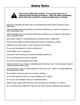
REPAIR PARTS FOR MODEL 486.24211 - 42" HIGH PERFORMANCE LAWNSWEEPER
r
64 18
63
64 48 4
8O
/ 50
\
52
84
96
65
t
%
91
92
78
24
74
"12
14
75
A
57
13
67
72
/
9
\
2
16
/
73
\
13'
J
7
47
29
38
32
B / 36
/ 37
29
14

REPAIR PARTS LIST FOR MODEL 486.24211 - 42" HIGH PERFORMANCE LAWNSWEEPER
REF. PART QTY
NO. NO.
1
2
3
4
5
6
7
8
9
10
11
!2
13
14
15
16
17
18
19
20
21
22
23
24
25
26
27
28
29
30
31
32
33
34
35
36
37
38
39
4O
41
42
43
44
45
46
47
48
49
46776 1
46777 1
24195 1
24196 t
24184 1
24185 1
C-9M5732 3O
46778 1
24186 1
63468 1
44947 2
_695 2
43086 12
43083 6
62489 2
44232 2
1629-56 2
24198 1
46780 4
43012 8
43013 18
23580 4
23581 8
44008 2
6249O 2
23573 2
47046 2
43655 2
1650-21 4
440O7 6
43t82 8
141 2
43070 2
1540-31 2
1540-107 2
1038 2
2674-32 2
43894 2
43932 2
23400 2
43890 1
43889 1
441.37 4
44542 2
43175 2
43661 4
62791 1
62792 1
46734 1
DESCRIPTION
HitchTube, R.H.
Hitch Tube, L.H.
End Plate, L.H.
End Plate, R.H.
Wrapper
Brace, Rear Support
Rivet, Pop
Skirt, 42"
Retainer, Skirt
Height Adjustment Tube Ass'y.
Bolt, Cvd. Hd. 5116-18 x 1-5/8" Lg.
Washer, Bowed 1" x .32" x .06'_
REF. PART QTY,
NO. NO.
50 146735
51 46732
52 46733
53 24189
54 43938
55 43737
56 24190
57 24191
58 23687
59 24192
60 24193
61 46781
_ i _
1
t
1
2 _
1
1
1
1
1
1
2
DESCRIPTION
Lock Washer, 5/16"
Nut, Hex 5/16-18 Thread
Brush Bushing Ass'y.
Ball Bearing
Retainer, Dust Cover
Brush Shaft
Brush, 42"
Bolt, Hex 1/4-20 x 3/4" Lg.
Nut, Hex Lock 1/4-20 Thread
Retainer, Brush (Double)
Retainer, Brush (Single)
62 46823 1
63 44985 2
64 45088 4
65 46782 2
66 43224 1
67 43064 8
68 46847 1
69 R19111116 2
70 43720 1
71 43080 1
72 43081 t
Washer, Flat 1-1/8" x .78" x .025" 73
Sprocket / Gear 74
Dust Cover 75
Dowel Pin (Drive) : 76
Ring, Retaining 3/4" 77
Ring, Retaining .594" 78
Washer, Shim1-1/8"x.594" x.025" 79
Bolt, Hex 5/16-18 x 3/4" Lg. 80
Washer, Flat 1-1/2" x .375" x .062" 81
Washer, 3/8" Std. Wrt. 82
Washer, Flat .78" x 1.25" x .06" 83
Washer, Flat .78" x 1.25" x .03t" 84
Nut, Hex Lock 3/8-24 Thread 85
Hub Cap 86
Ring, Retaining 1/2" 87
Bolt, Hex 3/8-24 x 3-1/2" Lg. 88
Bushing, Spacer 89
Sprocket, Ratchet R.H. (not shown) 90
Sprocket, Ratchet L.H. 91
Washer, 1/2" x 1" x .02" 92
Chain, Roller 93
Bolt, Hex 1/4-20 x 1/2" Lg. 94
Bolt, Hex 1/4-20 x 1" Lg. 95
Housing, Wheel Drive Ass'y. LH. 96
Housing, Wheel Drive Ass'y. R.H. 97
Tube, Upper Hopper Frame R.H.
43084 4
43943 1
44732 1
46816 1
23368 2
43343 1
23331 4
44917 2
43978 2
1509-90 2
43346 6
43662 6
43407 2
43082 3
44481 2
43055 2
46867 2
44292 1
44230 1
43350, 1
43070! 1
142 t
23684 1
46819 1
46739 1
46821 1
Tube, Upper Hopper Frame LH.
Tube, Lower Hopper Frame R.H.
Tube, Lower Hopper Frame L.H.
Strap, Bag Frame
Rod, Hopper Support 34"
Hopper Rope
Retainer, Bag
Strap, Height Adjustment
Bracket, Hitch
Bracket, Hitch (Straight)
Handle, Height Adjustment
Tube, Bag Arm
Rod, Hopper Bag Pivot
Wheel & Tire Ass'y. (with bearings)
Wheel Bearing
Bolt, Hex 5/16-18 x 3" Lg.
Bolt, Hex 5/16-18 x 2-1/4" Lg.
Nut, Hex Lock 5/16-18 Thread
Bushing, Spacer
Washer, Flat (5/16) 11/32" x 11/16"
Knob, Wing 5/16-18 Thread
Bolt, Carriage 5/16-18 x 3/4" Lg.
Washer, Flat 5/16" Std. Wrt.
Bolt, Hex 5/16-18 x 1-3/4" Lg.
Grip, Height Adjust
Washer, Tooth Lock 5/16"
Pin, Hitch
Tube, Hitch Spacer
Hairpin Cotter, 1/8" #4
Clamp, Hopper Mount
Palnut, 3/8"
Bolt, Cvd. Hd. 1/4-20 x 1" Lg.
Bolt, Hex 1/4-20 x 1-1/4" Lg.
Bolt, SI. Tr. Hd. #10-32 x 5/8" Lg.
Nut, Hex Lock #I0-32 SEMS
Bolt, Hex 3/8-16 x 3/4" Lg.
Nut, Hex Lock 3/8-16 Thread
Cap, Vinyl
Hairpin Cotter, 3/32" #3
Pin, Clevis 1/4" x 1-1/2" Lg.
Bolt, Hex 5/16-18 x 2-!/2" Lg.
Spring, Hitch Pin
Bolt, Carr_3/8-16 x 1"Lg.
Washer, 3/8" Std. Wrt.
Pin, Cotter 1/8" x 3/4" Lg.
Bracket, Hitch Pin
Hopper Bag
Wind Screen
Owners Manual
15

For repair of major brand appliances in your own home...
no matter who made it, no matter who sold it!
1-800-4-MY-HOMESMAnytime, day or night
(1-800-469-4663)
www.sears.com
To bring in products such as vacuums, lawn equipment and electronics
for repair, call for the location of your nearest Sears Parts & Repair Center.
1-800-488-1222 Anytime, day or night
www.sears.com
For the replacement parts, accessories and owner's manuals
that you need to do-it-yourself, call Sears PartsDirectSM !
1-800-366-PART 6a.m-11pmCST,
(1-800-366-7278) 7 days a week
www.sears.com/partsdirect
To purchase or inquire about a Sears Service Agreement:
1-800-827-6655
7 a.m. - 5 p.m. CST, Mon. - Sat.
(1-888-784-6427)
Para pedir servicio de reparaci6n a domicilio,
y para ordenar piezas con entrega a domicitio:
1"888"SU'HOGAR sM
Au Canada Pour service en fran£_ais:
1-877-LE-FOYER _M
(1-877-533-6937)
8££8 }
HomeCentral"
® RegisteredTrademarkt Trademarkof Sears, Roebuck endCo.
© Sears,Roebuckand Co. ® MarcaRegistradaI TM Mamade F#=bdcade Sears,Roebuckand Co,
/