Ford Mustang GT 1998 User manual
- Category
- Car alarm
- Type
- User manual

Before driving
Introduction 2
Instrumentation 4
Controls and features 16
Seating and safety restraints 63
Starting and driving
Starting 83
Driving 88
Roadside emergencies 108
Servicing
Maintenance and care 126
Capacities and specifications 177
Reporting safety defects 185
Index 186
All rights reserved. Reproduction by any means, electronic
or mechanical including photocopying, recording or by any
information storage and retrieval system or translation in
whole or part is not permitted without written
authorization from Ford Motor Company.
Copyright
r
1998 Ford Motor Company
Contents
1

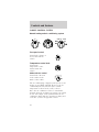
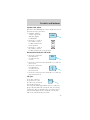
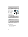
ICONS
Indicates a safety alert.
Read the following
section on Warnings.
Indicates vehicle
information related to
recycling and other
environmental
concerns will follow.
Correct vehicle usage and the authorized disposal of
waste cleaning and lubrication materials are
significant steps towards protecting the
environment.
Indicates a message
regarding child safety
restraints. Refer to
Seating and safety
restraints for more information.
Indicates that this
Owner Guide contains
information on this
subject. Please refer to
the Index to locate the appropriate section which
will provide you more information.
WARNINGS
Warnings provide information which may reduce the
risk of personal injury and prevent possible damage
to others, your vehicle and its equipment.
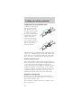
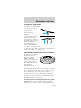
BREAKING-IN YOUR VEHICLE
There are no particular breaking-in rules for your
vehicle. During the first 1 600 km (1 000 miles) of
driving, vary speeds frequently. This is necessary to
give the moving parts a chance to break in.
Introduction
2

INFORMATION ABOUT THIS GUIDE
The information found in this guide was in effect at
the time of printing. Ford may change the contents
without notice and without incurring obligation.
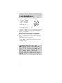
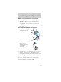
SPECIAL NOTICES
Notice to owners of Cobra vehicles
Before you drive your vehicle, be sure to read the
“SVT Cobra Owner’s Guide Supplement.” This book
contains important operation and maintenance
information.
Introduction
3

P
!
BRAKE
L
0
00000 00
C
E
F
H
LH
10
20
40
60
80
20
40
60
80
100
120 140
160
180
200
220
240
100
120
140
30
50
70 90
110
130
150
4
5
6
7
8
3
2
1
H
THEFT
REAR DEF
RPMX1000
FUEL DOOR
SELECT/RESET
LOW
FUEL
O/D
OFF
AIR
BAG
SERVICE
ENGINE
SOON
MPH km/h
ABS
.
OFF
HI
LO
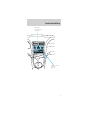
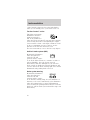
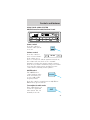
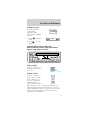
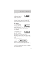
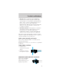
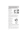
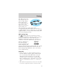
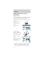
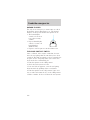
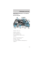
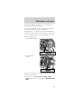
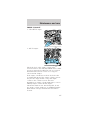
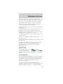
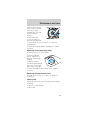
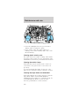
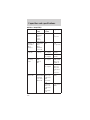
Headlamp control
(pg. 16)
Driver side air
bag
(pg. 71)
Turn signal and
wiper/washer
control
(pg. 43)
Instrument
cluster
(pg. 6)
Instrumentation
4

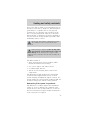
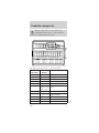
POWER AUDIO
VOLUME
AM/FM
REW
FF
PLAY
EJCT
1
2
3
4
5
CLOCK
AUTO
PRESET
PROG
AUTOMATIC
DNR CrO
2
SCAN
TUNE
SEEK
FM1
ST
LO
HI
OFF
FLOOR
MIX
VENT
NORM
A/C
MAX
A/C
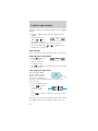
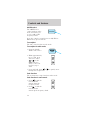
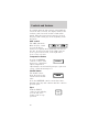
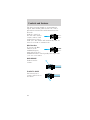
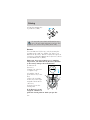
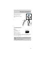
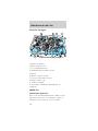
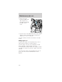
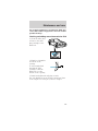
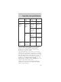
Climate control
systems
(pg. 18)
Electronic
sound system
(pg. 21)
Instrumentation
5

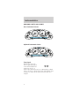
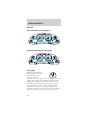
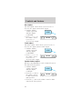
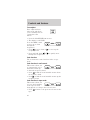
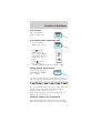
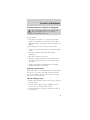
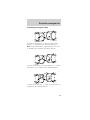
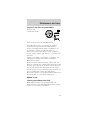
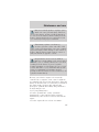
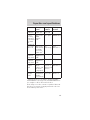
WARNING LIGHTS AND CHIMES
Base instrument cluster
Optional instrument cluster
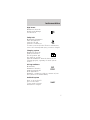
Turn signal
Illuminates when the
left or right turn signal
or the hazard lights are
turned on. If one or
both of the indicators stay on continuously or flash
faster, check for a burned-out turn signal bulb. Refer
to Exterior bulbs in the Maintenance and care
chapter.
P!
BRAKE
L
0
00000 00
C
E
F
H
LH
10
20
30
20
40
60
80
100
120
140
160
180
40
50
60 70
80
90
100
11 0
120
4
5
6
7
3
2
1
H
THEFT
RPMX1000
FUEL DOOR
SELECT/RESET
LOW
FUEL
O/D
OFF
AIR
BAG
SERVICE
ENGINE
SOON
MPH km/h
ABS
.
P!
BRAKE
L
0
00000 00
C
E
F
H
LH
10
20
40
60
80
20
40
60
80
100
120 14 0
160
180
200
220
240
100
120
140
30
50
70 90
110
130
150
4
5
6
7
8
3
2
1
H
THEFT
RPMX1000
FUEL DOOR
SELECT/RESET
LOW
FUEL
O/D
OFF
AIR
BAG
SERVICE
ENGINE
SOON
MPH km/h
ABS
.
Instrumentation
6

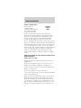
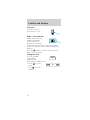
High beams
Illuminates when the
high beam headlamps
are turned on.
Safety belt
Momentarily illuminates
when the ignition is
turned to the ON
position to remind you
to fasten your safety belts. For more information,
refer to the Seating and safety restraints chapter.
Charging system
Illuminates when the
ignition is turned to
the ON position and
the engine is off. The
light also illuminates when the battery is not
charging properly, requiring electrical system
service.
Air bag readiness
Momentarily
illuminates when the
ignition is turned ON.
If the light fails to
illuminate, continues to flash or remains on, have
the system serviced immediately.
Anti-theft system
Refer to SecuriLocky
passive anti-theft
system in the Controls
and features chapter.
AIR
BAG
THEFT
Instrumentation
7

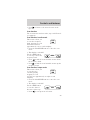
Service engine soon
Your vehicle is
equipped with a
computer that monitors
the engine’s emission
control system. This
system is commonly known as the On Board
Diagnostics System (OBD II). The OBD II system
protects the environment by ensuring that your
vehicle continues to meet government emission
standards. The OBD II system also assists the
service technician in properly servicing your vehicle.
The Service Engine Soon indicator light illuminates
when the ignition is first turned to the ON position
to check the bulb. If it comes on after the engine is
started, one of the engine’s emission control systems
may be malfunctioning. The light may illuminate
without a driveability concern being noted. The
vehicle will usually be drivable and will not require
towing.
What you should do if the Service Engine Soon
light illuminates
Light turns on solid:
This means that the OBD II system has detected a
malfunction.
Temporary malfunctions may cause your Service
Engine Soon light to illuminate. Examples are:
1. The vehicle has run out of fuel. (The engine may
misfire or run poorly.)
2. Poor fuel quality or water in the fuel.
3. The fuel cap may not have been properly installed
and securely tightened.
These temporary malfunctions can be corrected by
filling the fuel tank with good quality fuel and/or
properly installing and securely tightening the gas
cap. After three driving cycles without these or any
other temporary malfunctions present, the Service
Engine Soon light should turn off. (A driving cycle
SERVICE
ENGINE
SOON
Instrumentation
8

consists of a cold engine startup followed by mixed
city/highway driving.) No additional vehicle service is
required.
If the Service Engine Soon light remains on, have
your vehicle serviced at the first available
opportunity.
Light is blinking:
Engine misfire is occurring which could damage your
catalytic converter. You should drive in a moderate
fashion (avoid heavy acceleration and deceleration)
and have your vehicle serviced at the first available
opportunity.
Under engine misfire conditions, excessive
exhaust temperatures could damage the
catalytic converter, the fuel system, interior floor
coverings or other vehicle components, possibly
causing a fire.
Low fuel
Illuminates as an early
reminder of a low fuel
condition indicated on
the fuel gauge. The
light comes on when there is approximately 1/16th
of a tank indicated on the fuel gauge (refer to Fuel
Gauge in this chapter for more information). The
ignition must be in the ON position for this lamp to
illuminate. The lamp will also illuminate for several
seconds after the ignition is turned to the ON
position regardless of the fuel level.
O/D off (if equipped)
Illuminates when the
transmission control
switch has been
pushed. When the light
is on, the transmission does not shift into overdrive.
If the light does not come on when the transmission
LOW
FUEL
O/D
OFF
Instrumentation
9

control switch is depressed or if the light flashes
when you are driving, have your vehicle serviced.
Traction ControlY active
This light momentarily
illuminates when the
ignition is turned to
ON. It also illuminates
when the Traction Controly system begins applying
and releasing the brakes and adjusting the engine
characteristics to limit a wheelspin condition. It will
be lit for a minimum of four seconds or for the
duration of the Traction Controly event.
For more information, refer to the Driving chapter.
Anti-lock brake system (ABS)
Momentarily illuminates
when the ignition is
turned to the ON
position and the engine
is off. If the light remains on, continues to flash or
fails to illuminate, have the system serviced
immediately. With the ABS light on, the anti-lock
brake system is disabled and normal braking is still
effective unless the brake warning light also remains
illuminated with parking brake released.
Brake system warning
Momentarily illuminates
when the ignition is
turned to the ON
position and the engine
is off. If brake warning lamp does not illuminate at
this time, seek service immediately. Also illuminates
when the parking brake is engaged. Illumination
after releasing the parking brake indicates low brake
fluid level and the brake system should be inspected
immediately.
ABS
P!
BRAKE
Instrumentation
10

Check coolant
Illuminates when the
coolant level in the
coolant reservoir is low
and more needs to be
added. This lamp will also illuminate when the
ignition is turned to ON and the engine is off. For
more information on adding engine coolant, refer to
Engine coolant in the Maintenance and care
chapter.
Safety belt warning chime
Chimes to remind you to fasten your safety belts.
For information on the safety belt warning chime,
refer to the Seating and safety restraints chapter.
Supplemental restraint system (SRS) warning
chime
For information on the SRS warning chime, refer to
the Seating and safety restraints chapter.
Key-in-ignition warning chime
Sounds when the key is left in the ignition in the
OFF/LOCK or ACC position and the driver’s door is
opened.
Headlamps on warning chime
Sounds when the headlamps or parking lamps are
on, the ignition is off (and the key is not in the
ignition) and the driver’s door is opened.
Instrumentation
11

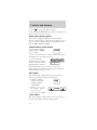
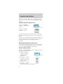
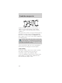
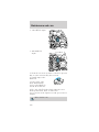
GAUGES
Base instrument cluster gauges
Optional instrument cluster gauges
Fuel gauge
Displays approximately
how much fuel is in the
fuel tank (when the
key is in the ON
position). The fuel gauge may vary slightly when the
vehicle is in motion. The ignition should be in the
OFF position while the vehicle is being refueled.
When the gauge first indicates empty, there is a
small amount of reserve fuel in the tank. When
refueling the vehicle from empty indication, the
amount of fuel that can be added will be less than
the advertised capacity due to the reserve fuel.
C
P!
BRAKE
L
0
00000 00
E F
LH
10
20
30
20
40
60
80
100
120
140
160
180
40
50
60 70
80
90
100
11 0
120
4
5
6
7
3
2
1
H
THEFT
RPMX1000
FUEL DOOR
SELECT/RESET
LOW
FUEL
O/D
OFF
AIR
BAG
SERVICE
ENGINE
SOON
MPH km/h
ABS
.
H
P!
BRAKE
0
00000 00
F
H
H
10
20
40
60
80
20
40
60
80
100
120 14 0
160
180
200
220
240
100
120
140
30
50
70 90
110
130
150
4
5
6
7
8
3
2
1
H
THEFT
RPMX1000
FUEL DOOR
SELECT/RESET
LOW
FUEL
O/D
OFF
AIR
BAG
SERVICE
ENGINE
SOON
MPH km/h
ABS
.
L
L
F
Instrumentation
12

Engine coolant temperature gauge
Indicates the
temperature of the
engine coolant. At
normal operating
temperature, the needle remains within the normal
area (the area between the “H” and “C”). If it enters
the red section, the engine is overheating. Stop the
vehicle as soon as safely possible, switch off the
engine immediately and let the engine cool. Refer to
Engine coolant in the Maintenance and care
chapter.
Never remove the coolant reservoir cap
while the engine is running or hot.
This gauge indicates the temperature of the engine
coolant, not the coolant level. If the coolant is not at
its proper level the gauge indication will not be
accurate.
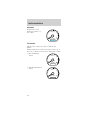
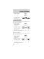
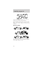
Speedometer
Indicates the current vehicle speed.
• Base instrument
cluster
• Optional instrument
cluster
C H
10
20
30
20
40
60
80
100
120
140
160
180
40
50
60 70
80
90
100
11 0
120
FUEL DOOR
MPH km/h
10
20
40
60
80
20
40
60
80
100
120 140
160
180
200
220
240
100
120
140
30
50
70 90
110
130
150
FUEL DOOR
MPH km/h
Instrumentation
13

Odometer
Registers the total
kilometers (miles) of
the vehicle.
Tachometer
Indicates the engine speed in revolutions per
minute.
Driving with your tachometer pointer at the top of
the scale or in the red zone may damage the engine.
• Base instrument
cluster
• Standard instrument
cluster
0
00000 00
4
5
6
7
8
3
2
1
RPMX1000
SELECT/RESET
.
0
00000 00
4
5
6
7
3
2
1
RPMX1000
SELECT/RESET
.
0
00000 00
4
5
6
7
8
3
2
1
RPMX1000
SELECT/RESET
.
Instrumentation
14

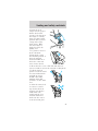
Trip odometer
Registers the
kilometers (miles) of
individual journeys.
Press the reset button
until a “T” appears in
the display (this
represents the trip
mode). Press and hold
the button for
2.5 seconds to reset.
Battery voltage gauge
This gauge shows the
battery voltage when
the ignition is in the
ON position. If the
pointer moves and stays outside the normal
operating range (as indicated), have the vehicle’s
electrical system checked as soon as possible.
Engine oil pressure gauge
This shows the engine
oil pressure in the
system. Sufficient
pressure exists as long
as the needle remains in the normal range (the area
between the “L” and “H”).
If the gauge indicates low pressure, stop the vehicle
as soon as safely possible and switch off the engine
immediately. Check the oil level. Add oil if needed
(refer to Engine oil in the Maintenance and care
chapter). If the oil level is correct, have your vehicle
checked at your dealership or by a qualified
technician.
0
00000 00
4
5
6
7
8
3
2
1
RPMX1000
SELECT/RESET
.
LH
L H
Instrumentation
15

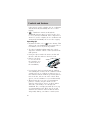
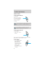
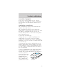
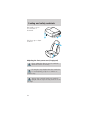
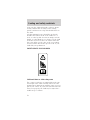
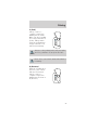
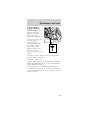
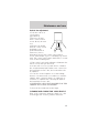
HEADLAMP CONTROL
• Pull the headlamp
control toward you
to the first position
to turn on the
parking lamps, tail
lamps, license plate
lamps and marker
lamps.
• Pull the headlamp control toward you to the outer
position to turn on the headlamps (in addition to
the previous lamps).
Daytime running lamps (DRL) (if equipped)
Turns the headlamps on with a reduced output. To
activate:
• the ignition must be turned on
• the headlamp control is in the OFF or Parking
lamps position
• the high beam headlamps must be turned off
• the parking brake is released
Always remember to turn on your
headlamps at dusk or during inclement
weather. The Daytime Running Light (DRL)
System does not activate your tail lamps and
generally may not provide adequate lighting during
these conditions. Failure to activate your
headlamps under these conditions may result in a
collision.
Controls and features
16

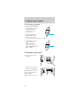
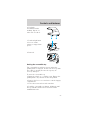
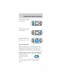
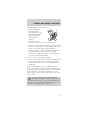
PANEL DIMMER CONTROL
To adjust the
brightness of the
instrument panel:
• Rotate clockwise/
counterclockwise
when the headlamp
control is in the
parking lamp or low-beam position.
To turn on the courtesy lamps:
• Rotate fully counterclockwise.
REAR WINDOW DEFROSTER (IF EQUIPPED)
The rear defroster
control is located on
the instrument panel.
Press the rear defroster control to clear the rear
window of thin ice and fog.
• The small LED will illuminate when the rear
defroster is activated.
The ignition must be in the ON position to operate
the rear window defroster.
The defroster turns off automatically after
10 minutes or when the ignition is turned to the
OFF position. To manually turn off the defroster
before ten minutes have passed, push the control
again.
REAR DEF
Controls and features
17

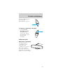
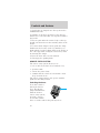
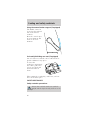
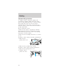
CLIMATE CONTROL SYSTEM
Manual heating and air conditioning system
Fan speed control
Controls the volume of
air circulated in the
vehicle.
Temperature control knob
Controls the
temperature of the
airflow inside the
vehicle.
Mode selector control
Controls the direction
of the airflow to the
inside of the vehicle.
The air conditioning compressor will operate in all
modes except VENT and FLR. However, the air
conditioning will only function if the outside
temperature is about 10°C (50°F) or above.
Since the air conditioner removes considerable
moisture from the air during operation, it is normal
if clear water drips on the ground under the air
conditioner drain while the system is working and
even after you have stopped the vehicle.
LO
HI
OFF
FLOOR
MIX
VENT
NORM
A/C
MAX
A/C
LO
HI
OFF
FLOOR
MIX
VENT
NORM
A/C
MAX
A/C
Controls and features
18

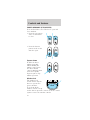
Under normal conditions, your vehicle’s climate
control system should be left in any position other
than MAX A/C or OFF when the vehicle is parked.
This allows the vehicle to “breathe” through the
outside air inlet duct.
• MAX A/C-Uses recirculated air to cool the vehicle.
MAX A/C is noisier than NORM A/C but more
economical and will cool the inside of the vehicle
faster. Airflow will be from the instrument panel
registers. This mode can also be used to reduce
undesirable odors from entering the vehicle.
• NORM A/C-Uses outside air to cool the vehicle. It
is quieter than MAX A/C but not as economical.
Airflow will be from the instrument panel
registers.
• VENT-Distributes outside air through the
instrument panel registers. However, the air will
not be cooled below the outside temperature
because the air conditioning does not operate in
this mode.
• OFF-Outside air is shut out and the fan will not
operate. For short periods of time only, use this
mode to prevent undesirable odors from entering
the vehicle.
• FLR-Allows for maximum heating by distributing
outside air through the floor ducts. However, the
air will not be cooled below the outside
temperature because the air conditioning does not
operate in this mode.
• MIX-Distributes outside air through the
windshield defroster ducts and the floor ducts.
Heating and air conditioning capabilities are
provided in this mode. For added customer
comfort, when the temperature control knob is
anywhere in between the full hot and full cold
positions, the air distributed through the floor
ducts will be slightly warmer than the air sent to
the windshield defroster ducts. If the temperature
Controls and features
19

is about 10°C (50°F) or higher, the air conditioner
will automatically dehumidify the air to reduce
fogging.
•
-
Distributes outside air through the
windshield defroster ducts. It can be used to clear
ice or fog from the windshield. If the temperature is
about 10°C (50°F) or higher, the air conditioner will
automatically dehumidify the air to reduce fogging.
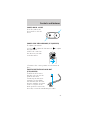
Operating tips
• In humid weather, select before driving. This
will prevent your windshield from fogging. After a
few minutes, select any desired position.
• To reduce humidity buildup inside the vehicle,
don’t drive with the climate control system in the
OFF position.
• Don’t put objects under the front seat that will
interfere with the airflow to the back seats.
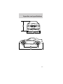
• Remove any snow,
ice or leaves from
the air intake area
(at the bottom of
the windshield).
•
If your vehicle has been parked with the windows
closed during hot weather, the air conditioner will do
a much faster job of cooling if you drive for two or
three minutes with the windows open. This will force
most of the hot, stale air out of the vehicle. Then
operate your air conditioner as you would normally.
•
When placing objects on top of your instrument
panel, be careful to not place them over the
defroster outlets. These objects can block airflow
and reduce your ability to see through your
windshield. Also, avoid placing small objects on top
of your instrument panel. These objects can fall
down into the defroster outlets and block airflow
and possibly damage your climate control system.
Controls and features
20
Page is loading ...
Page is loading ...
Page is loading ...
Page is loading ...
Page is loading ...
Page is loading ...
Page is loading ...
Page is loading ...
Page is loading ...
Page is loading ...
Page is loading ...
Page is loading ...
Page is loading ...
Page is loading ...
Page is loading ...
Page is loading ...
Page is loading ...
Page is loading ...
Page is loading ...
Page is loading ...
Page is loading ...
Page is loading ...
Page is loading ...
Page is loading ...
Page is loading ...
Page is loading ...
Page is loading ...
Page is loading ...
Page is loading ...
Page is loading ...
Page is loading ...
Page is loading ...
Page is loading ...
Page is loading ...
Page is loading ...
Page is loading ...
Page is loading ...
Page is loading ...
Page is loading ...
Page is loading ...
Page is loading ...
Page is loading ...
Page is loading ...
Page is loading ...
Page is loading ...
Page is loading ...
Page is loading ...
Page is loading ...
Page is loading ...
Page is loading ...
Page is loading ...
Page is loading ...
Page is loading ...
Page is loading ...
Page is loading ...
Page is loading ...
Page is loading ...
Page is loading ...
Page is loading ...
Page is loading ...
Page is loading ...
Page is loading ...
Page is loading ...
Page is loading ...
Page is loading ...
Page is loading ...
Page is loading ...
Page is loading ...
Page is loading ...
Page is loading ...
Page is loading ...
Page is loading ...
Page is loading ...
Page is loading ...
Page is loading ...
Page is loading ...
Page is loading ...
Page is loading ...
Page is loading ...
Page is loading ...
Page is loading ...
Page is loading ...
Page is loading ...
Page is loading ...
Page is loading ...
Page is loading ...
Page is loading ...
Page is loading ...
Page is loading ...
Page is loading ...
Page is loading ...
Page is loading ...
Page is loading ...
Page is loading ...
Page is loading ...
Page is loading ...
Page is loading ...
Page is loading ...
Page is loading ...
Page is loading ...
Page is loading ...
Page is loading ...
Page is loading ...
Page is loading ...
Page is loading ...
Page is loading ...
Page is loading ...
Page is loading ...
Page is loading ...
Page is loading ...
Page is loading ...
Page is loading ...
Page is loading ...
Page is loading ...
Page is loading ...
Page is loading ...
Page is loading ...
Page is loading ...
Page is loading ...
Page is loading ...
Page is loading ...
Page is loading ...
Page is loading ...
Page is loading ...
Page is loading ...
Page is loading ...
Page is loading ...
Page is loading ...
Page is loading ...
Page is loading ...
Page is loading ...
Page is loading ...
Page is loading ...
Page is loading ...
Page is loading ...
Page is loading ...
Page is loading ...
Page is loading ...
Page is loading ...
Page is loading ...
Page is loading ...
Page is loading ...
Page is loading ...
Page is loading ...
Page is loading ...
Page is loading ...
Page is loading ...
Page is loading ...
Page is loading ...
Page is loading ...
Page is loading ...
Page is loading ...
Page is loading ...
Page is loading ...
Page is loading ...
Page is loading ...
Page is loading ...
Page is loading ...
Page is loading ...
Page is loading ...
Page is loading ...
Page is loading ...
Page is loading ...
Page is loading ...
Page is loading ...
Page is loading ...
Page is loading ...
Page is loading ...
Page is loading ...
Page is loading ...
Page is loading ...
Page is loading ...
-
 1
1
-
 2
2
-
 3
3
-
 4
4
-
 5
5
-
 6
6
-
 7
7
-
 8
8
-
 9
9
-
 10
10
-
 11
11
-
 12
12
-
 13
13
-
 14
14
-
 15
15
-
 16
16
-
 17
17
-
 18
18
-
 19
19
-
 20
20
-
 21
21
-
 22
22
-
 23
23
-
 24
24
-
 25
25
-
 26
26
-
 27
27
-
 28
28
-
 29
29
-
 30
30
-
 31
31
-
 32
32
-
 33
33
-
 34
34
-
 35
35
-
 36
36
-
 37
37
-
 38
38
-
 39
39
-
 40
40
-
 41
41
-
 42
42
-
 43
43
-
 44
44
-
 45
45
-
 46
46
-
 47
47
-
 48
48
-
 49
49
-
 50
50
-
 51
51
-
 52
52
-
 53
53
-
 54
54
-
 55
55
-
 56
56
-
 57
57
-
 58
58
-
 59
59
-
 60
60
-
 61
61
-
 62
62
-
 63
63
-
 64
64
-
 65
65
-
 66
66
-
 67
67
-
 68
68
-
 69
69
-
 70
70
-
 71
71
-
 72
72
-
 73
73
-
 74
74
-
 75
75
-
 76
76
-
 77
77
-
 78
78
-
 79
79
-
 80
80
-
 81
81
-
 82
82
-
 83
83
-
 84
84
-
 85
85
-
 86
86
-
 87
87
-
 88
88
-
 89
89
-
 90
90
-
 91
91
-
 92
92
-
 93
93
-
 94
94
-
 95
95
-
 96
96
-
 97
97
-
 98
98
-
 99
99
-
 100
100
-
 101
101
-
 102
102
-
 103
103
-
 104
104
-
 105
105
-
 106
106
-
 107
107
-
 108
108
-
 109
109
-
 110
110
-
 111
111
-
 112
112
-
 113
113
-
 114
114
-
 115
115
-
 116
116
-
 117
117
-
 118
118
-
 119
119
-
 120
120
-
 121
121
-
 122
122
-
 123
123
-
 124
124
-
 125
125
-
 126
126
-
 127
127
-
 128
128
-
 129
129
-
 130
130
-
 131
131
-
 132
132
-
 133
133
-
 134
134
-
 135
135
-
 136
136
-
 137
137
-
 138
138
-
 139
139
-
 140
140
-
 141
141
-
 142
142
-
 143
143
-
 144
144
-
 145
145
-
 146
146
-
 147
147
-
 148
148
-
 149
149
-
 150
150
-
 151
151
-
 152
152
-
 153
153
-
 154
154
-
 155
155
-
 156
156
-
 157
157
-
 158
158
-
 159
159
-
 160
160
-
 161
161
-
 162
162
-
 163
163
-
 164
164
-
 165
165
-
 166
166
-
 167
167
-
 168
168
-
 169
169
-
 170
170
-
 171
171
-
 172
172
-
 173
173
-
 174
174
-
 175
175
-
 176
176
-
 177
177
-
 178
178
-
 179
179
-
 180
180
-
 181
181
-
 182
182
-
 183
183
-
 184
184
-
 185
185
-
 186
186
-
 187
187
-
 188
188
-
 189
189
-
 190
190
-
 191
191
-
 192
192


Ford Mustang GT 1998 User manual
- Category
- Car alarm
- Type
- User manual
Ask a question and I''ll find the answer in the document
Finding information in a document is now easier with AI
Related papers
-
Ford 2002 Taurus Owner's manual
-
Ford 2002 Taurus Owner's manual
-
-
-
-
-
-
-
-
Other documents
-
Lincoln 2002 Blackwood Owner's manual
-
 Bentley Continental Owner's manual
-
Mercury 2002 Sable Owner's manual
-
-
Mazda Tribute 2001 Owner's manual
-
Lincoln Navigator Owner's manual
-
-
-
-
