Gigabyte GA-A75M-DS2 Owner's manual
- Category
- Motherboards
- Type
- Owner's manual
This manual is also suitable for

GA-A75M-DS2
User's Manual
Rev. 2001
12ME-A75MDS2-2001R

Motherboard
GA-A75M-DS2
Mar. 30, 2012
Mar. 30, 2012
Motherboard
GA-A75M-DS2

Copyright
© 2012 GIGA-BYTE TECHNOLOGY CO., LTD. All rights reserved.
The trademarks mentioned in this manual are legally registered to their respective owners.
Disclaimer
Information in this manual is protected by copyright laws and is the property of GIGABYTE.
Changes to the specications and features in this manual may be made by GIGABYTE with-
out prior notice. No part of this manual may be reproduced, copied, translated, transmitted, or
published in any form or by any means without GIGABYTE's prior written permission.
In order to assist in the use of this product, carefully read the User's Manual.
For product-related information, check on our website at: http://www.gigabyte.com
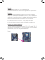
Identifying Your Motherboard Revision
The revision number on your motherboard looks like this: "REV: X.X." For example, "REV: 1.0"
means the revision of the motherboard is 1.0. Check your motherboard revision before updating
motherboard BIOS, drivers, or when looking for technical information.
Example:

- 4 -
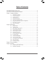
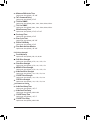
Table of Contents
GA-A75M-DS2 Motherboard Layout ...............................................................................5
GA-A75M-DS2 Motherboard Block Diagram ..................................................................6
Chapter 1 Hardware Installation .....................................................................................7
1-1 Installation Precautions ................................................................................... 7
1-2 Product Specications ..................................................................................... 8
1-3 Installing the APU .......................................................................................... 10
1-4 Installing the Memory .....................................................................................11
1-5 Installing an Expansion Card ..........................................................................11
1-6 Setup of the AMD Dual Graphics Conguration ........................................... 12
1-7 Back Panel Connectors ................................................................................. 13
1-8 Internal Connectors ....................................................................................... 14
Chapter 2 BIOS Setup ..................................................................................................21
2-1 Startup Screen ............................................................................................... 21
2-2 The Main Menu .............................................................................................. 22
2-3 MB Intelligent Tweaker(M.I.T.) ....................................................................... 23
2-4 Standard CMOS Features ............................................................................. 28
2-5 Advanced BIOS Features .............................................................................. 29
2-6 Integrated Peripherals ................................................................................... 30
2-7 Power Management Setup ............................................................................ 32
2-8 PC Health Status ........................................................................................... 34
2-9 Load Fail-Safe Defaults ................................................................................. 35
2-10 Load Optimized Defaults ............................................................................... 35
2-11 Set Supervisor/User Password .....................................................................36
2-12 Save & Exit Setup .......................................................................................... 36
2-13 Exit Without Saving........................................................................................ 37
Chapter 3 Drivers Installation .......................................................................................37
Chapter 4 Appendix ......................................................................................................38
4-1 Conguring SATA Hard Drive(s) .................................................................... 38
4-2 Regulatory Statements .................................................................................. 40

- 5 -
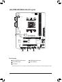
GA-A75M-DS2 Motherboard Layout
Box Contents
GA-A75M-DS2 motherboard Motherboard driver disk
Two SATA cables User's Manual
I/O Shield
* The box contents above are for reference only and the actual items shall depend on the product package you obtain.
KB_MS_USB
CPU_FAN
ATX
GA-A75M-DS2
AUDIO
B_BIOS
DDR3_1
DDR3_2
BAT
F_PANEL
ATX_12V
DVI
CODEC
CLR_CMOS
M_BIOS
VGA
USB_LAN
PCIEX16
PCIEX1
F_AUDIO
iTE
Su per
I/O
Socket FM1
R_USB30
AMD A75
Realtek/Atheros
GbE LAN
PCI
F_USB30SYS_FAN
SPDIF_O
F_USB2
F_USB1
3
2
SATA3
1
0
SATA3

- 6 -
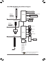
GA-A75M-DS2 Motherboard Block Diagram
For detailed product information/limitation(s),
refer to "1-2 Product Specications."
UMI
APU CLK+/- (100 MHz)
Dual Channel Memory
PCI Express Bus
PCIe CLK
(100 MHz)
1 PCI Express x16
iTE
Super
I/O
LPC
Bus
Dual BIOS
PS/2 KB/Mouse
D-Sub
x16
8 USB 2.0/1.1
DVI-D
4 SATA 6Gb/s
AMD APU
DISP CLK+/- (100 MHz)
Line Out (Front Speaker Out)
MIC (Center/Subwoofer Speaker Out)
Line In (Rear Speaker Out)
CODEC
S/PDIF Out
AMD A75
4 USB 3.0/2.0
PCI Bus
1 PCI
PCI CLK
(33 MHz)
PCI Express Bus
PCIe CLK
(100 MHz)
LAN
RJ45
x1
Realtek/Atheros
GbE LAN
x1
1 PCI Express x1
DDR3 2400 (O.C.)/1866/1600/1333/1066 MHz

- 7 -
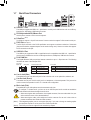
1-1 Installation Precautions
The motherboard contains numerous delicate electronic circuits and components which can
become damaged as a result of electrostatic discharge (ESD). Prior to installation, carefully read
the user's manual and follow these procedures:
Prior to installation, make sure the chassis is suitable for the motherboard. •
Prior to installation, do not remove or break motherboard S/N (Serial Number) sticker or •
warranty sticker provided by your dealer. These stickers are required for warranty validation.
Always remove the AC power by unplugging the power cord from the power outlet before •
installing or removing the motherboard or other hardware components.
When connecting hardware components to the internal connectors on the motherboard, •
make sure they are connected tightly and securely.
When handling the motherboard, avoid touching any metal leads or connectors. •
It is best to wear an electrostatic discharge (ESD) wrist strap when handling electronic com- •
ponents such as a motherboard, APU or memory. If you do not have an ESD wrist strap,
keep your hands dry and rst touch a metal object to eliminate static electricity.
Prior to installing the motherboard, please have it on top of an antistatic pad or within an •
electrostatic shielding container.
Before unplugging the power supply cable from the motherboard, make sure the power sup- •
ply has been turned off.
Before turning on the power, make sure the power supply voltage has been set according to •
the local voltage standard.
Before using the product, please verify that all cables and power connectors of your hard- •
ware components are connected.
To prevent damage to the motherboard, do not allow screws to come in contact with the •
motherboard circuit or its components.
Make sure there are no leftover screws or metal components placed on the motherboard or •
within the computer casing.
Do not place the computer system on an uneven surface •
.
Do not place the computer system in a high-temperature environment. •
Turning on the computer power during the installation process can lead to damage to sys- •
tem components as well as physical harm to the user.
If you are uncertain about any installation steps or have a problem related to the use of the •
product, please consult a certied computer technician.
Chapter 1 Hardware Installation

- 8 -
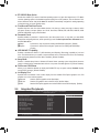
1-2 ProductSpecications
APU FM1 Socket:
- AMD A series processors/AMD E2 series processors
- AMD Athlon™ II processors/Sempron™ processors
(Go to GIGABYTE's website for the latest APU support list.)
Chipset AMD A75
Memory 2 x 1.5V DDR3 DIMM sockets supporting up to 32 GB of system memory
* Due to Windows 32-bit operating system limitation, when more than 4 GB of physical
memory is installed, the actual memory size displayed will be less than 4 GB.
Dual channel memory architecture
Support for DDR3 2400 (O.C.)/1866/1600/1333/1066 MHz memory modules
(Go to GIGABYTE's website for the latest supported memory speeds and memory
modules.)
Onboard
Graphics
APU:
- 1 x D-Sub port
- 1 x DVI-D port, supporting a maximum resolution of 1920x1200
* The DVI-D port does not support D-Sub connection by adapter.
(The integrated graphics ports do not support Hot plug. If you want to change to
another graphics port when the computer is on, be sure to turn off the computer
rst.)
Audio
Realtek/VIA HD audio codec
High Denition Audio
2/4/5.1/7.1-channel
* To congure 7.1-channel audio, you have to use an HD front panel audio module
and enable the multi-channel audio feature through the audio driver.
Support for S/PDIF Out
LAN
Realtek/Atheros GbE LAN chip (10/100/1000 Mbit)
Expansion Slots 1 x PCI Express x16 slot, running at x16
1 x PCI Express x1 slot
(The PCI Express slots conform to the PCI Express 2.0 standard.)
1 x PCI slot
Multi-Graphics
Technology
Support for AMD Dual Graphics technology
* Only A series APUs support AMD Dual Graphics.
Storage Interface Chipset:
- 4 x SATA 6Gb/s connectors supporting up to 4 SATA 6Gb/s devices
- Support for RAID 0, RAID 1, RAID 10, and JBOD
USB Chipset:
- Up to 8 USB 2.0/1.1 ports (4 ports on the back panel, 4 ports available
through the internal USB headers)
- Up to 4 USB 3.0/2/0 ports (2 ports on the back panel, 2 ports available
through the internal USB header)
Internal
Connectors
1 x 24-pin ATX main power connector
1 x 4-pin ATX 12V power connector
4 x SATA 6Gb/s connectors

- 9 -
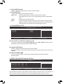
Internal
Connectors
1 x APU fan header
1 x system fan header
1 x front panel header
1 x front panel audio header
1 x S/PDIF Out header
2 x USB 2.0/1.1 headers
1 x USB 3.0/2.0 header
1 x Clear CMOS jumper
Back Panel
Connectors
1 x PS/2 keyboard/mouse port
1 x D-Sub port
1 x DVI-D port
4 x USB 2.0/1.1 ports
2 x USB 3.0/2.0 ports
1 x RJ-45 port
3 x audio jacks (Line In/Line Out/Microphone)
I/O Controller iTE I/O controller chip
Hardware
Monitor
System voltage detection
APU/System temperature detection
APU/System fan speed detection
APU overheating warning
APU/System fan fail warning
APU/System fan speed control
* Whether the APU/system fan speed control function is supported will depend on the
APU/system cooler you install.
BIOS 2 x 32 Mbit ash
Use of licensed AWARD BIOS
Support for DualBIOS
™
PnP 1.0a, DMI 2.0, SM BIOS 2.4, ACPI 1.0b
Unique Features Support for @BIOS
Support for Q-Flash
Support for Xpress BIOS Rescue
Support for Download Center
Support for Xpress Install
Support for Xpress Recovery2
Support for EasyTune
* Available functions in EasyTune may differ by motherboard model.
Support for Smart Recovery
Support for Auto Green
Support for ON/OFF Charge
Support for 3TB+ Unlock
Support for Q-Share

- 10 -
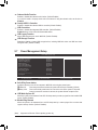
Bundled
Software
Norton Internet Security (OEM version)
Operating
System
Support for Microsoft
®
Windows 7/Vista/XP
Form Factor Micro ATX Form Factor; 22.5cm x 17.4cm
* GIGABYTE reserves the right to make any changes to the product specications and product-related information
without prior notice.
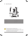
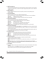
1-3 Installing the APU
Installing the APU
A. Locate the pin one (denoted by a small triangle) of the APU socket and the APU.
Read the following guidelines before you begin to install the APU:
• Make sure that the motherboard supports the APU.
(Go to GIGABYTE's website for the latest APU support list.)
• Always turn off the computer and unplug the power cord from the power outlet before installing
the APU to prevent hardware damage.
• Locate the pin one of the APU. The APU cannot be inserted if oriented incorrectly.
• Apply an even and thin layer of thermal grease on the surface of the APU.
• Do not turn on the computer if the APU cooler is not installed, otherwise overheating and dam-
age of the APU may occur.
• Set the APU host frequency in accordance with the APU specications. It is not recommended
that the system bus frequency be set beyond hardware specications since it does not meet the
standard requirements for the peripherals. If you wish to set the frequency beyond the standard
specications, please do so according to your hardware specications including the APU, graph-
ics card, memory, hard drive, etc.
APU
A Small Triangle Marking
Denotes APU Pin One
FM1 Socket
A Small Triangle Mark
Denotes Pin One of the
Socket

- 11 -
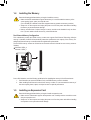
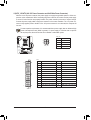
1-4 Installing the Memory
Due to APU limitations, read the following guidelines before installing the memory in Dual Channel mode.
Dual Channel mode cannot be enabled if only one DDR3 memory module is installed.1.
When enabling Dual Channel mode with two memory modules, it is recommended that memory of 2.
the same capacity, brand, speed, and chips be used for optimum performance.
DualChannelMemoryConguration
This motherboard provides two DDR3 memory sockets and supports Dual Channel Technology. After the
memory is installed, the BIOS will automatically detect the specications and capacity of the memory. En-
abling Dual Channel memory mode will double the original memory bandwidth.
The two DDR3 memory sockets are divided into two channels and each channel has one memory socket as
following:
Channel 0: DDR3_2
Channel 1: DDR3_1
Read the following guidelines before you begin to install the memory:
Make sure that the motherboard supports the memory. It is recommended that memory of the •
same capacity, brand, speed, and chips be used.
(Go to GIGABYTE's website for the latest supported memory speeds and memory modules.)
Always turn off the computer and unplug the power cord from the power outlet before installing •
the memory to prevent hardware damage.
Memory modules have a foolproof design. A memory module can be installed in only one direc- •
tion. If you are unable to insert the memory, switch the direction.
1-5 Installing an Expansion Card
Read the following guidelines before you begin to install an expansion card:
Make sure the motherboard supports the expansion card. Carefully read the manual that came •
with your expansion card.
Always turn off the computer and unplug the power cord from the power outlet before installing •
an expansion card to prevent hardware damage.
DDR3_2
DDR3_1

- 12 -
1-6 SetupoftheAMDDualGraphicsConguration
(Note) Make sure the drivers for the Chipset, onboard graphics, and external graphics card are properly
installed.
Combining the onboard GPU with a discrete graphics card, AMD's Dual Graphics technology can provide
signicantly advanced display performance for AMD platform. Read the following instructions on conguring a
Dual Graphics system.
A. System Requirements
- AMD A series processor
- Windows 7 operating system
- An AMD Dual Graphics technology-supported motherboard (with the BIOS updated to the latest version)
and correct driver (make sure the onboard graphics driver version is Rev. 8.881 or above)
- An AMD
Radeon HD 6000 series graphics card that supports AMD
Dual Graphics technology (for more
details, please visit AMD's ofcial website
)
and correct driver
B.InstallingtheGraphicsCardsandConguringBIOSSetup
Step 1:
Observe the steps in "1-5 Installing an Expansion Card" and install an AMD Dual Graphics technology-sup-
ported graphics card on the PCIEX16 slot. Plug the monitor cable into the graphics card or the motherboard
internal graphic port and start up your computer.
Step 2:
Enter BIOS Setup to set the following items under the AdvancedBIOSFeatures menu:
- Set Internal Graphics Mode to UMA.
- Set UMAFrameBufferSize to 512MB or 1024MB.
Save the settings and exit BIOS Setup. Restart your computer.
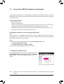
C.ConguringtheGraphicsDriver
After installing the graphics card driver in the operating system, go to
the AMDVISIONEngineControlCenter. Browse to Performance\
AMDCrossFire
™
and ensure the EnableCrossFire
™
check box is
selected.

- 13 -
1-7 Back Panel Connectors
USB 2.0/1.1 Port
The USB port supports the USB 2.0/1.1 specication. Use this port for USB devices such as a USB key-
board/mouse, USB printer, USB ash drive and etc.
PS/2 Keyboard and PS/2 Mouse Port
Use this port to connect a PS/2 mouse or keyboard.
D-Sub Port
(Note1)
The D-Sub port supports a 15-pin D-Sub connector. Connect a monitor that supports D-Sub connection to this port.
DVI-D Port
(Note1)(Note2)
The DVI-D port conforms to the DVI-D specication and supports a maximum resolution of 1920x1200
(the actual resolutions supported depend on the monitor being used). Connect a monitor that supports
DVI-D connection to this port.
USB 3.0/2.0 Port
The USB 3.0 port supports the USB 3.0 specication and is compatible to the USB 2.0/1.1 specication.
Use this port for USB devices such as a USB keyboard/mouse, USB printer, USB ash drive and etc.
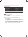
RJ-45LANPort
The Gigabit Ethernet LAN port provides Internet connection at up to 1 Gbps data rate. The following
describes the states of the LAN port LEDs.
(Note 1) Thel integrated graphics ports do not support Hot plug. If you want to change to another graphics
port when the computer is on, be sure to turn off the computer rst.
(Note 2) The DVI-D port does not support D-Sub connection by adapter.
Activity LED:
State Description
Blinking Data transmission or receiving is occurring
Off No data transmission or receiving is occurring
Connection/Speed LED:
State Description
Orange 1 Gbps data rate
Green 100 Mbps data rate
Off 10 Mbps data rate
Activity LED
Connection/
Speed LED
LAN Port
LineInJack(Blue)
The default line in jack. Use this audio jack for line in devices such as an optical drive, walkman, etc.
LineOutJack(Green)
The default line out jack. Use this audio jack for a headphone or 2-channel speaker. This jack can be
used to connect front speakers in a 4/5.1/7.1-channel audio conguration.
MicInJack(Pink)
The default Mic in jack. Microphones must be connected to this jack.
To congure 7.1-channel audio, you have to use an HD front panel audio module and enable the
multi-channel audio feature through the audio driver.
When removing the cable connected to a back panel connector, rst remove the cable from your •
device and then remove it from the motherboard.
When removing the cable, pull it straight out from the connector. Do not rock it side to side to •
prevent an electrical short inside the cable connector.

- 14 -
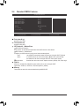
1-8 Internal Connectors
Read the following guidelines before connecting external devices:
First make sure your devices are compliant with the connectors you wish to connect. •
Before installing the devices, be sure to turn off the devices and your computer. Unplug the •
power cord from the power outlet to prevent damage to the devices.
After installing the device and before turning on the computer, make sure the device cable has •
been securely attached to the connector on the motherboard.
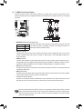
1) ATX_12V
2) ATX
3) CPU_FAN
4) SYS_FAN
5) SATA3 0/1/2/3
6) F_PANEL
7) F_AUDIO
8) SPDIF_O
9) F_USB1/F_USB2
10) F_USB30
11) CLR_CMOS
12) BAT
1
2
5
3
6
12
10
5
9987 114

- 15 -
DEBUG
PORT
G.QBOFM
131
2412
ATX
ATX:
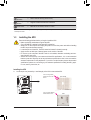
1/2)ATX_12V/ATX(2x212VPowerConnectorand2x12MainPowerConnector)
With the use of the power connector, the power supply can supply enough stable power to all the com-
ponents on the motherboard. Before connecting the power connector, rst make sure the power supply
is turned off and all devices are properly installed. The power connector possesses a foolproof design.
Connect the power supply cable to the power connector in the correct orientation. The 12V power con-
nector mainly supplies power to the APU. If the 12V power connector is not connected, the computer will
not start.
To meet expansion requirements, it is recommended that a power supply that can withstand high
power consumption be used (500W or greater). If a power supply is used that does not provide
the required power, the result can lead to an unstable or unbootable system.
ATX_12V:
Pin No. Denition
1 GND
2 GND
3 +12V
4 +12V
Pin No. Denition Pin No. Denition
1 3.3V 13 3.3V
2 3.3V 14 -12V
3 GND 15 GND
4 +5V 16 PS_ON (soft On/Off)
5 GND 17 GND
6 +5V 18 GND
7 GND 19 GND
8 Power Good 20 -5V
9 5VSB (stand by +5V) 21 +5V
10 +12V 22 +5V
11 +12V (Only for 2x12-pin ATX) 23 +5V (Only for 2x12-pin ATX)
12 3.3V (Only for 2x12-pin ATX) 24 GND (Only for 2x12-pin ATX)
ATX_12V
34
12

- 16 -
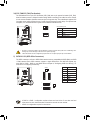
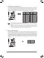
3/4)CPU_FAN/SYS_FAN(FanHeaders)
The motherboard has a 4-pin CPU fan header (CPU_FAN) and a 4-pin system fan header (SYS_FAN).
Most fan headers possess a foolproof insertion design. When connecting a fan cable, be sure to connect
it in the correct orientation (the black connector wire is the ground wire). The motherboard supports APU
fan speed control, which requires the use of a APU fan with fan speed control design. For optimum heat
dissipation, it is recommended that a system fan be installed inside the chassis.
Be sure to connect fan cables to the fan headers to prevent your APU and system from overheating. Over- •
heating may result in damage to the APU or the system may hang.
These fan headers are not conguration jumper blocks. Do not place a jumper cap on the headers. •
Pin No. Denition
1 GND
2 +12V
3 Sense
4 Speed Control
5) SATA30/1/2/3(SATA6Gb/sConnectors)
The SATA connectors conform to SATA 6Gb/s standard and are compatible with SATA 3Gb/s and SATA
1.5Gb/s standard. Each SATA connector supports a single SATA device. The AMD A75 Chipset sup-
ports RAID 0, RAID 1, RAID 10, and JBOD. Refer to Chapter 4, "Conguring SATA Hard Drive(s)," for
instructions on conguring a RAID array.
Pin No. Denition
1 GND
2 TXP
3 TXN
4 GND
5 RXN
6 RXP
7 GND
• A RAID 0 or RAID 1 conguration requires at least two hard drives. If more than two hard
drives are to be used, the total number of hard drives must be an even number.
• A RAID 10 conguration requires four hard drives.
CPU_FAN/SYS_FAN:
CPU_FAN
DEBUG
PORT
G.QBOFM
1
DEBUG
PORT
G.QBOFM
SYS_FAN
1
SATA3
1
0
3 2
1
7
DEBUG
PORT
G.QBOFM
DEBUG
PORT
G.QBOFM
DEBUG
PORT
G.QBOFM
DEBUG
PORT
G.QBOFM
1
7
7
1
1
7

- 17 -
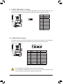
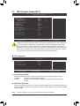
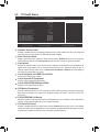
6) F_PANEL(FrontPanelHeader)
Connect the power switch, reset switch, speaker, and system status indicator on the chassis to this
header according to the pin assignments below. Note the positive and negative pins before connecting
the cables.
The front panel design may differ by chassis. A front panel module mainly consists of power
switch, reset switch, power LED, hard drive activity LED, speaker and etc. When connecting your
chassis front panel module to this header, make sure the wire assignments and the pin assign-
ments are matched correctly.
• PW (Power Switch):
Connects to the power switch on the chassis front panel. You may congure the way to turn off your
system using the power switch (refer to Chapter 2, "BIOS Setup," "Power Management Setup," for
more information).
• SPEAK (Speaker):
Connects to the speaker on the chassis front panel. The system reports system startup status by is-
suing a beep code. One single short beep will be heard if no problem is detected at system startup. If
a problem is detected, the BIOS may issue beeps in different patterns to indicate the problem.
• HD (Hard Drive Activity LED)
Connects to the hard drive activity LED on the chassis front panel. The LED is on when the hard drive
is reading or writing data.
• RES (Reset Switch):
Connects to the reset switch on the chassis front panel. Press the reset switch to restart the computer
if the computer freezes and fails to perform a normal restart.
• CI (Chassis Intrusion Header):
Connects to the chassis intrusion switch/sensor on the chassis that can detect if the chassis cover
has been removed. This function requires a chassis with a chassis intrusion switch/sensor.
• MSG/PWR (Message/Power/Sleep LED):
Connects to the power status indicator on the chassis front panel. The LED
is on when the system is operating. The LED is off when the system is in
S3/S4 sleep state or powered off (S5).
System Status LED
S0 On
S3/S4/S5 Off
1
2
19
20
MSG-
PW-
SPEAK+
SPEAK-
MSG+
PW+
Message/Power/
Sleep LED
HD-
RES+
HD+
RES-
Hard Drive
Activity LED
Reset
Switch
Speaker
F_USB30
F_AUDIO(H)
DB_PORT
F_PANEL(NH) F_PANEL
(H61M-D2)
ACPI_CPT
(GA-IVB)
BIOS_PH
(GA-IVB)
SMB_CPT
(GA-IVB)
CLR_CMOS
CI
DIS_ME
GP15_CPT
(GA-IVB)
XDP_CPU
XDP_PCH
(GA-IVB)
TPM
w/housing
Voltage measurement module(X58A-OC)
PCIe power connector (SATA)(X58A-OC)
DIP
1 2 3
DIP
1 2 3
DIP
1 2 3
DIP
123
1
1
1
1
BIOS Switcher (X58A-OC)
PWM Switch (X58A-OC)
M_SATA
PWM Switch (SW1)(X79-UD7)
DIP
1 2 3 4 5
Voltage measurement points(G1.Sniper 3)
BIOS Switcher (SW4)
Power
Switch
Power LED
CI-
CI+
PWR-
PWR+
Chassis Intrusion
Header

- 18 -
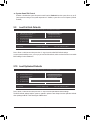
7) F_AUDIO(FrontPanelAudioHeader)
The front panel audio header supports Intel High Denition audio (HD) and AC'97 audio. You may connect
your chassis front panel audio module to this header. Make sure the wire assignments of the module con-
nector match the pin assignments of the motherboard header. Incorrect connection between the module
connector and the motherboard header will make the device unable to work or even damage it.
The front panel audio header supports HD audio by default. •
Audio signals will be present on both of the front and back panel audio connections simultane- •
ously.
Some chassis provide a front panel audio module that has separated connectors on each wire •
instead of a single plug. For information about connecting the front panel audio module that
has different wire assignments, please contact the chassis manufacturer.
For HD Front Panel Audio: For AC'97 Front Panel Audio:
Pin No. Denition
1 MIC2_L
2 GND
3 MIC2_R
4 -ACZ_DET
5 LINE2_R
6 GND
7 FAUDIO_JD
8 No Pin
9 LINE2_L
10 GND
Pin No. Denition
1 MIC
2 GND
3 MIC Power
4 NC
5 Line Out (R)
6 NC
7 NC
8 No Pin
9 Line Out (L)
10 NC
8) SPDIF_O(S/PDIFOutHeader)
This header supports digital S/PDIF Out and connects a S/PDIF digital audio cable (provided by expan-
sion cards) for digital audio output from your motherboard to certain expansion cards like graphics cards
and sound cards. For example, some graphics cards may require you to use a S/PDIF digital audio cable
for digital audio output from your motherboard to your graphics card if you wish to connect an HDMI
display to the graphics card and have digital audio output from the HDMI display at the same time. For
information about connecting the S/PDIF digital audio cable, carefully read the manual for your expan-
sion card.
Pin No. Denition
1 SPDIFO
2 GND
1
1
2
9
10

- 19 -
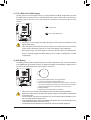
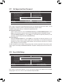
9) F_USB1/F_USB2(USB2.0/1.1Headers)
The headers conform to USB 2.0/1.1 specication. Each USB header can provide two USB ports via an
optional USB bracket. For purchasing the optional USB bracket, please contact the local dealer.
Do not plug the IEEE 1394 bracket (2x5-pin) cable into the USB header. •
Prior to installing the USB bracket, be sure to turn off your computer and unplug the power •
cord from the power outlet to prevent damage to the USB bracket.
Pin No. Denition
1 Power (5V)
2 Power (5V)
3 USB DX-
4 USB DY-
5 USB DX+
6 USB DY+
7 GND
8 GND
9 No Pin
10 NC
10
9
2
1
10) F_USB30(USB3.0/2.0Header)
The header conforms to USB 3.0/2.0 specication and can provide two USB ports. For purchasing the
optional 3.5" front panel that provides two USB 3.0/2.0 ports, please contact the local dealer.
Pin No. Denition Pin No. Denition
1 VBUS 11 D2+
2 SSRX1- 12 D2-
3 SSRX1+ 13 GND
4 GND 14 SSTX2+
5 SSTX1- 15 SSTX2-
6 SSTX1+ 16 GND
7 GND 17 SSRX2+
8 D1- 18 SSRX2-
9 D1+ 19 VBUS
10 NC 20 No Pin
F_USB30
F_AUDIO(H)
DB_PORT
F_PANEL(NH) F_PANEL
(H61M-D2)
ACPI_CPT
(GA-IVB)
BIOS_PH
(GA-IVB)
SMB_CPT
(GA-IVB)
CLR_CMOS
CI
DIS_ME
GP15_CPT
(GA-IVB)
XDP_CPU
XDP_PCH
(GA-IVB)
TPM
w/housing
Voltage measurement module(X58A-OC)
PCIe power connector (SATA)(X58A-OC)
DIP
1 2 3
DIP
1 2 3
DIP
1 2 3
DIP
123
1
1
1
1
BIOS Switcher (X58A-OC)
PWM Switch (X58A-OC)
M_SATA
PWM Switch (SW1)(X79-UD7)
DIP
1 2 3 4 5
Voltage measurement points(G1.Sniper 3)
BIOS Switcher (SW4)
20
10
11
1

- 20 -
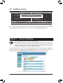
11) CLR_CMOS(ClearCMOSJumper)
Use this jumper to clear the CMOS values (e.g. date information and BIOS congurations) and reset
the CMOS values to factory defaults. To clear the CMOS values, place a jumper cap on the two pins to
temporarily short the two pins or use a metal object like a screwdriver to touch the two pins for a few
seconds.
Always turn off your computer and unplug the power cord from the power outlet before clear- •
ing the CMOS values.
After clearing the CMOS values and before turning on your computer, be sure to remove the •
jumper cap from the jumper. Failure to do so may cause damage to the motherboard.
After system restart, go to BIOS Setup to load factory defaults (select Load Optimized De- •
faults) or manually congure the BIOS settings (refer to Chapter 2, "BIOS Setup," for BIOS
congurations).
Open: Normal
Short: Clear CMOS Values
12) BAT(Battery)
The battery provides power to keep the values (such as BIOS congurations, date, and time information)
in the CMOS when the computer is turned off. Replace the battery when the battery voltage drops to a
low level, or the CMOS values may not be accurate or may be lost.
You may clear the CMOS values by removing the battery:
Turn off your computer and unplug the power cord.1.
Gently remove the battery from the battery holder and wait for one minute. 2.
(Or use a metal object like a screwdriver to touch the positive and negative
terminals of the battery holder, making them short for 5 seconds.)
Replace the battery. 3.
Plug in the power cord and restart your computer.4.
Always turn off your computer and unplug the power cord before replacing the battery. •
Replace the battery with an equivalent one. Danger of explosion if the battery is replaced with •
an incorrect model.
Contact the place of purchase or local dealer if you are not able to replace the battery by your- •
self or uncertain about the battery model.
When installing the battery, note the orientation of the positive side (+) and the negative side (-) •
of the battery (the positive side should face up).
Used batteries must be handled in accordance with local environmental regulations. •
Page is loading ...
Page is loading ...
Page is loading ...
Page is loading ...
Page is loading ...
Page is loading ...
Page is loading ...
Page is loading ...
Page is loading ...
Page is loading ...
Page is loading ...
Page is loading ...
Page is loading ...
Page is loading ...
Page is loading ...
Page is loading ...
Page is loading ...
Page is loading ...
Page is loading ...
Page is loading ...
Page is loading ...
Page is loading ...
Page is loading ...
Page is loading ...
-
 1
1
-
 2
2
-
 3
3
-
 4
4
-
 5
5
-
 6
6
-
 7
7
-
 8
8
-
 9
9
-
 10
10
-
 11
11
-
 12
12
-
 13
13
-
 14
14
-
 15
15
-
 16
16
-
 17
17
-
 18
18
-
 19
19
-
 20
20
-
 21
21
-
 22
22
-
 23
23
-
 24
24
-
 25
25
-
 26
26
-
 27
27
-
 28
28
-
 29
29
-
 30
30
-
 31
31
-
 32
32
-
 33
33
-
 34
34
-
 35
35
-
 36
36
-
 37
37
-
 38
38
-
 39
39
-
 40
40
-
 41
41
-
 42
42
-
 43
43
-
 44
44


Gigabyte GA-A75M-DS2 Owner's manual
- Category
- Motherboards
- Type
- Owner's manual
- This manual is also suitable for
Ask a question and I''ll find the answer in the document
Finding information in a document is now easier with AI
Related papers
-
Gigabyte GA-A75M-DS2 User manual
-
-
Gigabyte GA-F2A75M-DS2 User manual
-
Gigabyte GA-E2100N User manual
-
-
Gigabyte GA-E3800N Owner's manual
-
Gigabyte GA-F2A88XM-DS2 User manual
-
-
-
Gigabyte GA-F2A85XM-DS2 (rev. 1.0) Owner's manual
Other documents
-
ECS A75F-M2 Specification
-
Acer Aspire X3470 User manual
-
IBM Photo Scanner S544-5351-03 User manual
-
Vdwall DS2-4 User manual
-
Whistler IC-3709 User guide
-
Shure A75M User guide
-
Contec BX-110n Owner's manual
-
 WSTECH APS Series Original Operating Instructions
-
Alpha Genasys XM2 Conversion Kit Owner's manual
-
Alpine R2-A60F Owner's manual
