Page is loading ...

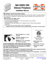
WARNING: If the information in these instructions
is not followed exactly, a fire or explosion may
result, causing property damage, personal injury
or loss of life.
MODELS:
#PRC-36 / #PRC-36-RF
‘PRINCETON’
Direct Vent Gas Fireplace
INSTALLATION AND
OPERATING MANUAL
US Patent #6004493
‚ Do not store or use gasoline or other flammable
vapors and liquids in the vicinity of this or any other
appliance.
WHAT TO DO IF YOU SMELL GAS
:
‚ Do not try to light any appliance.
‚ Do not touch electrical switches; do not use the
phone in your building.
‚ Immediately call your gas supplier from a
neighbor’s phone. Follow your gas supplier’s
instructions.
‚ If you cannot reach your gas supplier, call the fire
department.
Installation & service must be performed by a qualified
installer, service agency, or the gas supplier.
This appliance is only for use with the type(s) of gas
indicated on the rating plate and may be installed in an
aftermarket permanently located, manufactured (mobile)
home, where not prohibited by local codes. See owner’s
manual for details. This appliance is supplied with a
conversion kit.
IMPORTANT:
READ INSTRUCTIONS CAREFULLY BEFORE INSTALLATION. FAILURE TO
INSTALL THIS FIREPLACE CORRECTLY CAN CAUSE SERIOUS STRUCTURAL
AND FIRE HAZARDS AND MAY VOID YOUR WARRANTY.
www.kozyheat.com
Report No. 216-F-10-5 August 2006

Page 1
INDEX
DESCRIPTION PAGE
SAFETY REQUIREMENTS / SPECIFICATIONS ......................................................................................2-3
MINIMUM CLEARANCES ........................................................................................................4-5
TYPICAL INSTALLATION OPTIONS ................................................................................................ 5
VENTING REQUIREMENTS ......................................................................................................5-9
MINIMUM / MAXIMUM VENTING REQUIREMENTS ...............................................6
HORIZONTAL VENTING ................................................................... 6-7
TERMINATION CAP LOCATION...............................................................8
VERTICAL VENTING........................................................................9
DETERMINE LOCATION ......................................................................................................10-11
VENT SYSTEM FRAMING ..................................................................10
ROUGH-IN DIMENSIONS ...................................................................11
PREPARE THE FIREPLACE ..................................................................................................... 12
POSITION THE FIREPLACE...................................................................................................... 13
REMOVE THE GLASS ASSEMBLY ...........................................................13
DIRECT VENT CHIMNEY INSTALLATION ........................................................................................14-15
KOZY HEAT #800 SERIES FLEXIBLE TERMINATION KIT INSTALLATION ........................ 14-15
FAN INSTALLATION..........................................................................................................16-18
MODEL #PRC-36....................................................................... 16-17
MODEL #PRC-36-RF....................................................................... 18
GAS LINE SPECIFICATIONS ...................................................................................................19-20
SECURE THE MILLIVOLT BOARD ................................................................................................ 20
ADJUST COMBUSTION AIR INTAKE SHIELD - VERTICAL TERMINATIONS ONLY......................................................... 20
LOG INSTALLATION ........................................................................................................... 21
THERMOSTAT - WALL SWITCH - REMOTE CONTROL INSTALLATION (MODEL #RPC-36 ONLY) ............................................ 22
COMPLETE THE INSTALLATION ...............................................................................................23-24
MODEL #PRC-36 LIGHTING & SHUTDOWN...................................................................................25-26
MANIFOLD & INCOMING PRESSURE CHECK PROCEDURES ....................................................... 27
MODEL #PRC-36-RF LIGHTING & SHUTDOWN ...................................................................................28-29
MANIFOLD & INCOMING PRESSURE CHECK PROCEDURES ....................................................... 30
CLEANING & MAINTENANCE REQUIREMENTS .................................................................................... 31
MILLIVOLT BOARD REMOVAL / INSTALLATION ..................................................................................32-34
TROUBLE SHOOTING ........................................................................................................35-26
REPLACEMENT PARTS LISTS ................................................................................................... 37
WARRANTY POLICY .........................................................................................................38-39

Page 3
IMPORTANT:
READ THIS MANUAL BEFORE INSTALLING AND USING THIS FIREPLACE
MODEL #PRC-36 PRINCETON’ DIRECT VENT GAS FIREPLACE
This fireplace has been tested to and complies with ANSI Z21.88B-2003 CSA 2.33B-2003 “VENTED GAS FIREPLACE HEATERS”
by OMNI-Test Laboratories, Beaverton, OR. Installation must conform with local building codes or in the absence of local building
codes, with the National Fuel Gas Code, ANSI Z223.1/ NFPA 54 - Current Edition, or the Natural or Propane Installation Code, CSA
B149.1.
COMMONWEALTH OF MASSACHUSETTS
INSTALLATIONS
WARNING: This Product Must Be Installed By A Licensed
Plumber Or Gas Fitter When Installed Within The
Commonwealth of Massachusetts.
IMPORTANT: Installation of a CO detector is required in
the fireplace room.
WARNING: Do not use this fireplace if any part has been
under water. Immediately call a qualified service technician
to inspect this appliance and to replace any part of the
control system and any gas control which has been under
water.
WARNING:
DO NOT REPLACE THIS BURNER UNIT WITH ANY
OTHER SIZED BURNER. REPLACEMENT WITH AN
UNAUTHORIZED BURNER CAN RESULT IN
TEMPERATURES EXCEEDING THE LIMITS FOR THIS
FIREPLACE, AND VOID YOUR WARRANTY.
IMPORTANT: NON-COMBUSTIBLE FACING MATERIAL
MAY BE APPLIED OVER THE FACE. TO PREVENT THE
FACING MATERIAL FROM CRACKING AND FALLING
OFF DUE TO EXPANSION OF THE FACE WHEN
HEATED, DO NOT ATTACH FACING MATERIAL
DIRECTLY TO THE FACE OF THE UNIT. DO NOT
OBSTRUCT THE FLOW OF VENTILATION AIR.
CONSULT YOUR LOCAL OR NATIONAL INSTALLATION
CODES TO ASSURE THAT ADEQUATE COMBUSTION
AND VENTILATION AIR IS AVAILABLE.
INSPECT THE FIREPLACE & ALL COMPONENTS
Inspect the fireplace, vent system & all components. Contact your dealer if any parts are damaged or missing. Do not
install the fireplace with damaged, incomplete, or substitute parts.
PLANNING THE INSTALLATION
Prior to installation of this fireplace, the following must be considered:
‚ Location of fireplace.
‚ Configuration of vent system.
‚ Gas piping.
‚ Electrical wiring (if needed).
‚ Framing.
‚ Hearth height, width & depth. NOTE: A hearth is required - refer to page #4 for complete information.
‚ Materials used for finishing the fireplace.
‚ Optional accessories used.
NOTE: When the fireplace is installed directly on carpeting, tile, or other combustible materials other than wood flooring, it must
be installed on a metal or wood panel extending the full width and depth of the unit. The minimum for the support platform under
the unit is 35 7/8" wide by 21 3/8" deep.
If masonry is to be used (optional), prepare the necessary foundation for the masonry load. When masonry construction is being
used, a lintel must be used over the top of the unit to support the added weight.

Page 4
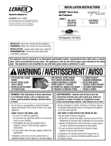
SPECIFICATIONS
Height ...................................32"
Height to top of stand-off ..................... 42"
Front width ............................ 35 7/8"
Back width............................. 24 5/8"
Depth................................. 21 3/8”
Refer to Diagrams for additional measurements.
FIGURE 1

Page 5
INSTALLATION REQUIREMENTS:
Minimum clearances from the fireplace to combustible materials:
From unit face top: 10 "
From unit left & right sides & back: 1/2"
From face sides: 1/4"
Unit bottom to flooring: 0"
Unit top to ceiling: 31"
Unit side to adjacent sidewall: 10"
Unit front: 36"
MANTEL REQUIREMENTS*:
Unit top to 10" mantel: 15" minimum*
Projection: 3/4" maximum projection allowed
at a minimum of 10" from unit top.
*Mantel height must be raised 1" for every additional 1" of depth.
See chart at right for mantel requirements. No mantel is allowed
from 0" - 15" from the top of the fireplace.
HEARTH REQUIREMENTS - Figures 2A & 2B.
When the fireplace is installed on carpet, tile or other combustible material, it must be installed on a metal or wood
panel extending the full width & depth of the fireplace. The minimum platform size is 35 7/8" wide X 21 3/8" deep.
HEARTH EXTENSIONS: A HEARTH EXTENSION IS REQUIRED AND MUST COMPLY WITH THE FOLLOWING
REQUIREMENTS:
RAISED HEARTH EXTENSION:
COMBUSTIBLE MATERIAL: The minimum hearth extension height when using combustible material is 2" high.
The maximum hearth extension depth when using combustible material is: 6" deep. Refer to Figure 2A.
NON-COMBUSTIBLE MATERIAL: The minimum hearth extension size when using non-combustible material is
2" high X 6" deep. Refer to Figure 2A.
NON-RAISED HEARTH EXTENSION: Only non-combustible material may be used if installing this fireplace without a
raised hearth. The minimum non-raised hearth extension is 36" wide by 14"
deep. Refer to Figure 2B.
Figure 2A
Figure 2B
HEARTH EXTENSION REQUIREMENTS:
Combustible material: Minimum hearth extension height: 2"
Maximum hearth extension depth: 6"
Non-combustible material required in front of the fireplace
Non-combustible material: Minimum hearth when a raised hearth is not used. Minimum hearth
extension size: 2" high x 6" deep. extension size: 36" wide x 14" deep.

Page 6
VENTING REQUIREMENTS:
THIS FIREPLACE IS APPROVED FOR USE WITH THE FOLLOWING 5" X 8" DIRECT VENT SYSTEMS: SIMPSON DURA-VENT DV-GS,
AMERI-VENT, AND SELKIRK METALBESTOS.
THIS FIREPLACE IS ALSO APPROVED FOR USE WITH THE KOZY HEAT #800 SERIES FLEXIBLE VENT SYSTEM FOR HORIZONTAL
VENTING APPLICATIONS.
THIS FIREPLACE IS DESIGNED TO BE USED WITH ANY OF THE ABOVE VENT SYSTEMS WITHOUT
THE USE OF AN ADDITIONAL
ADAPTOR.
Contact your dealer for the appropriate venting components for your specific application.
VENT SYSTEM CLEARANCES:
Dura-Vent, Ameri-Vent, or Selkirk Metalbestos chimney systems: Horizontal Sections: Top: 3"
Sides & bottom: 1"
Vertical Sections: All sides: 1"
#800 Series Flex Vent System: Top: 3"
Sides & bottom: 1"
IMPORTANT: THE KOZY HEAT WALL THIMBLE PASS-THRU, PART #800-WPT MUST BE USED ON
ALL HORIZONTAL VENT RUNS. THE MINIMUM WALL THICKNESS FOR THIS PASS-
THRU IS 4 ½" AND THE MAXIMUM WALL THICKNESS IS 8"
.
TYPICAL INSTALLATION OPTIONS:
Typical Horizontal Installation - Figure 3A Typical Vertical Installation - Figure 3B
Typical Corner
Installation - Figure 3C
Clearance to Combustible Material
diagram - Figure 3D
Refer to the vent system manufacturer’s installation manual for complete installation instructions. Installation must conform with the venting
requirements & restrictions as outlined in this manual.
IMPORTANT: Consult the local and national installation codes to ensure that adequate combustion and ventilation air is available.

Page 6
VENTING SPECIFICATIONS:
IMPORTANT: Flame height and appearance will vary depending upon venting configuration and type of fuel used.
HORIZONTAL TERMINATIONS:
IMPORTANT: The horizontal heat shield included with this fireplace must be installed when using a 45-degree elbow to
horizontally position the vent system.
Minimum: 45-degree elbow at start followed by 6" section, then termination cap.
Maximum: Option #1: 45-degree elbow at start followed by a maximum 5 ft.
Option #2: 6" section at start followed by a 45-degree elbow then maximum horizontal 10 ft.
VERTICAL TERMINATIONS: Minimum: 45-degree elbow at start followed by 2 ft.
Maximum: 45-degree elbow at start followed by a maximum 30 ft.
CORNER INSTALLATION: 45-degree elbow at start to vertically position the vent system, then a 90-degree elbow to
horizontally position the vent system, then the appropriate vent section or adjustable vent
section to accommodate the exterior wall thickness.
ELBOWS: FOR EACH ADDITIONAL ELBOW USED AFTER THE FIRST ELBOW, 3 FT. MUST BE SUBTRACTED FROM THE
MAXIMUM VENTING ALLOWED. NOTE: (2) 45-DEGREE ELBOWS MAY BE USED IN PLACE OF (1) 90-
DEGREE ELBOW.
HORIZONTAL & VERTICAL COMBINATION: 25 ft. - 10 ft. maximum horizontal / 15 ft. maximum vertical.

Page 7
MINIMUM HORIZONTAL VENTING
IMP0RTANT: THE KOZY HEAT WALL PASS-THRU, PART #800-WPT MUST BE USED ON ALL HORIZONTAL VENT
RUNS. THE MINIMUM WALL THICKNESS FOR THIS PASS-THRU IS 4 ½" AND THE MAXIMUM WALL
THICKNESS IS 8".
Minimum horizontal venting
NOTE: Horizontal Vent Heat shield must be installed when using
a 45-degree elbow to horizontally position the vent system.
Horizontal Vent
NOTE: Option #1 shown in Figure 4A. Heat Shield
A maximum horizontal run of
5 feet is allowed for this venting
configuration.
Horizontal
Termination cap
45 degree
elbow
Min. 6" pipe
Figure 4A
Minimum corner installation
NOTE: Horizontal Vent Heat shield is not used on
corner venting configurations.
Horizontal Termination cap
Min. 9" section (2" x 4" construction)
Figure 4B or the adjustable pipe to accommodate the
exterior wall thickness.
90-degree elbow
45-degree elbow

Page 8
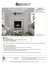
TERMINATION VENT CAP LOCATION:
This gas appliance must not be connected to a chimney flue serving another type of appliance.
GENERAL:
1. Terminations against vinyl siding must use a vinyl siding protector. Follow instructions included.
2. DO NOT RECESS TERMINATION KIT INTO OUTSIDE BUILDING MATERIALS - i.e.: brick, stone, siding, etc.. If necessary,
extend framing so that termination kit will be exposed once building materials are installed.
3. Vent termination must not be located where it will become plugged by snow or other material. The flow of combustion and
ventilation air must be not obstructed.
LOCATION CLEARANCES:
1. Above grade, veranda, porch, deck, balcony - 12". (A)
2. Operable window - 12". (B)
3. Permanently closed window* - 12" (recommended to prevent condensation on window). (C)
4. Ventilated soffit* - 24". (D)
5. Unventilated soffit* - 12". (E)
6. Outside / inside corner* - 6". (F)
7. Meter / Regulator: NOT TO BE INSTALLED ABOVE within 3 ft. horizontally from the center line of the regulator.
8. Service regulator vent outlet - 3 ft. radius.
9. Non-mechanical air supply inlet to building - 12".
10. Combustion air inlet to any other appliance - 12".
11. Mechanical air supply inlet (G) - CANADA: 6 ft. US: 3 ft. above if within 10 ft. horizontally.
NOTE: Massachusetts installations: 10 ft.
12. Above furnace exhaust or inlet - 12".
13. Above paved side-walk or paved driveway located on public property - 7 ft. (H)
NOTE: A vent cannot be located directly above a side-walk or paved driveway that is located between two single family
dwelling and serves both dwellings.
14. Under veranda, porch, deck, or balcony (must be fully opened on a min. of 2 sides) - 12". (I)
15. Between two horizontal terminations - 12".
16. Between two vertical terminations - 12". (J) - Note: May be the same height.
*Clearance must be in accordance with local installation codes & the requirements of the gas supplier.
Figure 5

Page 9
WHEN VERTICALLY TERMINATING, THE MINIMUM CHIMNEY HEIGHT ABOVE THE ROOF LINE IS
DETERMINED BY THE FOLLOWING CHART:
Roof Pitch Minimum Chimney Height Roof Pitch Minimum Chimney Height
Flat to 6/12 1 ft. 13/12 to 16/12 6 ft.
6/12 to 9/12 2 ft. 17/12 to 21/12 8 ft
10/12 to 12/12 4 ft.
CAUTION: This gas appliance must not be connected to or joined with any chimney flue
serving any other appliance.
Vertical Termination Cap
NOTE: Horizontal Vent Heat shield is not used on
vertical venting configurations.
Max. Vertical Height: 30 ft.
Figure 6A
45
o
elbow

Page 10
DETERMINE LOCATION
1. Determine the exact position of your fireplace, the width, depth and height of the hearth & hearth extension (required),
and location of the vent system termination. If possible place the fireplace in such a manner that the vent termination
will be placed between two studs so additional framing is not necessary.
HEARTH REQUIREMENTS: When the fireplace is installed on carpet, tile or other combustible material, it must be
installed on a metal or wood panel extending the full width & depth of the fireplace.
The minimum platform size is 35 7/8" wide X 21 3/8" deep.
HEARTH EXTENSIONS: A HEARTH EXTENSION IS REQUIRED AND MUST COMPLY WITH THE REQUIREMENTS ON
PAGE #4 OF THIS INSTALLATION MANUAL.
If masonry is to be used (optional), prepare the necessary foundation for the masonry load. When masonry construction
is being used, a lintel must be used over the top of the fireplace to support the added weight.
IMPORTANT - Vent cap location must be in compliance with the guidelines on page #8 of this manual.
2. HORIZONTAL TERMINATIONS:
IMPORTANT: The horizontal vent heat shield must be installed when using a 45-degree elbow to horizontally position
the vent system or when using the #800 series Kozy Heat flexible vent system for horizontal terminations. Refer to page
#12 of this manual for instruction on attaching the horizontal vent heat shield.
Frame a 12 1/2" high (H) x 10 7/8" wide (W) opening on
the exterior wall for the chimney termination.
This opening size includes the required 3" clearance at
the top and 1" clearance at the sides and bottom of
approved rigid vent systems and the Kozy Heat #800
series flexible vent system.
To achieve the minimum horizontal venting
requirement OPTION #1 for RIGID PIPE
APPLICATIONS, a minimum of 34 3/8" (A) to the top
of the vent pipe and 37 3/8" (B) to the top of the
framed opening from the floor or hearth the fireplace
is setting on is required. See Figure 7A.
To achieve the minimum horizontal venting
requirement OPTION #2 for RIGID PIPE
APPLICATIONS, a minimum of 37 1/2" (A) to the top
of the vent pipe and 40 1/2" (B) to the top of the
framed opening from the floor or hearth the fireplace
is setting on is required. See Figure 7A.
To achieve the minimum venting requirement
for
FLEX VENT APPLICATIONS
, a minimum of 37 7/8"
(A) to the top of the vent pipe and 40 7/8" (B) to the
top of the framed opening from the floor or hearth
the fireplace is setting on is required. See Figure 7A.
CORNER INSTALLATIONS:
To achieve the minimum corner venting requirements
for RIGID PIPE APPLICATIONS, a minimum of 45" (A)
to the top of the vent pipe and 48" (B) to the top of
framed opening from the floor or hearth the fireplace
is setting on is required.
Figure 7A

Page 11
3. VERTICAL TERMINATIONS: Follow vent pipe manufacturer’s installation instructions for vertical terminations. A
minimum 1" clearance on all sides of vertical vent pipe sections must be maintained.
The horizontal vent heat shield is not used for vertical venting configurations.
CAUTION: COLD AIR TRANSFER AREA. THE SURROUNDING CHASE OF THE FIREPLACE MUST COMPLY WITH ALL CLEARANCES AS
OUTLINED IN THIS MANUAL AND BE CONSTRUCTED IN COMPLIANCE WITH LOCAL BUILDING CODES. OUTSIDE WALLS SHOULD BE
INSULATED TO PREVENT COLD AIR FROM ENTERING THE ROOM.
NOTE: Due to high temperatures, this unit should be located out of traffic areas and away from furniture and draperies.
4. Build the hearth and hearth extension. Refer to page #4 for complete information.
5. Rough in the wall enclosure. Figure 7B.
IMPORTANT: Framing dimensions should allow for wall
covering thickness and fireplace facing materials. Adjust rough
opening size as necessary to maintain at least the minimum
clearance requirements.
MINIMUM FINISHED
OPENING DIMENSIONS (Wall covering /
facing materials included):
HORIZONTAL TERMINATIONS:
42" high x 36 3/8" wide x 21 7/8" deep*
*½" clearance at the back & sides of the fireplace must be
maintained for horizontal terminations. See Figure 3A,
page #5.
VERTICAL TERMINATIONS:
42" high x 36 3/8" wide x 23 7/8" deep*
*2½" clearance at the back to maintain required vent
system clearance and ½" at the sides of the fireplace must
be maintained for vertical terminations. See Figure 3B,
page #5.
Figure 7B
Minimum horizontal termination, Option #1,
shown above.
Figure 7C
NOTE: Provide adequate clearance in front of the fireplace to access the control valve, install and attach gas line, install a fan, etc..
Do not obstruct the upper and lower convection air passage areas to allow proper ventilation air around the unit. Room air enters
through the lower passage, is heated and exits at the upper passage. Blocking these passages may result in overheating the
fireplace creating a potentially hazardous situation.

Page 12
PREPARE THE FIREPLACE
STAND-OFF ASSEMBLY & INSTALLATION
1. The top stand-off brackets must be formed and correctly
positioned prior to positioning the fireplace into the framed
opening. Figure 8A.
The top stand-off brackets are attached to the top of the
fireplace in a flat state when the fireplace is shipped.
2. Remove the screws securing each stand-off bracket and
remove from the fireplace.
3. Remove the remaining (2) sets of screws under the stand-off
brackets and set aside.
4. Form each stand-off as shown in Figure 8B.
Figure 8B
5. Re-attach the stand-off brackets to the top of the fireplace
using the screws removed in steps #2-#3 above. Figure 8C.
Figure 8A
Figure 8C
HORIZONTAL VENT APPLICATIONS:
ATTACH THE HORIZONTAL VENT HEAT SHIELD:
1. Loosen, but do not remove the center three screws at
the back of the fireplace as shown in Figure 9A.
Figure 9A
2. Slide the (3) slots on the horizontal vent heat shield under the
screws. Re-tighten the screws to secure in place. Refer to
Figure 9B.
Figure 9B

Page 13
VERTICAL VENT APPLICATIONS
This fireplace is approved for use with the Simpson Dura-Vent, Ameri-Vent and the Selkirk Metalbestos 5" x 8" direct vent systems for
vertical vent applications. There is no additional adaptor necessary to begin installing the chimney components.
POSITION THE FIREPLACE
1. Place the fireplace into position. Figure 10.
NOTE: Shown in horizontal vent
configuration
2. REMOVE THE GLASS ASSEMBLY.
See Figure 11.
A. Locate the spring-loaded handles securing the
glass assembly at the top & bottom of the firebox.
CAUTION: TO PREVENT THE GLASS ASSEMBLY FROM
FALLING FROM THE FIREPLACE AND BECOMING
DAMAGED, FOLLOW THESE DIRECTIONS EXACTLY WHEN
REMOVING THE GLASS ASSEMBLY.
B. Pull the handles out, then ‘down’ to release the
glass assembly at the bottom.
C. Pull the handles out, then ‘up’ to release the glass
assembly at the top.
D. Lift the glass assembly off from the front of the
fireplace and set aside where it will not be broken.
E. Remove the log package from the firebox and set
aside.
Figure 10
Figure 11

Page 14
VENT SYSTEM INSTALLATION:
Install the vent system components for your specific venting configuration. Follow the vent system manufacturer’s installation
instructions in conjunction with the venting requirements in this installation manual.
HORIZONTAL & VERTICAL TERMINATIONS:
All firestops, support brackets, etc. must be used as specified by the vent system manufacturer.
All clearances and venting requirements as specified in this manual must be followed.
HORIZONTAL TERMINATIONS:
IMPORTANT: The Kozy Heat wall pass-thru, part #800-WPT, must be used on all horizontal vent applications regardless of
which vent system you are using.
INSTALLATION OF #800 SERIES DIRECT VENT TERMINATION KIT(S)
IMPORTANT: The flex pipe is permanently attached to the exterior plate. DO NOT ATTACH the #844 or #845 termination kit to the fireplace (or
extension kit) until it has passed through the wall or roof. The termination plates should all be installed on the exterior of the outside wall.
HORIZONTAL TERMINATIONS:
IF TERMINATING AGAINST VINYL SIDING, A VINYL SIDING PROTECTOR, INCLUDED WITH THE #844 and #845 DIRECT VENT KITS,
MUST BE USED. FOLLOW INSTRUCTIONS INCLUDED.
CAUTION: This gas appliance must not be connected to a chimney flue serving another type of appliance.
1. If your vent system application is 8' or less from the top of the fireplace and doesn’t require an extension kit, proceed to step #7.
2. If your vent system application will require one or more extension kits (part #846), proceed with the following steps. Each #846
extension kit contains enough 5" and 8" flexible aluminum to extend the chimney an additional 6'.
3. Gently stretch the 5" & 8" flexible aluminum pipes on the termination kit (#844 or #845) and on each extension kit, if used, the
length required so when all the sections are connected together, the vent system length for your installation is attained.
IMPORTANT: DO NOT STRETCH THE EXTENSION KIT BEYOND 6'. DO NOT STRETCH BEYOND WHAT IS REQUIRED - IT IS VERY
DIFFICULT TO RECOMPRESS THE FLEX PIPES ONCE STRETCHED.
4. Using your extension kit pieces, place a bead of sealant outside the 5" flex pipe collar (C) - the end with the EXTERNAL lip - and
slide it inside the 5" pipe on top of the fireplace (D). Secure with 3 evenly spaced screws.
5. Place a bead of sealant inside the 8" flex pipe collar (E) - the end with the INTERNAL lip - and slide it over the 8" pipe on top of the
fireplace (F). Secure with 3 evenly spaced screws.

Page 15
Minimum venting requirements: A minimum of 37 7/8"
to the top of the vent pipe and 40 7/8" to the top of the
framed opening from the floor or hearth the fireplace is
setting on is required.
Refer to pages #5 - #10 for complete venting
requirements & restrictions.
FIGURE 13
6. If additional extension kits are being used, repeat steps 4 and 5, placing the 5" & 8" pipes onto the previous extension kit.
Refer to Figure 13:
7. A 800-WPT wall pass-thru must be used for horizontal runs that pass through either interior or exterior walls. Install the 800-WPT
wall pass-thru on both sides of the 12 1/2" high X 10 7/8" wide square opening and secure with nails or screws.
NOTE: Attachment brackets are included with the termination kit. These optional brackets should be screwed or nailed (screws not
provided) onto the top and bottom of the 12 1/2" high X 10 7/8" wide square opening, on the exterior of the house. The termination plates
then fit between these brackets, and using the screws provided, screw the brackets to the termination kit box (A). Attach the vinyl siding
protector (G).
8. Apply a liberal bead of exterior sealant around the outer edge of the plate (A), and place the assembly through the square opening
in the exterior wall. Place screws through the four slots (B) securing it in place.
9. Gently pull the 5" & 8" flexible aluminum down to the top of the extension kit, or the top of the fireplace if no extension kits were
used.
10. Place a bead of sealant outside the 5" flex pipe collar (C) and slide it into the 5" pipe on the extension kit or top of the fireplace (D).
Secure with 3 evenly spaced screws.
NOTE: This connection is very difficult to remove without damaging the collars once installed.
11. Place a bead of sealant inside the 8" flex pipe collar (E) and slide it over the 8" pipe on the extension kit or top of the fireplace (F).
Secure with 3 evenly spaced screws.
NOTE: This connection is very difficult to remove without damaging the collars once installed.
12. OPTIONAL: Place insulation between the 8" pipe and the wall studs.

Page 16
MODEL #PRC-36 ONLY: OPTIONAL FAN INSTALLATION INSTRUCTIONS
INSTALLATION OF THIS FAN SHOULD BE DONE ONLY BY A QUALIFIED INSTALLER
IMPORTANT: If a fan is going to be installed, it is easier to complete before the millivolt board is connected to the gas line.
The wiring must be done prior to enclosing the sides of the unit. An electrical box & romex connector are pre-installed
on a removable panel on the right side of the fireplace. A receptacle / speed control assembly and (3) wire nuts are
included in the fireplace components packet.
This optional fan kit, part #TRF-028, includes:
Right & left fan assemblies with thermostatic control switch
Components package: Installation instructions
NOTE: Code approved line voltage wiring 14 gauge or better must be used when wiring this assembly. Refer to your local
electrical codes for specific requirements in your area.
WARNING: This appliance is equipped with a three-prong (grounding) plug for protection against shock hazard and should be plugged
directly into a properly grounded three-prong receptacle. Do not cut or remove the grounding prong from this plug.
Figure 14A

Page 17
INSTALLATION INSTRUCTIONS
THE FOLLOWING COMPONENTS MUST BE REMOVED FROM THE
FIREPLACE PRIOR TO INSTALLATION OF THIS FAN. REFER TO
THE CORRESPONDING INSTALLATION MANUAL PAGES FOR
ASSISTANCE IF NECESSARY.
1. Upper hood, upper louver & lower grill, if installed. Refer to
page #24 if necessary.
2. Glass assembly. Refer to page #13 if necessary.
Note: Millivolt board has been removed for clarity. It is not
necessary to remove the millivolt board to install this
optional fan kit.
INSTALL THE FANS:
1. Slide the left & right fans through the lower grill opening (left
side of the valve) and push all the way to the fireplace back.
2. Slide the left fan assembly to the left until it stops and slide the
right fan assembly to the right until it stops. NOTE: The fans
will be behind the legs. Figure 14B.
NOTE: Each fan bracket is held in position by a magnetic strip
attached to the bottom of each bracket. The mounting studs
are not used when installing this fan assembly.
3. Connect the fan wiring by inserting the red connectors on the
right fan wires onto the terminals on the left fan assembly. It
does not matter which connector is on each terminal. Figure
14C.
4. Remove the (2) screws securing the removable access panel
(with electrical box & romex connector installed) from the right
side of the fireplace.
6. Insert 115V wiring (with ground) through the romex connector
and wire to the speed control / receptacle assembly matching
the black (hot) white (neutral) and green (ground) wire to the
corresponding wire on the speed control / receptacle assembly.
NOTE: (3) wire nuts are included in the fireplace components
packet.
7. Secure the speed control / receptacle assembly into the
electrical box with the (2) screws provided. Figure 14D.
8. Replace the electrical access panel and secure with the (2)
screws removed.
9. Place the thermostatic control switch on the bottom of the
firebox. Figure 14D.
10. Plug cord into receptacle in the electrical box. Figure 14D.
11. Turn on/off speed control counter-clockwise until it ‘clicks’.
This is the ‘OFF’ position.
12. Turn the speed control ‘ON’ by turning the knob clockwise past
the ‘click’ - this is the highest setting.
13. Replace the glass assembly. Refer to page #24 if necessary.
14. Replace the lower grill, upper louver & upper hood. Refer to
page #24 if necessary.
NOTE: This appliance must be electrically grounded and connected in
accordance with local codes, or in the absence of local codes, with the National
Electrical Code, ANSI/NFPA 70-Current edition, or the Canadian Electrical Code,
CSA C22.1.
Figure 14B
Connect fan
wiring
Figure 14C
Figure 14D
THERMOSTATIC CONTROL SWITCH POSITION: Prior to adjusting the
temperature control switch, unplug the 3-prong plug on the fan cord from the
receptacle. Adjust the position of the temperature control switch to a warmer
location under the firebox to turn the fan ‘ON’ sooner or move it to a cooler
location under the firebox to turn the fan ‘ON’ later. The fan will turn on when the
sensor in the temperature control switch reaches 110
o
F and will turn ‘OFF’ when
the sensors reach 90
o
F. After adjustment, plug the 3-prong plug on the fan cord
into the receptacle.
NOTE: The fan will not operate unless the speed control has been turned
‘ON’ and sufficient heat has been applied to the thermostatic control
switch. The fan will turn ‘ON’ and ‘OFF’ automatically when the fireplace
heats and cools. Adjust fan to desired speed while it is running.
Slide to the left.
Slide to the right.
Speed Control /
receptacle assembly
Thermostatic
Control Switch

Page 18
MODEL #PRC-36-RF ONLY: FAN INSTRUCTIONS
INSTALLATION OF THIS FAN WIRING SHOULD BE DONE ONLY BY A QUALIFIED INSTALLER
IMPORTANT: A fan assembly is pre-installed and wired to the RF gas valve in the PRC-36-RF models.
The wiring must be done prior to enclosing the sides of the unit. An electrical box & romex connector are pre-installed
on a removable panel on the right side of the fireplace. A duplex receptacle and cover is included in the fireplace
components packet.
NOTE: Code approved line voltage wiring 14 gauge or better must be used when wiring this assembly. Refer to your local
electrical codes for specific requirements in your area.
WARNING: This appliance is equipped with a three-prong (grounding) plug for protection against shock hazard and should be plugged
directly into a properly grounded three-prong receptacle. Do not cut or remove the grounding prong from this plug.
Figure 15
1. Remove the (2) screws securing the removable access panel (with electrical box & romex connector installed) from the right side
of the fireplace.
2. Insert 115V wiring (with ground) through the romex connector and wire to the duplex receptacle. Secure the duplex receptacle to
the electrical box.
3. Place the cover on the electrical box and secure with screw.
4. Re-install the electrical access panel and secure with the (2) screws removed.
5. Plug the 3-prong plug on the fan cord into the receptacle.
6. Upon complete installation of this fireplace, follow the lighting & shutdown instructions at the back of this manual as well as the
instructions included in the remote transmitter for complete fan operation guidelines.

Page 19
RUN THE GAS LINE.
CAUTION: Installation of the gas line must only be done by a qualified person in accordance with local building codes.
GAS CONVERSIONS - If a gas conversion to LP GAS is necessary, the appropriate gas conversion kit, #H5271-L for Model
#PRC-36 and #H5271L-RF for Model #PRC-36-RF, is included in the fireplace components packet.
The conversion shall be carried out in accordance with the requirements of the provincial authorities having jurisdiction and in
accordance with the requirements of the ANSI Z223.1 installation code.
NOTE: This fireplace is equipped with a 3/8" x 18” long flexible gas connector and manual shut off valve.
NOTE: The gas line should be run to the point of connection where the shut-off valve and flexible gas line will connect.
CAUTION: The manual shut-off valve or flexible gas tubing must not extend outside of the unit cavity. See the WARNING
label affixed to the flexible tubing for additional installation instructions and warnings.
NATURAL GAS:
The minimum inlet gas supply pressure: 5.0 inches W.C. ( 7.0 inches W.C. recommended)
The maximum inlet gas supply pressure: 10.5 inches W.C.
Manifold pressure: 3.5 inches W.C.
Manifold pressure (lo setting): 1.7 inches W.C.
Orifices sizes: #37 & #55 Input: 35,000 BTU/hr. Efficiency: 68.33% AFUE: 67.69% P-4 AFE: 54.77%
Minimum input: 22,500 BTU/hr.
LP GAS
:
The minimum inlet gas supply pressure: 11.0 inches W.C. (recommended)
The maximum inlet gas supply pressure: 13.0 inches W.C.
Manifold Pressure: 10.0 inches W.C.
Manifold Pressure (lo setting): 6.5 inches W.C.
Orifices size: #52 & #71 Input: 34,800 BTU/hr. Efficiency: 71.81% AFUE: 71.20% P-4 AFE: 58.79%
Minimum input: 25,500 BTU/hr.
This fireplace is equipped for use at altitudes of 0-2,000 ft. in the U.S. and 0-4,500 ft. in Canada.
IMPORTANT: The efficiency rating of this appliance is a product thermal efficiency rating determined under
continuous operating conditions and was determined independently of any installed system.
NOTE: For high altitude installations consult the local gas distributor or the authority having jurisdiction for proper rating methods.
1. Run the gas line. Gas line holes are positioned on both sides of the fireplace for gas line connection. An accessible shut
off valve (included) must be installed up stream from the regulator.
NOTE: Do not run the incoming gas line in a manner that would obstruct the operation of the fan, if used.
2 . This fireplace is designed to accept either a 3/8" or 1/2" gas line approved for gas appliances. Consult local building codes
to properly size the gas supply line leading to a 3/8" reduction.
/