Page is loading ...

HUSSONG MANUFACTURING CO., INC.
INSTALLATION AND
OPERATION MANUAL
ͷ Do not store or use gasoline or other
ammable vapors and liquids in the vicinity
of this or any other appliance.
ͷ WHAT TO DO IF YOU SMELL GAS
• Do not try to light any appliance.
• Do not touch any electrical switch; do
not use any phone in your building.
• Leave the building immediately.
• Immediately call your gas supplier from
a neighbor’s phone. Follow the gas
supplier’s instructions.
• If you cannot reach your gas supplier,
call the re department.
ͷ Installation and service must be performed
by a qualied installer, service agency or
the gas supplier.
WARNING:
FIRE OR EXPLOSION HAZARD
Failure to follow safety warnings exactly
could result in serious injury, death, or
property damage.
This appliance may be installed in
an aftermarket, permanently located,
manufactured home (USA only) or mobile
home, where not prohibited by local codes.
This appliance is only for use with the type
of gas indicated on the rating plate. This
appliance is not convertible for use with other
gases, unless a certied kit is used.
INSTALLER: Leave this manual with the appliance.
CONSUMER: Retain this manual for future reference.
English and French installation manuals are available through your
local dealer. Visit our website www.kozyheat.com.
Les manuels d’installation en français et en anglais sont disponibles
chez votre détaillant local. Visitez
www.kozyheat.com
.
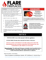
DANGER
HOT GLASS WILL
CAUSE BURNS
DO NOT TOUCH GLASS
UNTIL COOLED
NEVER ALLOW CHILDREN
TO TOUCH GLASS
A barrier designed to reduce the risk of burns
from the hot viewing glass is provided with this
appliance and shall be installed for the protection
of children and other at-risk individuals.
ROOSEVELT 34 BW
Model #RVT-34-BW
Direct Vent Gas Fireplace Insert
Hussong Mfg. Co., Inc.
RVT-34-BW Report No: 19-541
Rev. 2, November 2019
Starting Serial Number: 20 601900 17


#RVT-34-BW R.2 November 2019 Hussong Mfg. Co., Inc. • Kozy Heat Fireplaces 3
Read this manual before installing or operating this appliance.
Please retain this owner’s manual for future reference.
Jim Hussong
President
Dudley Hussong
Board Chairman
Homeowner Reference Information
We recommend you record the following information:
Model Name: ____________________________________________
Serial Number: ___________________________________________
Dealership Purchased from: ________________________________
Date purchased/installed: __________________________________
Location of replace: ______________________________________
Dealer phone: ___________________________________________
Notes: ______________________________________________________________________________________________________________
____________________________________________________________________________________________________________________
____________________________________________________________________________________________________________________
____________________________________________________________________________________________________________________
Hussong Manufacting welcomes you as a new own of a Kozy Heat gas feplace. Kozy Heat
products e designed with supi components and matials, assembled with ce by ained
crasmen who take pride in the wk. To ense you eceive a quality product, the bn and valve
assembly e 100 pcent test-fed, and the complete feplace is thoughly inspected befe packaging.
O commitment to quality and custom satisfaction has emained the same f ov 40 yes. We
o a complete line of gas and wood feplaces, along with stylish accessies to complement any dec.
Adding a feplace is one of the best ways to increase the value of yo home, and we e proud to o
a netwk of deals throughout the couny to help make yo expience evything you imagine. We
pride oselves in being dedicated not only to functionality and eliability, but also custom safety.
We o o continual suppt and guidance to help you achieve the maximum benet and enjoyment
om yo Kozy Heat gas feplace.
CON GRAT ULAT ION S!


#RVT-34-BW R.2 November 2019 Hussong Mfg. Co., Inc. • Kozy Heat Fireplaces TABLE OF CONTENTS 5
TABLE OF CONTENTS
TABLE OF CONTENTS .....................................................................5
1.0 INTRODUCTION ......................................................................7
1.1 Appliance Certication ............................................................................. 7
1.2 California Proposition 65 Warning ........................................................ 7
1.3 Requirements for the Commonwealth of Massachusetts ............ 7
2.0 SPECIFICATIONS .....................................................................8
2.1 Heating Specications .............................................................................. 8
2.2 Electrical Specications ............................................................................ 8
2.3 Appliance Dimensions .............................................................................. 9
2.4 Part Assembly Overview .......................................................................... 10
2.5 Safety Barrier Dimensions ........................................................................ 11
3.0 EXISTING FIREPLACE REQUIREMENTS .................................12
3.1 Appliance Placement Considerations ................................................. 12
3.2 Existing Fireplace Specications ........................................................... 12
4.0 TERMINATION LOCATION ...................................................... 14
4.1 Chimney Vent Termination Clearances ............................................... 14
4.2 Co-linear to Co-axial Vent Terminations .............................................14
5.0 INSTALLATION PREPARATION ...............................................15
5.1 Inspect and Clean Existing Chimney ................................................... 15
5.2 Flue Damper ................................................................................................. 15
5.3 Gas Line .......................................................................................................... 15
5.4 Electrical Wiring ........................................................................................... 15
5.5 Fireplace Conversion ................................................................................ 15
6.0 INSTALLATION ........................................................................16
6.1 Approved Vent Systems ............................................................................ 16
6.2 Kozy Heat #816 and #816-CAP...............................................................16
6.3 Co-linear to Co-axial Combined Venting ............................................ 17
6.4 Remove Vent Adapter ............................................................................... 18
6.5 Run Vent System.......................................................................................... 18
6.6 Connect Vent Pipe to Vent Adapter ...................................................... 19
6.7 Place and Secure Appliance ....................................................................19
6.8 Outdoor Covered Fireplace Installation .............................................. 20
7.0 GAS LINE CONNECTION .........................................................22
7.1 Gas Conversion (sold separately) .......................................................... 22
7.2 Gas Line Installation ................................................................................... 22
8.0 FACING AND FINISHING .........................................................23
8.1 Facing and Finishing Requirements ..................................................... 23
8.2 Shroud Installation ..................................................................................... 25
8.3 Safety Barrier Installation ......................................................................... 25
9.0 GAS FIREPLACE INSERT SETUP .............................................26
9.1 Glass Assembly ............................................................................................ 26
9.2 Light Kit .......................................................................................................... 26
9.3 Panel Installation .........................................................................................27
9.4 #RT34B-501 Log Set Installation ............................................................ 28
9.5 Control Board Removal and Installation ............................................. 29
10.0 ELECTRICAL INFORMATION ................................................ 30
10.1 Electrical Specications .......................................................................... 30
10.2 Wiring Requirements .............................................................................. 30
11.0 OPERATING INSTRUCTIONS ................................................ 31
11.1 Setup Proame 2 IFC Module .............................................................. 32
11.2 Initialize the Control System................................................................. 32
11.3 Reset the System for Manual Operation .......................................... 32
11.4 Automatic Safety Restart ....................................................................... 32
11.5 Backup Battery Operation .................................................................... 32
11.6 Control System 7 Day Timeout ............................................................ 32
11.7 IFC Module Ignition Sequence ............................................................ 33
11.8 Additional Diagnostic Information .................................................... 33
11.9 Remote Control Operation .................................................................. 34
12.0 ADJUSTMENT ........................................................................37
12.1 Pressure Testing ........................................................................................ 37
12.2 Burner Flame Adjustments ................................................................... 38
13.0 TROUBLESHOOTING.............................................................39
14.0 MAINTENANCE......................................................................41
14.1 Firebox .......................................................................................................... 41
14.2 Fan ................................................................................................................. 41
14.3 Vent System ................................................................................................ 41
14.4 Glass Assembly .......................................................................................... 41
14.5 Burner and Pilot System ........................................................................ 42
15.0 REPLACEMENT PARTS LIST..................................................43
LIMITED LIFETIME WARRANTY ....................................................44


#RVT-34-BW R.2 November 2019 Hussong Mfg. Co., Inc. • Kozy Heat Fireplaces INTRODUCTION 7
1.0 INTRODUCTION
1.1 Appliance Certication
Laboratory: PFS in Cottage Grove, Wisconsin
Standards:
ANSI Z21.88-2017/CSA 2.33-2017, Vented Gas Fireplace Heaters
CSA 2.17 - 2017, Gas-Fired Appliances for Use at High Altitudes
This installation must conform with local codes, or in the absence of
local codes, with the National Fuel Gas Code, ANSI Z223.1/NFPA 54, or
the Natural Gas and Propane Installation Code, CSA B149.1.
1.2 California Proposition 65 Warning
WARNING: This product can expose you to chemicals including
Carbon Monoxide, that is an externally vented by-product of fuel
combustion, which is [are] known to the State of California to cause
birth defects or other reproductive harm. For more information, visit
www.P65Warnings.ca.gov.
1.3 Requirements for the
Commonwealth of Massachusetts
The following requirements reference various Massachusetts and
national codes not contained in this manual.
For all sidewall horizontally vented gas fueled equipment installed
in every dwelling, building or structure used in whole or in part for
residential purposes, including those owned or operated by the
Commonwealth and where the side wall exhaust vent termination
is less than (7) feet above nished grade in the area of the venting,
including but not limited to decks and porches, the following
requirements shall be satised:
1.3.1 Installation of Carbon Monoxide Detectors
At time of installation of side wall horizontally vented gas fueled
equipment, the installing plumber or gas-tter shall observe that
a hard wired carbon monoxide detector with an alarm and battery
back-up is installed on the oor level where the gas equipment is
to be installed. In addition, the installing plumber or gas-tter shall
observe that a battery operated or hard wired carbon monoxide
detector is installed on each additional level of the dwelling, building
or structure served by the side wall horizontal vented gas fueled
equipment. It shall be the responsibility of the property owner
to secure the services of qualied licensed professionals for the
installation of hard wired carbon monoxide detectors.
In the event that the side wall horizontally vented gas fueled
equipment is installed in a crawl space or attic, the hard wired carbon
monoxide detector with alarm and battery back-up may be installed
on the next adjacent oor level. In the event that the requirements
of this subdivision can not be met at the time of completion of
installation, the owner shall have a period of thirty (30) days to
comply with the above requirements; provided, however, that during
said thirty (30) day period, a battery operated carbon monoxide
detector with an alarm shall be installed.
1.3.2 Approved Carbon Monoxide Detectors
Each carbon monoxide detector as required in accordance with the
above provisions shall comply with NFPA 720 and be ANSI/UL 2034
listed and IAS certied.
1.3.3 Signage
A metal or plastic identication plate shall be permanently mounted
to the exterior of the building at a minimum of eight (8) feet
above grade directly in line with the exhaust vent terminal for the
horizontally vented gas fueled heating appliance or equipment. The
sign shall read, in print no less the one-half inch (½) in size, “GAS VENT
DIRECTLY BELOW. KEEP CLEAR OF ALL OBSTRUCTIONS”.
1.3.4 Inspection
The state or local gas inspector of the side wall horizontally vented
gas fueled equipment shall not approve the installation unless, upon
inspection, the inspector observes carbon monoxide detectors and
signage installed in accordance with the provisions of 248 CMR 5.08
(2) (a) 1 through 4.
1.3.5 Exemptions
The following equipment is exempt from 248 CMR 5.08 (2) (a) 1
through 4: The equipment listed in Chapter 10 entitled “Equipment
Not Required To Be Vented” in the most current edition of NFPA 54 as
adopted by the Board; and Product Approved side wall horizontally
vented gas fueled equipment installed in a room or structure separate
from the dwelling, building or structure used in whole or in part for
residential purposes.
1.3.6 Manufacturer Requirements
1.3.6.1 Gas Equipment Venting System Provided
When the manufacturer of Product Approved side wall horizontally
vented gas equipment provides a venting system design or venting
system components with the equipment, the instructions provided
by the manufacturer for installation of the equipment and the
venting system shall include:
• Detailed instructions for the installation of the venting system
design or the venting system components; and
• A complete parts list for the venting system design or venting
system.
1.3.7 Gas Equipment Venting
System NOT Provided
When the manufacturer of Product Approved side wall horizontally
vented gas equipment does not provide the parts for venting the
ue gases, but identies “special venting systems”, the following
requirements shall be satised by the manufacturer:
• The referenced “special venting systems” instructions shall
be included with the appliance or equipment installation
instructions and;
• The “special venting systems” shall be Product Approved by the
Board, and the instructions for that system shall include a parts
list and detailed installation instructions.
A copy of all installation instructions for all Product Approved
side wall horizontally vented gas fueled equipment, all venting
instructions, all parts lists for venting instructions, and/or all venting
design instructions shall remain with the appliance or equipment at
the completion of the installation.

8 SPECIFICATIONS Hussong Mfg. Co., Inc. • Kozy Heat Fireplaces #RVT-34-BW R.2 November 2019
2.0 SPECIFICATIONS
2.1 Heating Specications
Natural Gas Propane
Maximum
Input Rating
40,000 Btu/h
11.72 kW
40,000 Btu/h
11.72 kW
Minimum
Input Rating
10,000 Btu/h
2.9 kW
10,000 Btu/h
2.9 kW
Manifold Pressure
(High)
3.8” WC
(0.95 kPa)
11” WC
(2.74 kPa)
Manifold Pressure
(Low)
1.1” WC
(0.27 kPa)
2.9” WC
(0.72 kPa)
Orice Size (DMS) FRONT: #46
BACK: #44
FRONT: #56
BACK: #54
2.1.1 Altitude Adjustment
This appliance may be installed at higher altitudes. Please refer to
National Fuel Gas Code ANSI Z223.1/NFPA 54, CSA-B149.1 Natural
Gas and Propane Installation Code, local authorities, or codes having
jurisdiction in you area regarding derate guidelines.
2.1.1.1 US Installations
Refer to the American Gas Association guidelines for the gas designed
appliances derating method. For elevations above 2,000’ (610m),
input ratings are to be reduced by 4% for each 1,000’ (305m) above
sea level.
2.1.1.2 Canadian Installations
When the appliance is installed at elevations above 4,500’ (1,372m),
the certied high altitude rating shall be reduced at the rate of 4% for
each additional 1,000’ (305m).
2.2 Electrical Specications
• The junction box in this appliance requires 120VAC, 60Hz, and 6
Amps.
• Verify the household breaker is shut o prior to working on any
electrical lines.
• The AC power supply to this appliance must be hot at all times
and shall not have a switch installed in it.

#RVT-34-BW R.2 November 2019 Hussong Mfg. Co., Inc. • Kozy Heat Fireplaces SPECIFICATIONS 9
2.3 Appliance Dimensions
Figure 2.1, Appliance Dimensions
16⁄”
(415mm)
24”
(609mm)
12”
(304mm)
4
⁄”
(110mm)
21
⁄”
(537mm)
22
¼”
(564mm)
33
⁄”
(860mm)
23
¾”
(603mm)
30
⁄”
(779mm)
1⁄”
(34mm)
14
⁄”
(362mm)
3
½”
(89mm)
1
⁄”
(28mm)
GAS LINE HOLE
ELECTRICAL
ACCESS
TOP VIEW
LEFT SIDE FRONT VIEW RIGHT SIDE

10 SPECIFICATIONS Hussong Mfg. Co., Inc. • Kozy Heat Fireplaces #RVT-34-BW R.2 November 2019
2.4 Part Assembly Overview
WARNING: Failure to position these parts in accordance with these
diagrams, or failure to use only specied approved parts with this
appliance, may result in property damage or personal injury.
Figure 2.2, Proper Positioning of Appliance
Table 2.1, Field-Assembled Parts
A
Fireplace insert
E
Front burner assembly
B
Glass frame assembly
F
Back burner assembly
C
Ember media tray and log rack
G
Co-linear vent adapter
D
Control board assembly H Fan Kit
A
B
C
D
E
F
G
H

#RVT-34-BW R.2 November 2019 Hussong Mfg. Co., Inc. • Kozy Heat Fireplaces SPECIFICATIONS 11
2.5 Safety Barrier Dimensions
WARNING: A barrier designed to reduce the risk of burns from the hot
viewing glass is provided with this appliance and shall be installed for
the protection of children and other at-risk individuals.
If the barrier becomes damaged, the barrier shall be replaced with
Hussong Mfg.’s barriers for this appliance.
IMPORTANT: Consider the height of hearth nish material when
building a replace platform. Proper installation of safety barriers
require the bottom of the replace to be level with nished hearth.
See section 8.3 Safety Barrier Installation on page 25 for installation
and removal of safety barriers.
35”
(889mm)
24
⁄”
(626mm)
34
⁄”
(866mm)
24
½”
(622mm)
26
½”
(673mm)
35
½”
(901mm)
25”
(635mm)
35”
(889mm)
24
⁄”
(626mm)
34
⁄”
(866mm)
24
½”
(622mm)
RT34A-MSF RT34A-FPDSF
RT34-PSF RT34-RSF
RT34-FSF

12 EXISTING FIREPLACE REQUIREMENTS Hussong Mfg. Co., Inc. • Kozy Heat Fireplaces #RVT-34-BW R.2 November 2019
3.0 EXISTING FIREPLACE REQUIREMENTS
3.1 Appliance Placement Considerations
WARNING: Due to high surface temperatures, the replace insert
should be located out of trac and away from furniture and draperies.
• This replace must be installed on a level surface capable of
supporting the replace insert and venting.
• This replace insert may be installed in a bedroom.
• Please be aware of the large amount of heat this replace insert
will produce when determining a location.
3.2 Existing Fireplace Specications
IMPORTANT: Adequate accessibility clearances for servicing and
proper operation must be maintained.
• Any smoke shelves, shields, and baes may be removed if
attached by mechanical fasteners. If necessary, remove rebrick
to obtain at least the minimum opening requirements.
• Cutting of any sheet metal parts of the existing replace is
prohibited.
• A gas line must be able to be installed to the replace insert.
Please refer to Figure 2.1 on page 9. The gas line access hole
is located on the left side of the insert.
• If the metal oor is removed, the insert must be placed directly
on metal base of metal replace using the Kozy Heat Floor
Protector Kit (#RT34-FLP). The provided leveling bolts with
the replace must be installed at the bottom corners of the
gas insert for the required 3/4” (19mm) air space to the oor
protector.
• Mechanically attach ‘THIS UNIT HAS BEEN MODIFIED’ label at
bottom of existing rebox so it will be visible if this gas replace
insert is removed.
Figure 3.1, RT34-FLP
Figure 3.2, Existing Opening Guide
C
A
B
D
3/4” AIR SPACE
FLOOR PROTECTOR
(#RT34-FLP)
LEVELING BOLT
3.2.1 Existing Fireplace Opening
Minimum Requirements
If installing the #RT34-FLP, add 3/4” (19mm) (total dimension of oor
protector and airspace) to height to maintain minimum opening
clearances.
(A) Height ............................................................................23-3/4” (603mm)
(B) Front Width ..................................................................34-1/8” (866mm)
(C) Depth .............................................................................16-3/8” (419mm)
(D) Back Width ...................................................................24-1/8” (612mm)

#RVT-34-BW R.2 November 2019 Hussong Mfg. Co., Inc. • Kozy Heat Fireplaces EXISTING FIREPLACE REQUIREMENTS 13
3.2.2 Chimney Specications
WARNING: Any chimney clean-outs must t properly.
This replace insert is to be installed into a solid fuel masonry or
factory built non-combustible replace that has been installed in
accordance with the national, provincial, state, and local building
codes.
The existing chimney must be comprised of one of the following:
• Factory-built solid fuel chimney: 7” (178mm) minimum inside
diameter
• Masonry chimney: 6” x 8” (152mm x 203mm) minimum inside
diameter
Existing chimney height:
• Minimum: 10’ (3.05m) Maximum: 50’ (15.24m)
In certain circumstances where a chimney no longer terminates
through the roof line, a co-linear to co-axial adapter may be installed
where the existing chimney ends. After the adapter, the co-axial pipe
must maintain 1” (25mm) clearance to combustibles on all sides of the
vent pipe. Refer to Sections 4.2 (pg. 14) and 6.3 (pg. 17) for other
co-linear to co-axial conversion considerations and requirements.
3.2.2.1 Determine Length of Existing Chimney
1. Remove and discard existing chimney cap.
2. NOTE: It is helpful to have two people complete this step.
Position one person at the replace opening and another person
at the top of the chimney.
3. Measure from the replace base to the top of the chimney.
4. Subtract the height of the insert from the previous
measurement.
5. This is the total length of the co-linear exible aluminum pipe
required for your installation. If using Kozy Heat #816, cut to
length.
Figure 3.3, Min/Max Chimney Length
MIN: 10 ft (3 m)
MAX:
PROPANE: 40 ft (12.19 m)
NATURAL GAS: 50 ft (15.24 m)

14 TERMINATION LOCATION
Hussong Mfg. Co., Inc. • Kozy Heat Fireplaces #RVT-34-BW R.2 November 2019
4.0 TERMINATION LOCATION
4.1 Chimney Vent Termination Clearances
WARNING: This appliance must not share or be connected to a chimney
ue serving any other appliance.
• Approved vent caps require 12” (305mm) clearance to
intersecting walls, overhangs or eaves as veried by test.
Figure 4.1, 3” x 3” Vent Cap Clearance through Existing Chimney
4.2 Co-linear to Co-axial Vent Terminations
WARNING: This appliance must not share or be connected to a chimney
ue serving any other appliance.
When combining co-linear and co-axial venting in a single venting
system using an approved 4” x 6-5/8” adapter, use Figure 4.2, Figure
4.3, and Table 4.1 for proper termination clearances.
Approved
Vent Cap
Minimum
12”
(305mm)
Clearance
Approved
Vent Cap
Approved 4” x 6
⁄”
Co-axial Vent Pipe
Lowest Discharge
Opening
H - Minimum Height from Roof to
Lowest Discharge Opening
Minimum
12” (305mm)
Co-linear to Co-axial Vent Adapter
Masonry Chimney
3” x 3” Flex Pipe
Roof Pitch = x/12
12
x
H
Clearance between two vertical terminations for US and Canadian installations
(may be same height)
12”
(305mm)
Figure 4.2, Clearance between two Vertical Terminations
Figure 4.3, Co-linear to Co-axial Vertical Termination Clearances
Table 4.1, Minimum Vertical Termination Height (use with Figure 4.3)
Minimum height (H) from roof
Roof Pitch Feet Meters
Flat to 6/12 1.0 0.30
Over 6/12 to 7/12 1.25 0.38
Over 7/12 to 8/12 1.5 0.46
Over 8/12 to 9/12 2.0 0.61
Over 9/12 to 10/12 2.5 0.76
Over 10/12 to 11/12 3.25 0.99
Over 11/12 to 12/12 4.0 1.22
Over 12/12 to 14/12 5.0 1.52
Over 14/12 to 16/12 6.0 1.83
Over 16/12 to 18/12 7.0 2.13
Over 18/12 to 20/12 7.5 2.27
Over 20/12 to 21/12 8.0 2.44

#RVT-34-BW R.2 November 2019 Hussong Mfg. Co., Inc. • Kozy Heat Fireplaces
INSTALLATION PREPARATION 15
5.0 INSTALLATION PREPARATION
NOTE: This gas replace insert is approved for installation in masonry
and factory-built solid fuel burning replaces.
ATTENTION: Any removed parts must be capable of re-installation if
this insert is ever removed. Removal of rivets or screws is acceptable.
5.1 Inspect and Clean Existing Chimney
• Verify existing chimney is constructed of non-combustible
material.
• Verify existing chimney is clean and in good working order. Clean
existing chimney and replace to prevent a creosote odor from
entering the home.
• Verify combustible mantel and sidewall clearances comply with
Section 8.1 Facing and Finishing Requirements on page 23.
• The refractory, glass doors, screen rails, screen mesh, and log
grates may be removed from existing replace before installing
this gas replace insert.
5.2 Flue Damper
• The replace ue damper can be fully blocked open, or removed
for installation of this gas replace insert. Remove existing
chimney cap.
5.3 Gas Line
• A gas line must be able to be installed to the insert.
• If the factory-built replace has no gas access hole(s) provided,
an access hole of 1½” (37.5 mm) or less may be drilled
through the lower sides or bottom of the rebox in a proper
workmanship like manner. The access hole must be plugged
with non-combustible insulation after the gas supply line has
been installed.
• Run gas line to the gas replace insert through the gas line hole
provided. The gas access hole is located on the left side of the
unit. Do not run gas line in a manner that would obstruct fan
operation.
• If the gas replace insert is to be installed into minimum opening
dimensions, the gas line may need to be run after appliance
placement due to space limitations.
5.4 Electrical Wiring
• Provisions must be made to provide electrical power for
appliance operation.
• See Figure 2.1 on page 9 for electrical outlet box location to
run any necessary electrical wiring to the gas replace insert.
5.5 Fireplace Conversion
• Mechanically attach the label with the following warning to the
bottom existing rebox so it will be visible if this gas replace
insert is removed.
WARNING: This replace has been converted for use with a gas replace
insert only and cannot be used for burning wood or solid fuels unless
all original parts have been replaced, and the replace is re-approved
by the Authority Having Jurisdiction.

16 INSTALLATION
Hussong Mfg. Co., Inc. • Kozy Heat Fireplaces #RVT-34-BW R.2 November 2019
6.0 INSTALLATION
6.1 Approved Vent Systems
Kozy Heat #816 and #816-CAP
For use with minimum 6” x 8” I.D. masonry or 7” I.D. Class A metal
chimneys; includes one roll of 36’ (10.97 m) of expandable 3” exible pipe
and round termination cap.
Other approved vent manufacturers
BDM, American Metals (Amerivent), Metal Fab, Olympia Venting Supply,
Selkirk, Simpson Dura-Vent, and ICC.
This appliance is approved to combine co-linear and co-axial venting
in a single venting system using an approved 4” x 6-5/8” adapter.
Chimney specications (Section 3.2.2 on page 13 )must be adhered
to when converting to co-linear to co-axial vent system. See section
6.3 Co-linear to Co-axial Combined Venting on page 17.
6.2 Kozy Heat #816 and #816-CAP
IMPORTANT: Proper operation of this insert requires the exhaust pipe
and combustion air pipe to be connected to their correct ue collar, on
both the termination kit and the gas replace insert vent adapter.
The replace insert exhaust ue collar is located on the right side.
Install termination cap with the exhaust ue collar on the right side.
NOTE: The exhaust pipe will have a red marking.
IMPORTANT: Maximum horizontal vent runs of 24” (609mm) require
a 1” (25mm) rise per 12” (305mm) run. Care should be taken when
installing the exible vent pipes to avoid a tight bend that may cause
abrasion or damage to the exible pipes.
1. Measure the total chimney length required and cut #816 (36’
[10.97m] of 3” exible pipe) to the measured length.
2. Carefully extend the exhaust and combustion air intake pipes to
total chimney length required.
3. Slide the combustion air intake pipe (the end without a collar)
over termination cap collar (A). Secure to #816-CAP termination
cap (E) with (3) self-tapping screws (not provided).
4. Place a bead of sealant around the inner edge at the end of the
exhaust pipe (without collar / red marking) and slide onto the
corresponding labeled collar (B) on termination cap (E).
5. Secure the exhaust pipe to termination cap (E) with (3) self-
tapping screws (not provided). Apply additional sealant around
joint to ensure a proper seal.
6. Complete vent system installation by following the instructions
outlined in Sections 6.3 through 6.6.
COMBUSTION AIR
INTAKE 3” FLEX LINER
EXHAUST VENT
3” FLEX LINER
USES #816 36 ft (10.97m) EXPANDABLE 3” FLEXIBLE PIPE
C
A
B
D
C
#816 and #816-CAP
(A) Intake Collar (extends
through bottom plate)
(B) Exhaust Collar (extends
through middle divider
plate)
(C) Sealant (not provided)
(D) #816-CAP Termination Cap
VENT ADAPTER (TOP VIEW)
COMBUSTION AIR
INTAKE COLLAR (LEFT)
EXHAUST COLLAR (RIGHT)
Figure 6.1, #816-CAP

#RVT-34-BW R.2 November 2019 Hussong Mfg. Co., Inc. • Kozy Heat Fireplaces
INSTALLATION 17
6.3 Co-linear to Co-axial
Combined Venting
IMPORTANT: Maximum horizontal vent runs of 24” (609 mm) require
a 1” (25mm) rise per 12” (305 mm) run. Care should be taken when
installing the exible vent pipes to avoid a tight bend that may cause
abrasion or damage to the exible pipes.
After the co-linear to co-axial vent adapter, the co-axial pipe requires
a minimum of 1” (25mm) clearance to combustibles on all sides of the
rigid pipe.
• Maximum horizontal run of 3” x 3” exible pipe length: 24”
(610mm)
• Minimum total combination of co-linear and co-axial vent pipe:
10’ (3.05m)
• Maximum total combination of co-linear and co-axial vent pipe:
PROPANE: 40’ (12.19m)
NATURAL GAS: 50’ (15.24m)
Figure 6.2, Co-linear to Co-axial Venting
MAX HORIZONTAL RUN OF
3” x 3“ FLEX PIPE: 24” (610mm)
CO-LINEAR TO CO-AXIAL
VENT ADAPTER
4” x 6-5/8”
CO-AXIAL VENTING
TERMINATION
CAP

18 INSTALLATION
Hussong Mfg. Co., Inc. • Kozy Heat Fireplaces #RVT-34-BW R.2 November 2019
6.4 Remove Vent Adapter
ATTENTION: All information outlined in must be completed before
continuing with this installation.
1. Remove the vent adapter at the top of appliance by sliding
the vent adapter back out of channels. Refer to the following
instructions for vent system attachment to the vent adapter.
Figure 6.4, Chimney Vent Run
6.5 Run Vent System
NOTE: If osets are present in existing chimney, place a weighted rope
around the pipe ends to guide them through the chimney. DO NOT
ATTEMPT TO TIE ONE ROPE AROUND BOTH PIPES.
• To prevent cold air drafts, Hussong Manufacturing recommends
to insulate the 3” x 3” exible vent pipes and chimney using
unfaced insulation products listed as noncombustible per ASTM
E 136.
1. OPTIONAL: Before installing vent system down through the
chimney, place unfaced insulation around the rst 3’ (914mm) of
vent system below termination cap. Secure with wire.
2. Install the 3” x 3” exible pipes down through existing chimney.
Guide ropes (if used) to aid installation.
3. To secure chimney termination cap to chimney, apply a liberal
bead of sealant (provided) around the top of the chimney. Set
termination cap into position as instructed by vent system
manufacturer’s installation manual.
OPTIONAL Kozy Heat #816-CAP: Secure termination cap to
existing chimney with 2” (50mm) self-tapping screws and anchor
straps (not provided) through the pilot holes, located on the
sides of the termination cap.
4. From inside the existing replace, carefully pull ropes (if used) or
the exible pipes down until both exhaust pipe and combustion
air intake are into the existing replace rebox.
5. OPTIONAL: To prevent heat loss up chimney, place unfaced
insulation products listed as non-combustible per ASTM E 136
between the 3” x 3” exible vent pipes and chimney.
Figure 6.3, Vent Adapter Removal

#RVT-34-BW R.2 November 2019 Hussong Mfg. Co., Inc. • Kozy Heat Fireplaces
INSTALLATION 19
6.7 Place and Secure Appliance
1. Slide the gas replace insert into existing replace opening until
the channels on top of the appliance are aligned with the vent
adapter.
2. Insert the vent adapter pull rod handle through access slot at
the top of appliance and place pull handle hook through the
hole in pull rod. Simultaneously push the gas insert into existing
replace and pull the vent adapter forward until seated.
3. Secure vent adapter to appliance by using slots at the top of
the appliance to secure with (2) ½” (13mm) sheet metal screws
(included in components packet).
4. Use the pull rod handle to pull the vent adapter back to starting
position. Remove pull handle. Verify vent system connection.
5. If necessary, level the gas insert by threading leveling bolts
(included in components packet) into nuts at the bottom of the
insert (2 each side). Verify appliance is properly positioned.
Figure 6.5, Aligned Insert
6.6 Connect Vent Pipe to Vent Adapter
IMPORTANT: Proper operation of this insert requires the exhaust pipe
and combustion air pipe to be connected to their correct ue collar, on
both the termination kit and the gas replace insert vent adapter.
1. Place previously removed vent adapter into existing replace
opening.
2. Connect exhaust vent pipe (red marking) to exhaust collar
on vent adapter. Apply a bead of sealant (provided) around
exhaust pipe and slide inside collar marked ‘Exhaust.’ Secure with
provided (3) ½ “ (13mm) self-tapping screws. Apply additional
sealant around joint to ensure an air tight seal.
3. Connect air intake vent pipe to intake collar on vent adapter.
Apply a liberal bead of sealant around intake collar on vent
adapter. Slide combustion intake pipe over the collar and
secure with provided (3) ½” (13mm) self-tapping screws. Apply
additional sealant around joint to ensure an air tight seal.
4. Visually check vent pipe connection to vent adapter.
VENT
ADAPTER
FLEXIBLE PIPES
SHEET METAL
SCREWS 3 TOTAL
SEALANT
SEALANT
Figure 6.6, Vent Pipe Connection to Vent Adapter

20 INSTALLATION
Hussong Mfg. Co., Inc. • Kozy Heat Fireplaces #RVT-34-BW R.2 November 2019
6.8 Outdoor Covered Fireplace Installation
An outdoor covered replace installation allows a replace to be
installed in an outdoor covered area, where the appliance is protected
from direct precipitation.
Follow the instructions and illustrations for installation procedures.
Drawings are for reference only and your replace may look dierent
than shown.
6.8.1 Safety Screen Barriers
Hussong Mfg. highly recommends to use black painted safety barriers
in outdoor installations. Other screen barriers that incorporate
a plated or patina nish are highly susceptible to oxidation and
discoloration.
6.8.2 Requirements
• The continuous insulated building envelope and weatherproof
membrane is not to be interrupted by replace installation. See
Figure 6.8 on the following page.
• Fireplace operation is approved from 40°F to 110°F.
• All wiring connections shall be in accordance with outdoor
requirements of NECA NFPA 70.
• All clearances and requirements in this manual must be adhered
to.
FRONT OF
FIREPLACE
A
B
CC
The width of the overhang to each side of the
appliance (C) must be a minimum of 1/2 or
greater of the rooine elevation (B) above the
base of the replace.
The overhang (A) must be a minimum of 1/2 or
greater of the rooine elevation (B) above the base
of the replace.
EXAMPLE: If rooine (B) is 10 ft above the base of replace, the overhang (A) must be 5 ft
or greater. The width of the overhang to EACH side of the replace (C) must be 5 ft or greater.
Figure 6.7, Outdoor Covered Fireplace Installation
/