Ingersoll-Rand 4WCA4024A1000A Installation guide
- Category
- Split-system air conditioners
- Type
- Installation guide

SSAAFFEETTYY WWAARRNNIINNGG
Only qualified personnel should install and service the equipment. The installation, starting up, and servicing of heating, ventilating, and
air-conditioning equipment can be hazardous and requires specific knowledge and training. Improperly installed, adjusted or altered
equipment by an unqualified person could result in death or serious injury. When working on the equipment, observe all precautions in the
literature and on the tags, stickers, and labels that are attached to the equipment.
September 2018
1188--EEBB2299DD11--11FF--EENN
Single Packaged Heat Pump
14 SEER Convertible, 2 — 5 Ton
4WCC4024A1000A
4WCC4030A1000A
4WCC4036A1000A
4WCC4042A1000A
4WCC4048A1000A
4WCC4060A1000A
NNoottee:: “Graphics in this document are for representation only. Actual
model may differ in appearance.”
Installer’s Guide

©2017 Ingersoll Rand
18-EB29D1-1F-EN
SAFETY SECTION
IImmppoorrttaanntt — This document contains a wiring
diagram, a parts list, and service information. This is
customer property and is to remain with this unit.
Please return to service information pack upon
completion of work.
WWAARRNNIINNGG
HHAAZZAARRDDOOUUSS VVOOLLTTAAGGEE!!
FFaaiilluurree ttoo ffoollllooww tthhiiss WWaarrnniinngg ccoouulldd rreessuulltt iinn
pprrooppeerrttyy ddaammaaggee,, sseevveerree ppeerrssoonnaall iinnjjuurryy,, oorr
ddeeaatthh..
DDiissccoonnnneecctt aallll eelleeccttrriicc ppoowweerr,, iinncclluuddiinngg rreemmoottee
ddiissccoonnnneeccttss bbeeffoorree sseerrvviicciinngg.. FFoollllooww pprrooppeerr
lloocckkoouutt//ttaaggoouutt pprroocceedduurreess ttoo eennssuurree tthhee ppoowweerr
ccaannnnoott bbee iinnaaddvveerrtteennttllyy eenneerrggiizzeedd..
WWAARRNNIINNGG
SSAAFFEETTYY AANNDD EELLEECCTTRRIICCAALL HHAAZZAARRDD!!
FFaaiilluurree ttoo ffoollllooww tthhiiss WWaarrnniinngg ccoouulldd rreessuulltt iinn
pprrooppeerrttyy ddaammaaggee,, sseevveerree ppeerrssoonnaall iinnjjuurryy,, oorr
ddeeaatthh..
TThheessee sseerrvviicciinngg iinnssttrruuccttiioonnss aarree ffoorr uussee bbyy
qquuaalliiffiieedd ppeerrssoonnnneell oonnllyy.. TToo rreedduuccee tthhee rriisskk ooff
eelleeccttrriiccaall sshhoocckk,, ddoo nnoott ppeerrffoorrmm aannyy sseerrvviicciinngg
ootthheerr tthhaann tthhaatt ccoonnttaaiinneedd iinn tthheessee ooppeerraattiinngg
iinnssttrruuccttiioonnss uunnlleessss yyoouu aarree qquuaalliiffiieedd ttoo ddoo ssoo..
CCAAUUTTIIOONN
GGRROOUUNNDDIINNGG RREEQQUUIIRREEDD!!
FFaaiilluurree ttoo iinnssppeecctt oorr uussee pprrooppeerr sseerrvviiccee ttoooollss mmaayy
rreessuulltt iinn eeqquuiippmmeenntt ddaammaaggee oorr ppeerrssoonnaall iinnjjuurryy..
RReeccoonnnneecctt aallll ggrroouunnddiinngg ddeevviicceess.. AAllll ppaarrttss ooff tthhiiss
pprroodduucctt tthhaatt aarree ccaappaabbllee ooff ccoonndduuccttiinngg eelleeccttrriiccaall
ccuurrrreenntt aarree ggrroouunnddeedd.. IIff ggrroouunnddiinngg wwiirreess,, ssccrreewwss,,
ssttrraappss,, cclliippss,, nnuuttss,, oorr wwaasshheerrss uusseedd ttoo ccoommpplleettee aa
ppaatthh ttoo ggrroouunndd aarree rreemmoovveedd ffoorr sseerrvviiccee,, tthheeyy mmuusstt
bbee rreettuurrnneedd ttoo tthheeiirr oorriiggiinnaall ppoossiittiioonn aanndd pprrooppeerrllyy
ffaasstteenneedd..
WWAARRNNIINNGG
UUNNIITT CCOONNTTAAIINNSS RR--441100AA
RREEFFRRIIGGEERRAANNTT!!
FFaaiilluurree ttoo uussee pprrooppeerr sseerrvviiccee ttoooollss mmaayy rreessuulltt iinn
eeqquuiippmmeenntt ddaammaaggee oorr ppeerrssoonnaall iinnjjuurryy..
RR--441100AA ooppeerraattiinngg pprreessssuurree eexxcceeeeddss tthhee lliimmiitt ooff RR--
2222.. PPrrooppeerr sseerrvviiccee eeqquuiippmmeenntt iiss rreeqquuiirreedd.. SSeerrvviiccee
uussiinngg oonnllyy RR--441100AA RReeffrriiggeerraanntt aanndd aapppprroovveedd PPOOEE
ccoommpprreessssoorr ooiill..
WWAARRNNIINNGG
SSAAFFEETTYY HHAAZZAARRDD!!
OOppeerraattiinngg tthhee uunniitt wwiitthhoouutt tthhee aacccceessss ppaanneellss
pprrooppeerrllyy iinnssttaalllleedd mmaayy rreessuulltt iinn sseevveerree ppeerrssoonnaall
iinnjjuurryy oorr ddeeaatthh..
DDoo nnoott ooppeerraattee tthhee uunniitt wwiitthhoouutt tthhee eevvaappoorraattoorr ffaann
aacccceessss ppaanneell oorr eevvaappoorraattoorr ccooiill aacccceessss ppaanneell iinn
ppllaaccee..
WWAARRNNIINNGG
WWAARRNNIINNGG!!
TThhiiss pprroodduucctt ccaann eexxppoossee yyoouu ttoo cchheemmiiccaallss
iinncclluuddiinngg lleeaadd,, wwhhiicchh aarree kknnoowwnn ttoo tthhee SSttaattee ooff
CCaalliiffoorrnniiaa ttoo ccaauussee ccaanncceerr aanndd bbiirrtthh ddeeffeeccttss oorr
ootthheerr rreepprroodduuccttiivvee hhaarrmm.. FFoorr mmoorree iinnffoorrmmaattiioonn ggoo
ttoo wwwwww..PP6655WWaarrnniinnggss..ccaa..ggoovv..
IImmppoorrttaanntt:: Wear appropriate gloves, arm sleeve
protectors and eye protection when
servicing or maintaining this equipment.
IImmppoorrttaanntt:: Air filters and media wheels or plates shall
meet the test requirements in UL 900.

18-EB29D1-1F-EN
3
Introduction . . . . . . . . . . . . . . . . . . . . . . . . . . . . . . . . 4
Step 2 — Determine Unit Clearances . . . . . . . 5
Step 3 — Review Location and
Recommendation Information. . . . . . . . . . . . . 11
Step 4 — Unit Installation. . . . . . . . . . . . . . . . . . 12
Step 5 — Unit Startup . . . . . . . . . . . . . . . . . . . . . 20
Sequence of Operation . . . . . . . . . . . . . . . . . . . . 21
Maintenance . . . . . . . . . . . . . . . . . . . . . . . . . . . . 22
Important Product Information . . . . . . . . 23
Table of Contents

4
18-EB29D1-1F-EN
Introduction
Read this manual carefully before attempting to install,
operate, or perform maintenance on this unit.
Installation and maintenance should be performed by
qualified service technicians only. This unit is listed by
Underwriters Laboratory.
Packaged units are designed for outdoor mounting
with a vertical condenser discharge. They can be
located either at ground level or on a roof in
accordance with local codes. Each unit contains an
operating charge of refrigerant as shipped.
Extreme mounting kits are available for slab
(BAYEXMK003A), utility curb (BAYEXMK002B) and
perimeter curb (BAYEXMK001A) mountings.
This guide is organized as follows:
• Step 1 — Inspect Shipment
• Step 2 — Determine Unit Clearances
• Step 3 — Review Location & Recommendation
Information
• Step 4 — Unit Installation
• Step 5 — Unit Startup
• Sequence of Operation
• Maintenance
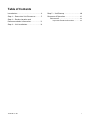
SStteepp 11 —— IInnssppeecctt SShhiippmmeenntt
1. Check for damage after the unit is unloaded. Report
promptly to the carrier any damage found to the
unit. Do not drop the unit.
IImmppoorrttaanntt:: To prevent damage to the sides and top of
the unit when hoisting, use “spreader
bars”.
2. Check the unit’s nameplate to determine if the unit
is correct for the intended application. The power
supply must be adequate for both the unit and all
accessories.
3. Check to be sure the refrigerant charge has been
retained during shipment. Remove the Compressor
access panel to access the 1/4" flare pressure taps.
4. If this unit is being installed on a curb, verify that
the correct curb is provided with the unit.
• 4WCC4024–036 use model BAYCURB050A,
4WCC4042–060 use model BAYCURB051A
5. If the unit is being hoisted, accessory kit
BAYLIFT002A is recommended. It includes a kit of
four (4) lifting lugs and instructions.
NNoottee:: If practical, install any internal accessories to the
unit at the shop.
NNoottee:: The packaged units have been evaluated in
accordance with the Code of Federal Regulations,
Chapter XX, Part 3280 or the equivalent.
“SUITABLE FOR MOBILE HOME USE.”

18-EB29D1-1F-EN
5
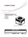
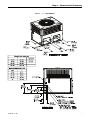
Step 2 — Determine Unit Clearances
Figure 1. 2 — 3 TON MODELS
Note: The view labeled Bottom Side
represents the base as viewed looking
up from underneath the unit.

6
18-EB29D1-1F-EN
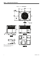
Figure 2. 2 — 3 TON MODELS
Model
Height MM/IN
APPROX. CORNER WEIGHT
KG /
LBS
SHIPPING
WIGHT
KG / LBS
TOTAL
UNIT
WEIGHT
KG / LBS
CENTER OF GRAVITY
MM/IN.
A
W1
W2
W3
W4
B
C
4TCC4024
898.53 [35 - 3/8]
58.3
[129]
36.8 [81]
26.1
[58]
41.0
[90]
196.1
(432)
162.4
(358)
479.8 [18.9]
527.8 [20.8]
4TCC4030
61.3
[135]
38.7 [85]
27.5
[61]
43.1
[95]
204.8
(451)
171.1
(377)
406.5 [16.0]
594.1 [23.4]
4TCC4036
61.7
[136]
38.9 [86]
27.7
[61]
43.7
[96]
205.7
(453)
172.0
(379)
414.3 [16.3]
697.6 [27.5]
4WCC4024
52.9
[117]
33.3 [73]
24.1
[53]
38.3
[84]
182.3
(402)
148.6
(328)
430 [16.9]
565.3 [22.3]
4WCC4030
55.3
[122]
50.3 [110]
16.6
[37]
39.2
[86]
195.0
(430)
161.3
(355)
413.5 [16.3]
581 [22.9]
4WCC4036
59.6
[131]
37.3 [82]
26.6
[59]
41.7
[92]
199.0
(439)
165.3
(364)
430 [17.0]
535 [21.1]
949.33 [37-3/8]
898.53 [35-3/8]
949.33 [37-3/8]
SStteepp 22 —— DDeetteerrmmiinnee UUnniitt CClleeaarraanncceess


18-EB29D1-1F-EN
9
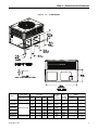
Figure 5. 3.5 — 5 TON MODELS
Model
Height MM/IN
APPROX. CORNER WEIGHT
KG /
LBS
SHIPPING
WIGHT
KG / LBS
TOTAL
UNIT
WEIGHT
KG / LBS
CENTER OF GRAVITY
MM/IN
A
W1
W2
W3
W4
B
C
4TCC4042
898.53 [35-3/8]
71.8
[158]
47.2 [104]
35.2
[78]
53.6
[118]
254.5
(561)
207.3
(457)
470.0 [18.5]
731.0 [28.8]
4TCC4048
72.0
[159]
45.0 [99]
33.8
[75]
54.4
[120]
252.6
(557)
205.4
(453)
433.0 [17.0]
743.3 [29.3]
4TCC4060
78.0
[172]
46.3 [102]
34.9
[77]
59.0
[130]
265.8
(586)
218.6
(482)
414.0 [16.3]
635.0 [25.0]
4WCC4042
64.4
[142]
47.6 [105]
39.5
[87]
49.9
[110]
248.6
(547.9)
201.4
(444)
449.6 [17.7]
641.8 [25.3]
4WCC4048
1050.93 [41
-
3/8]
68.9
[152]
40.8 [90]
30.8
[68]
52.2
[115]
240.0
(529)
192.8
(425)
414.0 [16.3]
635.0 [25.0]
4WCC4060
79.4
[175]
47.2 [104]
35.8
[79]
59.9
[132]
269.5
(594)
222.3
(490)
414.0 [16.3]
635.0 [25.0]
1000.13 [39-3/8]
SStteepp 22 —— DDeetteerrmmiinnee UUnniitt CClleeaarraanncceess


18-EB29D1-1F-EN
11
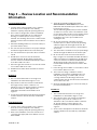
Step 3 — Review Location and Recommendation
Information
HHoorriizzoonnttaall AAiirrffllooww UUnniittss
1. Location of the unit must allow service clearance
around it to ensure adequate serviceability,
maximum capacity, and peak operating efficiency.
2. These units are designed for outdoor installation.
They may be installed directly on a slab, wood
flooring, or on Class A, B, or C roof covering
material. The discharge air from the condenser fans
must be unrestricted for a minimum of 3 feet above
the unit.
3. Check the handling facilities to ensure the safety of
personnel and the unit(s).
4. The unit must be mounted level for proper drainage
of water through the drain holes in the base pan.
5. The unit should not be exposed to direct roof water
runoff.
6. Flexible duct connectors must be of a flame
retardant material. All duct work outside of the
structure must be insulated and weatherproofed in
accordance with local codes.
7. Holes through exterior walls or roof must be sealed
in accordance with local codes.
8. All fabricated outdoor ducts should be as short as
possible.
CClleeaarraanncceess
1. The recommended clearances for single-unit
installations are illustrated in Figures 1 to 6.
2. Any reduction of the unit clearances indicated in
these figures may result in condenser coil
starvation or the recirculation of warm condenser
air. Actual clearances, which appear to be
inadequate should be reviewed with a local
engineer.
3. See the unit’s nameplate for the absolute minimum
clearance between the unit and any combustible
surfaces.
DDoowwnn AAiirrffllooww UUnniittss
1. Location of the unit must allow service clearance
around it to ensure adequate serviceability,
maximum capacity, and peak operating efficiency.
2. Refer to the Installation section for instruction on
converting the supply and return airflow covers to
down airflow.
3. The field assembled Roof Mounting Curb
(BAYCURB050A or BAYCURB051A) or a field
fabricated curb should be in place before the unit is
hoisted to the roof top.
The Roof Mounting Curb (frame) must be installed
on a flat, level section of the roof (maximum of 1/4"
per foot pitch) and provide a level mounting surface
for the unit. Also, be sure to provide sufficient
height above the roof to prevent water from
entering the unit.
4. Be sure the mounting curb spans structural
members (trusses) of the roof, thereby providing
sufficient support for the weight of the unit, the
curb, the duct(s), and any factory or field installed
accessories.
5. The unit must be mounted level for proper drainage
of water through the drain holes in the base pan.
6. Be sure the hole in the structure for the ducts is
large enough to accommodate the fabricated ducts
and the insulation surrounding them. Flexible duct
connectors must be of a flame retardant material.
All duct work outside of the structure must be
insulated and weatherproofed in accordance with
local codes.
7. Holes through exterior walls or roof must be sealed
in accordance with local codes.
8. These units are design certified for outdoor
installation. They may be installed directly on a
slab, wood flooring, or on Class A, B, or C roof
covering material. The discharge air from the
condenser fans must be unrestricted for a minimum
of 3 feet above the unit.
9. Check the handling facilities to ensure the safety of
personnel and the unit(s).
CClleeaarraanncceess
1. The recommended clearances for single-unit
installations are illustrated in Figures 1 to 6.
2. Any reduction of the unit clearances indicated in
these figures may result in condenser coil
starvation or the recirculation of warm condenser
air. Actual clearances, which appear to be
inadequate should be reviewed with a local
engineer.
3. See the unit’s nameplate for the absolute minimum
clearance between the unit and any combustible
surfaces.

12
18-EB29D1-1F-EN
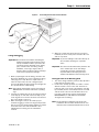
Step 4 — Unit Installation
NNoottee:: The factory ships this unit for horizontal
installation.
TToo IInnssttaallll tthhee uunniitt aatt ggrroouunndd lleevveell::
1. Place the unit on a pad the size of the unit or larger.
The unit must be mounted level for proper drainage
of water through the holes in the base pan. To
attach the unit securely to the slab, use extreme
mounting kit, BAYEXMK003A.
The pad must not come in contact with the
structure. Be sure the outdoor portion of the supply
and return air ducts are as short as possible.
2. Location of the unit must allow service clearance
around it. Clearance of the unit must be given
careful consideration. See Figures 1 to 6.
NNoottee:: Any reduction of the unit clearances indicated
in these illustrations may result in condenser
coil starvation or the recirculation of warm
condenser air. Actual clearances, which
appear to be inadequate should be reviewed
with a local engineer.
IImmppoorrttaanntt:: A minimum 0" clearance to combustible
material shall be maintained on air
outlet duct.
3. Attach the supply and return air ducts to the unit as
explained in the ductwork Installation section.
4. Flexible duct connectors must be of a flame
retardant material. Insulate any ductwork outside of
the structure with at least two (2) inches of
insulation and weatherproof. There must be a
weatherproof seal where the duct enters the
structure.
5. Do not expose the unit to direct roof water runoff.
6. Seal all holes through exterior walls in accordance
with local codes.
7. Continue with the following installation sections to
complete the installation: Ductwork, Filter and
Electrical Wiring.
RRooooffttoopp IInnssttaallllaattiioonn —— CCuurrbb MMoouunnttiinngg
CCoonnvveerrtt HHoorriizzoonnttaall AAiirrffllooww ttoo DDoowwnn AAiirrffllooww
The factory ships the unit for horizontal airflow.
Perform this procedure to convert it to down airflow:
1. Remove the three (3) sheet metal screws securing
the supply air cover and the four (4) sheet metal
screws securing the return air cover from the base
of the unit. Remove the covers from the base.
2. Place the covers over the horizontal supply and
return openings (painted side out). Align the screw
holes, and secure using the same screws removed
in step 1.
IInnssttaallll FFuullll PPeerriimmeetteerr RRooooff MMoouunnttiinngg CCuurrbb
1. Verify that the roof mounting curb is correct for the
unit. There are two curbs depending on the unit
cabinet sizes:
• 4WCC4024–036 use model BAYCURB050A,
4WCC4042–060 use model BAYCURB051A
2. Assemble and install the curb following the
instructions in the Installer's Guide included with
the appropriate curb.
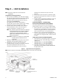
Figure 7. Typical Ground Level Application
NNoottee:: Use the extreme mounting kit, BAYEXMK003AA, to secure the unit to the slab.
SIDING
RETURN
AIR DUCT
SUPPLY
AIR DUCT
EXTERIOR
WALL
INSULATE
WEATHERPROOF
OR RAIN SHIELD
FLEXIBLE DUCT
CONNECTORS
OUTDOOR
AIR DISCHARGE
SUPPORT PAD
FOUNDATION
3/4” VIBRATION ISOLATORS, USE
7 ISOLATORS

18-EB29D1-1F-EN
13
Figure 8. Converting Horizontal to Down Airflow
LLiiffttiinngg aanndd RRiiggggiinngg
IImmppoorrttaanntt:: Do not lift the unit without test lifting for
balance and rigging. Do not lift the unit in
windy conditions or above personnel. Do
not lift the unit by attaching clevis, hooks,
pins, or bolts to the unit casing, casing
hardware, corner lugs, angles, tabs, or
flanges. Failure to observe these warnings
may result in equipment damage.
1. Before preparing the unit for lifting, check the unit
dimension drawings for center of gravity for lifting
safety (Figures 1 to 6). Because of placement of
internal components, the unit’s weight may be
unevenly distributed. Approximate unit weights are
also provided in the unit drawings
NNoottee:: Unit rigging and hoisting requires accessory kit
BAYLIFT002A. It includes a kit of four (4) lifting
lugs.
2. Insert the four lifting lugs in the openings provided
in the drip lip on each end of the unit. A tap or jerk
to the lug will overcome the interference that arises
due to the dimple on the lug.
3. When hoisting the unit, be sure that a proper
method of rigging is used. Use slings and spreader
bars for protection during lifting. Always test-lift the
unit to determine the exact unit balance and
stability before hoisting it to the installation
location.
4. When the curb and air ducts have been properly
installed, the unit is ready to be hoisted to the roof
and set in position.
IImmppoorrttaanntt:: To prevent damage to the sides and top of
the unit when hoisting use “spreader
bars”.
IImmppoorrttaanntt:: The unit must be lowered into position. The
P.V.C. rubber tape on the curb flange
permits the unit to be repositioned if
required without destroying the P.V.C.
rubber seals affixed to the mounting curb.
PPllaacciinngg tthhee UUnniitt oonn tthhee MMoouunnttiinngg CCuurrbb
1. The unit is designed with a perimeter drip lip that is
lower than the unit base pan.
2. Position the unit drip lip down over and in contact
with the outside corner of the curb.. Continue to
lower the unit on top of the curb, with the unit drip
lip astraddle, and in contact with, both the end and
side rail of the curb. The unit should now rest on
top of the curb. Use the extreme mounting kit,
BAYEXMK001A, to add additional hold down
strength to the mounting.
NNoottee:: The ductwork is installed as part of the curb
installation. Do not attach ductwork to the unit
and lower the unit with ductwork onto the curb.
SStteepp 44 —— UUnniitt IInnssttaallllaattiioonn

14
18-EB29D1-1F-EN
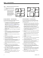
Table 1. Vibration Isolators/Snow Feet Locations
Note: These views represent the base as
viewed looking up from underneath
the unit.
Important: Unit requires vibration isolator
support in the general areas
shown. Locate 3/4" thick
vibration isolators on the
bottom of the basepan as
illustrated by black dots for
ground level pad applications.
Modify vibration isolator
location as necessary for frame
and rail applications.
Small Cabinet
****4024 - 4036
Medium Cabinet
****4042 - 4060
RRooooffttoopp IInnssttaallllaattiioonn —— FFrraammee MMoouunnttiinngg
For rooftop applications using field fabricated frame
and ducts use the following procedure:
1. Locate and secure the frame to the roof by bolting
or welding. Frame must provide adequate center
support via a cross member centrally located
channel rail. See Table 5, p. 16. Vibration isolators
should be installed as indicated in Table 1, p. 14,
adjust as necessary for your frame. The isolators
must be placed on base pan, not drip lip. Add
flashing as required. Flashing must conform to local
building codes.
2. Prepare the hole in the roof in advance of installing
the unit.
3. Secure the horizontal or down airflow ducts to the
roof. Refer to the previous Convert from Horizontal
Airflow to Down Airflow section if conversion is
needed.
4. All fabricated outdoor ducts should be as short as
possible.
5. Place the unit on the frame.
6. The unit must be mounted level for proper drainage
of water through the holes in the base pan.
7. Secure the unit to the frame.
8. Insulate any ductwork outside of the structure with
at least two (2) inches of insulation and then
weatherproof. There must be a weatherproof seal
where the duct enters the structure.
9. The unit should not be exposed to direct roof water
runoff.
10. Flexible duct connectors must be of a flame
retardant material. All duct work outside of the
structure must be insulated and weatherproofed in
accordance with local codes.
11. Access and service clearances for the unit must be
given careful consideration when locating the duct
entrance openings. Figures 1 to 6 provide unit
dimensions.
12. Continue with the following installation sections to
complete the installation: Ductwork, Filter, and
Electrical Wiring.
RRooooffttoopp IInnssttaallllaattiioonn —— FFrraammee MMoouunnttiinngg
For roof top applications using field fabricated ducts
and sleeper rails rather than a curb or frame, use the
following procedure:
1. Locate and secure the sleeper rails to the roof by
bolting (three (3) rails required). One on each end to
support the edges of the unit and one across the
center of the unit. The center rail must run inside
both drip lips. Vibration isolators should be
installed, adjust as necessary for your sleeper rails.
The isolators must be placed on base pan, not drip
lip. Add flashing as required. Flashing must
conform to local building codes.
2. Prepare the hole in the roof in advance of installing
the unit.
3. Secure the horizontal or down airflow ducts to the
roof. Refer to the previous Convert from Horizontal
Airflow to Down Airflow section if conversion is
needed.
4. All fabricated outdoor ducts should be as short as
possible.
5. Place the unit on the rails.
6. The unit must be mounted level for proper drainage
of water through the holes in the base pan.
7. Secure the unit to the rails.
8. Insulate any ductwork outside of the structure with
at least two (2) inches of insulation and then
weatherproof. There must be a weatherproof seal
where the duct enters the structure.
9. No exposure to direct roof water runoff.
10. Flexible duct connectors must be of a flame
retardant material. All duct work outside of the
structure must be insulated and weatherproofed in
accordance with local codes.
11. Access and service clearances for the unit must be
given careful consideration when locating the duct
entrance openings. Figures 1 to 6 provide unit
dimensions.
12. Continue with the following installation sections:
Ductwork, Filter and Electrical Wiring.
SStteepp 44 —— UUnniitt IInnssttaallllaattiioonn

18-EB29D1-1F-EN
15
Table 2. Lifting and Rigging
Base of unit
rest on top of
curb rails
Drip lip on
perimeter of
unit
Spreader Bars
Gasket Seal
Drip Lip
Dimple
BAYLIFT002A
Lifting Lugs
Table 3. Curb Dimensions
This drawing was prepared by the manufacturer in order to provide detail regarding job layout only. This drawing is not intended to be used as a
basis to construct, build or modify the item depicted in the drawing. The manufacturer is not responsible for the unauthorized use of this
drawing and expressly disclaims any liability for damages resulting from such unauthorized use.
SStteepp 44 —— UUnniitt IInnssttaallllaattiioonn

16
18-EB29D1-1F-EN
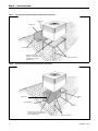
Table 4. Typical Rooftop Horizontal Airflow Application with Frame
Supply Air
Return Air
Roof Flashing
Channel Iron Center
Support (Center Support
required on all frame
applications).
Angle Iron Frame
Table 5. Typical Rooftop Down Airflow Application with Frame
Return Air
Roof Flashing
Channel Iron Center Support
(center support required on all
frame applications).
Angle Iron Frame
Roof
Flashing
Supply
Air
SStteepp 44 —— UUnniitt IInnssttaallllaattiioonn

18-EB29D1-1F-EN
17
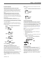
DDuuccttwwoorrkk IInnssttaallllaattiioonn
AAttttaacchhiinngg DDoowwnnffllooww DDuuccttwwoorrkk ttoo RRooooff CCuurrbb
Supply and return air flanges are provided on the roof
curb for easy duct installation. All ductwork must be
run and attached to the curb before the unit is set into
place.
AAttttaacchhiinngg DDoowwnnffllooww DDuuccttwwoorrkk ttoo RRooooff FFrraammee
Follow these guidelines for ductwork construction:
Connections to the unit should be made with three (3)
inch canvas connectors to minimize noise and vibration
transmission.
Elbows with turning vanes or splitters are
recommended to minimize air noise and resistance.
The first elbow in the ductwork leaving the unit should
be no closer than two (2) feet from the unit, to minimize
noise and resistance.
To prevent leaking, do not attach the ductwork to the
bottom of the unit base. Refer to the bottom example in
the figure below.
Figure 9. Attaching Down Airflow Ductwork
FIELD DUCT
UNIT DUCT
FLANGE
UNIT BASE
AIR PROOF
THIS SEAM
FIELD DUCT
UNIT DUCT
FLANGE
UNIT BASE
AIR PROOF
THIS SEAM
FIELD
DUCT
UNIT DUCT FLANGE
UNIT BASE
AIR PROOF
THIS SEAM
FIELD DUCT
UNIT DUCT
FLANGE
UNIT BASE
NOT RECOMMENDED
WATERPROOF SEAM
WITH BUTYL OR
SILICONE
AAttttaacchhiinngg HHoorriizzoonnttaall DDuuccttwwoorrkk ttoo UUnniitt
All conditioned air ductwork should be insulated to
minimize heating and cooling duct losses. Use a
minimum of two (2) inches of insulation with a vapor
barrier. The outside ductwork must be weatherproofed
between the unit and the building.
When attaching ductwork to a horizontal unit, provide a
flexible watertight connection to prevent noise
transmission from the unit to the ducts. The flexible
connection mmuusstt be indoors and made out of heavy
canvas.
NNoottee:: Do not draw the canvas taut between the solid
ducts.
Figure 10. Attaching Horizontal Airflow Ductwork
FIELD DUCT
UNIT EXTERIOR
WEATHERPROOF
THIS SEAM
FIELD DUCT
UNIT EXTERIOR
WEATHERPROOF
THIS SEAM
CCoonnddeennssaattee DDrraaiinn PPiippiinngg
A 3/4-inch female NPT condensate drain connection is
provided on the evaporator access panel end of the
unit. Provide a trap and fill it with water before starting
the unit to avoid air from being drawn through. Follow
local codes and standard piping practices when
running the drain line. Pitch the line downward away
from the unit. Avoid long horizontal runs. See Figure
11, p. 17.
NNoottee:: Do not use reducing fittings in the drain lines.
The condensate drain must be:
• Made of 3/4” pipe size
• Pitched 1/4” per foot to provide free drainage to
convenient drain system
• Trapped
• Must be connected to a closed drain system unless
the trap is properly vented
Figure 11. Typical Condensate Drain Piping
3
/
4
" PVC OR COPPER
TUBING AND FITTINGS
1-1/2" MIN.
1-1/2" MIN.
AAiirr FFiilltteerr IInnssttaallllaattiioonn
The packaged unit requires an air filter. The unit does
not come with a factory installed filter rack in it,
however, two filter frame accessories are offered that
will allow the installation of a filter within the unit,
BAYFLTR101 & BAYFLTR201. Otherwise a field
supplied filter rack must be installed by the installer in
the return duct work. Refer to table for field supplied
filter racks.
SStteepp 44 —— UUnniitt IInnssttaallllaattiioonn

18
18-EB29D1-1F-EN
Table 6. Filter Sizes (field supplied filter rack)
UNIT
NOMINAL
CFM
FILTER
(a)
SIZE
(Sq Ft)
FILTER
RESISTANCE
(“W.C.)
4~CC4024A 800 2.67 0.08
4~CC4030A 1000 3.33 0.08
4~CC4036A 1200 4.00 0.08
4~CC4042A 1400 4.67 0.08
4~CC4048A 1600 5.33 0.08
4~CC4060A 2000 6.67 0.08
(a)
fFilters must be installed in the return air system. The above square
footages are based on 300 F.P.M. face velocity. If permanent filters
are used, size per mfg. Recommendation with clear resistance of
0.05”WC.
IImmppoorrttaanntt:: Air filters and media wheels or plates shall
meet the test requirements in UL 900
EElleeccttrriiccaall WWiirriinngg
NNoottee:: This unit is factory wired for 230V. See wiring
diagram for 208V conversion.
EElleeccttrriiccaall CCoonnnneeccttiioonnss
Electrical wiring and grounding must be installed in
accordance with local codes or, in the absence of local
codes, with the National Electrical Code ANSI/NFPA 70,
Latest Revision.
EElleeccttrriiccaall PPoowweerr
It is important that proper electrical power be available
for the unit. Voltage variation should remain within the
limits stamped on the unit nameplate.
DDiissccoonnnneecctt SSwwiittcchh
Provide an approved weatherproof disconnect within
close proximity and wwiitthhiinn ssiigghhtt ooff tthhee uunniitt..If
disconnect must be mounted to the cabinet, the
location shown in Table 9, p. 18 should be the only one
considered.
OOvveerr CCuurrrreenntt PPrrootteeccttiioonn
The branch circuit feeding the unit must be protected
as shown on the unit's rating plate.
PPoowweerr WWiirriinngg
The power supply lines must be run in weather-tight
conduit to the disconnect and into the side of the unit
control box. Provide strain relief for all conduit with
suitable connectors.
Provide flexible conduit supports whenever vibration
transmission may cause a noise problem within the
building structure.
1. Remove the Control/Heat access panel. Pass the
power wires through the Power Entry hole in the
end of the unit. See Table 7, p. 18.
2. Connect the high voltage wires to the appropriate
contactor terminals. Single phase units use a two
(2) pole contactor and three phase units use three
(3) pole contactor. Connect the ground to the
ground lug on the chassis. See Table 9, p. 18.
Ensure all connections are tight.
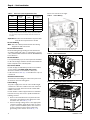
Table 7. Power Wiring
Run power supply lines through weather-tight
conduit and secure to unit with strain relief.
Table 8. Power Connections
Unit Ground
Lug
Contactor
Table 9. Mounted Disconnect Location
SStteepp 44 —— UUnniitt IInnssttaallllaattiioonn

18-EB29D1-1F-EN
19
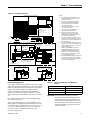
Table 10. Field Wiring Diagram
COMMON
FAN
COMPRSSOR
1ST STAGE ELECTRIC HEAT
2ND STAGE ELECTRIC HEAT
SWITCHOVERVALVE
DEFROST CONTROL 'T' SIGNAL
24 VOLTS
B
G
Y
W1
W2
O
T
R
UNIT LOWVOLTAGE AREA
TYPICAL THERMOSTAT
UNIT HEATER AREA
ELECTRIC
HEATER
CONTROL
BOX
POLARIZED
PLUG
UNIT CONTROL BOX
3 PH
POWER
UNIT
NOTE 1,8
3 PH
POWER
HEATER
1 PH
POWER
1 PH
POWER
UNIT CONTROL
BOX
UNIT HEATER AREA
FACTORY PROVIDED
FIELD CONNECTED
WIRES
(BL)
(YL)
(GR)
(PR)
(OR)
(OR)
B
G
Y
W1
W2
O
T
R
(BR)
(RD)
(GR)
(BL)
(WH)
(WH)
(YL)
(OR)
1 PH
POWER
3 PH
POWER
GROUND
WIRE
SINGLE POWR ENTRY
W1
W2
(WH)
(WH)
W 1
W 2
(WH)
(WH)
HEATER SECOND STAGE AMBIENT
TEMPERATURE LOCKOUT
NOTE 7,8
UNIT LOW
VOLTAGE
AREA
OUTDOOR
THERMOSTAT
ACCESSORY
BAYSTAT033A
NOTE 10
HEATER AMBIENT
TEMPERATURE LOCKOUT
NOTE 7,8
UNIT LOW
VOLTAGE
AREA
OUTDOOR
THERMOSTAT
ACCESSORY
BAYSTAT033A
NOTE 10
TYPICAL THERMOSTAT
TYPICAL THERMOSTAT
TYPICAL 2-STAGE
THERMOSTAT
UNIT LOW
VOLTAGE AREA
UNIT LOW
VOLTAGE AREA
TO COMPR.
CONTACTOR
ELECTRIC
HEATER
CONTROL
BOX
HEATER
FUSES
UNIT
FUSES
SPE
ACCESSORY
KIT
TO ECONOMIZER
FACTORY PROVIDED
FIELD INSTALLED WIRES
NOTE 9
(NOT APPLICABLE TOTHE
WCM---F MODELS)
FIG. 3 OUTDOOR THERMOSTAT ACCESSORY CONNECTIONS
FIG. 1
SINGLE POWER ENTRY ACCESSORY CONNECTIONS FIG. 2 ECONOMIZER ACCESSORY
CONNECTIONS
GROUND
WIRE
SEE SPEK INSTALLER'S GUIDE
FOR ALL OTHER EXAMPLES
PACKAGED HEAT PUM P UNIT
Notes:
1. Fused disconnect size, power wiring
and grounding of equipment must
comply with codes..
2. Be sure power supply agrees with
equipment and heater nameplate.
3. Low voltage wiring to be 18 AWG
minimum conductor.
4. See heater nameplate for current
rating of heater used.
5. See unit and heater diagram for
electrical connection details.
6. If electric heater accessory is not
installed, omit the electric heater,
associated power wires and the “W”
and “X2” thermostat wires.
7. Fig 3 demonstrates connection of the
outdoor thermostat accessory only. For
further unit connection details refer to
the other figures.
8. The W1 wire is first stage electric heat.
If the electric heater accessory has two
heating stages, the W2 wire is second
stage electric heat..
9. When the BAYECON101A/102A or
BAYECON200A/201A economizer is
installed, the BAYRLAY004A relay
accessory kit is required to interface
the economizer to the heat pump for
proper system operation.
10. The BAYSTAT033A outdoor thermostat
accessory kit contains a thermostat
and a relay. The relay is not required to
be used in this application.
CCoonnttrrooll WWiirriinngg ((CCllaassss IIII))
Low voltage control wiring should not be run in conduit
with power wiring unless Class 1 wire of proper voltage
rating is used. Route the thermostat cable or equivalent
single leads of No. 18 AWG colored wire from the
thermostat subbase terminals through the rubber
grommet on the unit. See Figures 1–6 for the control
entry (24V Entry) location. Make connections as shown
on
Do not short thermostat wires since this will damage
the control transformer.
Refer to the table below for recommended wire sizes
and lengths for installing the unit thermostat. The total
resistance of these low voltage wires must not exceed
one (1) ohm. Any resistance in excess of 1 ohm may
cause the control to malfunction because of the
excessive voltage drop.
Table 11. Thermostat Wire Size and Maximum
Length
Wire Size
Maximum Length (Ft)
18 75
16 125
14 200
IImmppoorrttaanntt:: Upon completion of wiring, check all
electrical connections, including factory
wiring within the unit, and make sure all
connections are tight. Replace and secure
all electrical box covers and access panels
before leaving the unit or turning on the
power to the unit.
SStteepp 44 —— UUnniitt IInnssttaallllaattiioonn

20
18-EB29D1-1F-EN
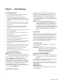
Step 5 — Unit Startup
PPrree--SSttaarrtt QQuuiicckk CChheecckklliisstt
☐ Is the unit properly located and level with the
proper clearances? See Figures 1–6.
☐ Is the duct work correctly sized, run, taped,
insulated, and weatherproofed with proper unit
arrangement as shown in the ductwork installation
section?
☐ Is the condensate line properly sized, run, trapped,
and pitched and shown in the Condensate Drain
Piping section?
☐ Is the filter of the correct size and quantity? Is it
clean and in place? See Air Filter Installation
section.
☐ Is the wiring properly sized and run according to the
unit wiring diagram?
☐ Are all the wiring connections, including those in
the unit tight?
☐ Has the unit been properly grounded and fused
with the recommended fuse size?
☐ Is the thermostat well located, level, and correctly
wired? See Electrical Wiring section
☐ Have the air conditioning systems been checked at
the service ports for charge and leak tested if
necessary?
☐ Do the condenser fan and indoor blower turn free
without rubbing and are they tight on the shafts?
☐ Has all work been done in accordance with
applicable local and national codes?
☐ Are all covers and access panels in place to prevent
air loss and safety hazards?
SSttaarrttiinngg tthhee UUnniitt iinn CCoooolliinngg MMooddee
NNoottee:: See the section on Sequence of Operation for a
description of the cooling operating sequence.
To start the unit in the cooling mode, set the comfort
control to CCOOOOLL and to a setting below room
temperature. The condenser fan motor, compressor
and evaporator fan motor will operate automatically.
Continuous fan mode during Cooling operation may
not be appropriate in humid climates. If the indoor air
exceeds 60% relative humidity or simply feels
uncomfortably humid, it is recommended that the fan
only be used in the AAUUTTOO mode.
OOppeerraattiinngg PPrreessssuurree CChheecckkss
After the unit has operated in the cooling mode for a
short period of time, install pressure gauges on the
gauge ports of the discharge and suction line valves
(behind the Compressor access panel). Check the
suction and discharge pressures and compare them to
the normal operating pressures provided in the unit’s
SERVICE FACTS.
NNoottee:: Do not use the PRESSURE CURVES from the
unit's SERVICE FACTS to determine the unit
refrigerant charge. The correct charge is shown
on the unit nameplate. To charge the system
accurately, weigh in the charge according to the
unit nameplate and check subcooling against the
Subcooling Charging Table in the SERVICE
FACTS.
VVoollttaaggee CChheecckk
With the compressor operating, check the line voltage
at the unit (contactor is located behind the Control
access panel). The voltage should be within the range
shown on the unit nameplate. If low voltage is
encountered, check the size and length of the supply
line from the main disconnect to the unit. The line may
be undersized for the length of the run.
CCoooolliinngg SShhuutt DDoowwnn
Set the comfort control to OOFFFF or to a setting above
room temperature.
IImmppoorrttaanntt:: De-energize the main power disconnect
ONLY when servicing the unit. Power may
be required to keep the heat pump
compressor warm and to boil off
refrigerant in the compressor.
SSttaarrttiinngg tthhee UUnniitt iinn HHeeaattiinngg MMooddee
NNoottee:: See the section on Sequence of Operation for a
description of the heat pump heating operating
sequence.
Check that all grills and registers are open and all unit
access panels are closed before start-up.
Set the comfort control above room temperature until
achieving a first stage call for heat and set the fan to
AAUUTTOO or OONN.
HHeeaattiinngg SShhuutt DDoowwnn
Set the comfort control to OOFFFF or at a setting below
room temperature.
Page is loading ...
Page is loading ...
Page is loading ...
Page is loading ...
-
 1
1
-
 2
2
-
 3
3
-
 4
4
-
 5
5
-
 6
6
-
 7
7
-
 8
8
-
 9
9
-
 10
10
-
 11
11
-
 12
12
-
 13
13
-
 14
14
-
 15
15
-
 16
16
-
 17
17
-
 18
18
-
 19
19
-
 20
20
-
 21
21
-
 22
22
-
 23
23
-
 24
24


Ingersoll-Rand 4WCA4024A1000A Installation guide
- Category
- Split-system air conditioners
- Type
- Installation guide
Ask a question and I''ll find the answer in the document
Finding information in a document is now easier with AI
Related papers
Other documents
-
Trane 4WHC3048 Installer's Manual
-
American Standard HVAC 4WCZ6048A3000B Installation guide
-
Broan Q4SE Installation guide
-
Daikin DCC Series Installation Instructions Manual
-
Carrier 50VL---A User manual
-
-
-
La Crosse 705-109 Installation guide
-
-
GOODMAN CPH048 User manual