CAUTION
SPIDER ALERT!
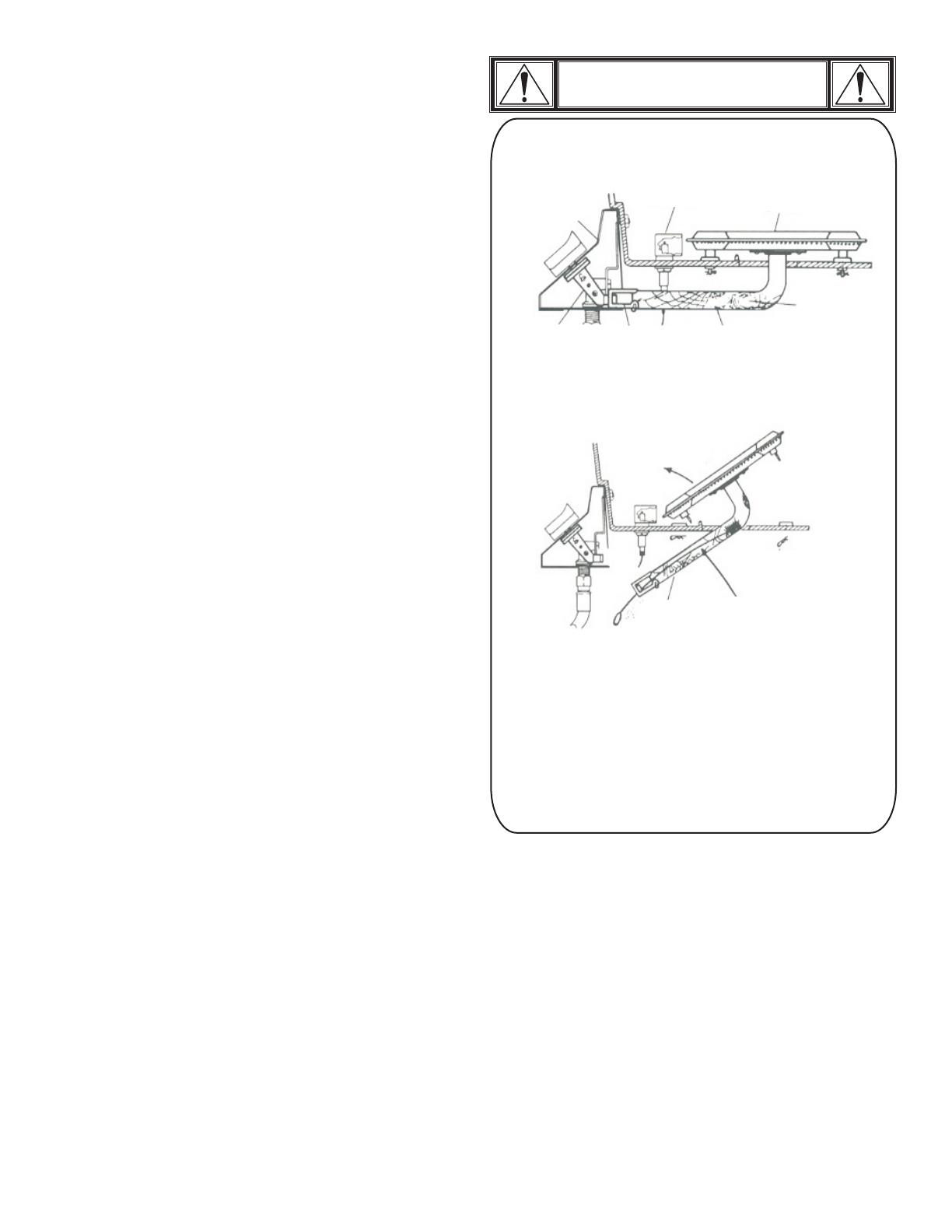
GAS COLLECTOR
BOX & IGNITOR
VALVE
CONTROL PANEL
BURNER
VENTURI
LIFT OUT
BURNER ASSEMBLY
AIR
SHUTTER
SPIDER WEBS
INSIDE VENTURI
SPIDER WEBS
INSIDE VENTURI
CLEAN OUT
VENTURI
REMOVE
BURNER
CLIPS
If you notice that your grill is getting hard to light or that the
flame isn’t as strong as it should be, take the time to check and
clean the venturi’s.
In some areas of the country, spiders or small insects have been
known to create “flashback” problems. The spiders spin webs, build
nests and lay eggs in the grill’s venturi tube(s) obstructing the flow of
gas to the burner. The backed-up gas can ignite in the venturi behind
the control panel. This is known as a flashback and it can damage
your grill and even cause injury.
To prevent flashbacks and ensure good performance the burner and
venturi assembly should be removed from the grill and cleaned
before use whenever the grill has been idle for an extended period.
Turning Grill Off
•Turn all knobs to OFF position. Turn LP tank off by turning
OPD hand wheel clockwise to a full stop.
Ignitor Check
•Turn gas off at LP tank. Press and hold ignitor button. "Click"
should be heard and spark seen each time between collector
box or burner and electrodes. See "Troubleshooting" if no click
or spark.
Valve Check
•Important: Make sure gas is off at LP tank before checking
valves. Knobs lock in OFF position. To check valves, first
push in knobs and release, knobs should spring back. If knobs
do not spring back, replace valve assembly before using grill.
Turn knobs to LO position then turn back to OFF position.
Valves should turn smoothly.
General Grill Cleaning
•Keep the outside of your grill looking new by cleaning it once a
month with warm soap and water or a non-abrasive cleaner. If
you don’t have a grill cover, wipe off dust and grime before
starting your grill.
• Coating the cooking grids with spray-on cooking oil will keep the
food from sticking and make clean up easier. After cooking,
scrape the grates with a long handled, brass wire bristle brush.
•Check inside the grill bottom for grease build up and clean
often, especially after cooking fatty meat.
•Do not mistake brown or black accumulation of grease and
smoke for paint. Apply a strong solution of detergent and water
or use a grill cleaner with scrub brush on insides of grill lid and
bottom. Rinse and allow to completely air dry. Do not apply a
caustic grill/oven cleaner to painted surfaces.
•Plated wire grates: Wash grates with concentrated grill
cleaner or use soap and water solution. Dry thoroughly and
store indoors between cookouts.
• Plastic parts: Wash with warm soapy water and wipe dry.
s Do not use citrisol, abrasive cleaners, degreasers or a
concentrated grill cleaner on plastic parts. Damage to and
failure of parts can result.
•Porcelain grates: Because of glass-like composition, most
residue can be wiped away with baking soda/water solution or
specially formulated cleaner. Use non-abrasive scouring
powder for stubborn stains.
•Painted surfaces: Wash with mild detergent or nonabrasive
cleaner and warm soapy water. Wipe dry with a soft
nonabrasive cloth.
•Stainless steel surfaces: To maintain your grill’s high quality
appearance, wash with mild detergent and warm soapy water
and wipe dry with a soft cloth after each use. Baked-on grease
deposits may require the use of an abrasive plastic cleaning
pad. Use only in direction of brushed finish to avoid damage.
Do not use abrasive pad on areas with graphics.
• Cooking surfaces: If a bristle brush is used to clean any of
the grill cooking surfaces, ensure no loose bristles remain on
cooking surfaces prior to grilling. It is not recommended to
clean cooking surfaces while grill is hot.
Storing Your Grill
• Clean cooking grates.
• Store in dry location.
• When LP tank is connected to grill, store outdoors in well-
ventilated space and out of reach of children.
• Cover grill if stored outdoors.
• Store grill indoors ONLY if LP tank is turned off and
disconnected, removed from grill and stored outdoors.
• When removing grill from storage follow "Cleaning Burner
Assembly" instructions before starting grill.
464722309 • 464722509 • 9


