- 6 -GH-PCU31-VH
English
Figure 1
Figure 2
Figure 3
Figure 4
Figure 1
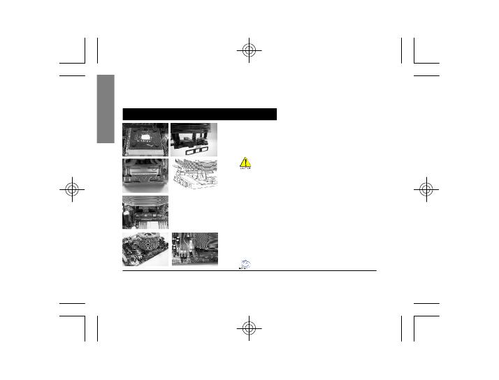
Please add an adequate layer of heat sink paste on the
surface of the CPU. Th e picture on the right shows the
three insert spaces on the cooler bracket where the CPU
clips attach.
Figure 2
Place the cool er atop the CPU an d insert the indication
arrow side of the coo ler in the space between the central
jut of the CPU socket and the ed ge of the CPU.
Figure 3
Align the three spaces on the cooler with the three clips
on the base of the CPU and then push firm ly downwards
to lock the cooler se curely i n place. A flat-head
screwdriver can also be used to secure the clips in place.
Figure 4
Connect the yellow 3-pin connector wir e of the coole r to
the CPU fan connector located on the motherboard.
Clip Installation is now com plete.
Attenti on!! The indic ation arr ow on the cooler must
align with the c entral CPU c lip.
Note: Pl ease refer to page 8 & 9 f or p ower installat ion
and installa tion of the fa n speed controller.
Installation Instructions for AMD Athlon XP Clip