7 Compatibility with ABUS products
8
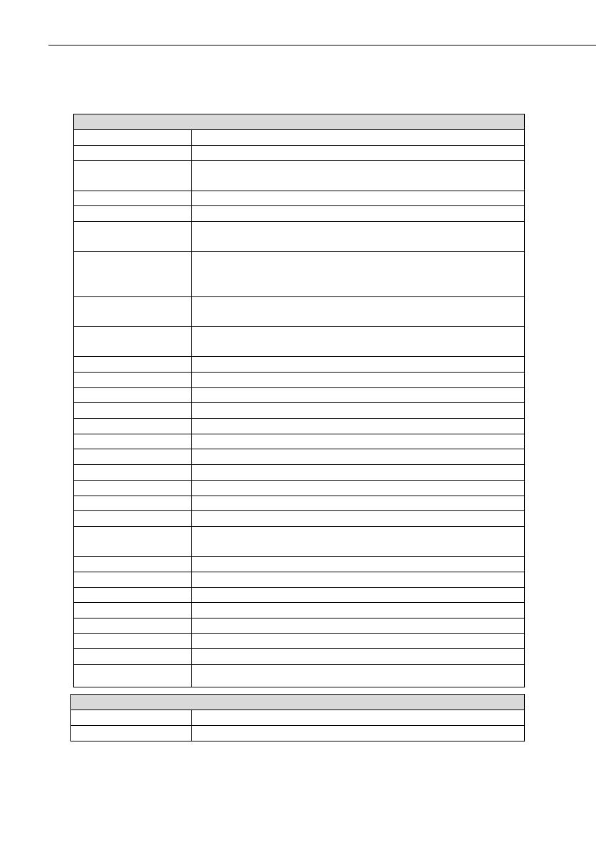
7. Compatibility with ABUS products
Compatible
CASA10010 IP alarm module
FU59xx Secvest Key 2WAY wireless cylinder
FU8100 Secvest 2WAY wireless remote control
(integrated panic function not usable)
FU8130 Secvest 2WAY wireless additional lock (7010E)
FU8140 Secvest 2WAY wireless additional lock (7025E)
FU8150 Secvest wireless remote control
(integrated panic function not usable)
FU8200 Secvest 2WAY wireless info module
(No display of: status ready / internally active / entry-
and exit delay time)
FU8210 / FU8211 Secvest 2WAY wireless universal module
(only repeater function)
FU8220 / FU8222 Secvest 2WAY wireless outdoor siren
(Beep acknowledgement as of FU8222)
FU8230 Secvest 2WAY wireless indoor siren
FU8240 Secvest wireless socket
FU8300 Secvest 2WAY wireless panic alarm
FU8305 Secvest 2WAY wireless panic transmitter
FU8310 Secvest 2WAY wireless fire alarm
FU8320W/B Secvest 2WAY wireless magnetic contact
FU8321W/B Secvest 2WAY wireless magnetic contact
FU8325W/B/S Secvest 2WAY mini wireless magnetic contact
FU8330 Secvest 2WAY wireless flood detector
FU8340 / FU8341 Secvest 2WAY wireless smoke detector
FU8350 Secvest 2WAY wireless motion detector
FU8360 Secvest 2WAY animal-immune wireless motion
detector
FU8370 Secvest 2WAY wireless glass breakage detector
FU8380 Secvest 2WAY wireless vibration detector
FU8390 Secvest 2WAY wireless emergency transmitter
FU841xW/B FTS 96 E wireless window lock
FU842x Secvest 2WAY wireless window bar lock (FOS550E)
FU8430W/B/S Secvest 2WAY wireless window handle (FG350E)
FU8435W/B/S Secvest 2WAY wireless window handle plus
TVIP41550 PIR network camera
Not compatible
FU8110 Secvest 2WAY wireless control unit
FU8165 Secvest 2WAY wireless key switch


