Page is loading ...

I
Save This Manual
For Future Reference
gJ _A/ S
owners
monuol
MODEL NO.
113.198410
10" DELUXEELECTRONIC
RADIAL SAW WITH
44" CABINET AND
2 DOORS
OR
t13.198610
10" DELUXEELECTRONIC
RADIAL SAWWITH
44" CABINET AND
6 DRAWERS
Serial
Number
Model and serial numlc_rs
may b_ found at the rear of
the bas_.
You should record both
model and serial number in
a safe place for future us_.
CAUTION:
READALL
INSTRUCTIONS
CAREFULLY
"x
MODEL 113,198610
MODEL 113.198410
CRRFTSMRN
IO-INCH DELUXEELECTRONIC
RADIAL SAW
• assembly
• operating
• repair parts
Sold by SEARS,ROEBUCKAND CO., Chicago, IL.60684 U.SJK.
Part No. SP5013 Printed in U.S.A

FULL ONE YEAR WARRANTY ON CRAFTSMAN RADIAL SAW
If within one year from the date of purchase, this Craftsman Radial Saw fails due to a defect in material or
workmanship, Sears will repair it, tree of charge.
WARRANTY SERVICE IS AVAILABLE BY SIMPLY CONTACTING THE NEAREST SEARS SERVICE
CENTER/DEPARTMENT THROUGHOUT THE UNITED STATES.
This warranty applies only while this produc! is used in the United States.
This warranty gives you specific legal rights and you may also have other rights which vary from state to state.
SEARS, ROEBUCK AND CO., DEPT. 698/731A Sears Tower, Chicago, IL 60684
GENERAL SAFETY INSTRUCTIONS FOR POWER TOOLS
1. KNOW YOUR POWER TOOL
Read and understand the owner's manual and
labels affixed to the tool. Learn its application
and limitations as well as the specific potential
hazards peculiar to this tool.
2. GROUND ALL TOOLS
This tool is equipped with an approved
3-conductor cord and a 3-prong grounding type
plug to fit the proper grounding type receptacle.
The green conductor in the cord is the grounding
wire. Never connect the green wire to a live
terminal.
3. KEEP GUARDS IN PLACE,
in working order, and in proper adjustment and
alignment.
4. REMOVE ADJUSTING KEYS AND WRENCHES
Form habit of checking to see that keys and
adjusting wrenches are removed from tool before
turning it on.
5. KEEP WORK AREA CLEAN
Cluttered areas and benches invite accidents.
Floor must not be slippery due to wax or sawdust.
6. AVOID DANGEROUS ENVIRONMENT
Don't use power tools in damp or wet locations or
expose them to rain. Keep work area well lighted.
Provide adequate surrounding work space.
7. KEEP CHILDREN AWAY
All visitors should be kept a safe distance from
work area.
8. MAKE WORKSHOP CHILD-PROOF
-- with padlocks, master switches, or by removing
starter keys.
9. DON'T FORCE TOOL
It will do the job better and safer at the rate for
which it was designed.
10. USE RIGHT TOOL
Don't force tool or attachment to do a job it was
not designed for.
11. WEAR PROPER APPAREL
Do not wear loose clothing, gloves, neckties or
jewelry (rings, wrist watches) to get caught in
moving parts. Nonslip footwear is recommended.
Wear protective hair covering to contain long
hair. Roll long sleeves above the elbow.
12. USE SAFETY GOGGLES (Head Protection)
Wear Safety goggles (must comply with ANSI
Z87.1) at all times. Everyday eyeglasses only
have impact resistant lenses, they are NOT
safety glasses. Also, use face or dust mask if
cutting operation is dusty, and ear protectors
(plugs or muffs) during extended periods of
operation.
13. SECURE WORK
Use clamps or a vise to hold work when practical.
It's safer than using your hand, frees both hands
to operate tool.
14. DON'T OVERREACH
Keep proper footing and balance at all times.
15. MAINTAIN TOOLS WITH CARE
Keep tools sharp and clean for best and safest
performances. Follow instructions for lubricating
and changing accessories.
16. DISCONNECT TOOLS
before servicing; when changing accessories
such as blades, bits, cutters, etc.
17. AVOID ACCIDENTAL STARTING
Make sure switch is in "OFF" position before
plugging in.
18. USE RECOMMENDED ACCESSORIES
Consult the owner's manual for recommended
accessories. Follow the instructions that accom-
pany the accessories. The use of improper acces-
sories may cause hazards.
19. NEVER STAND ON TOOL
Serious injury could occur if the tool istipped or
if the cutting tool is accidentally contacted. Do
not store materials above or near the tool such
that it is necessary to stand on the tool to reach
them.
20. CHECK DAMAGED PARTS
Before further use of the tool, a guard or other
part that isdamaged should be carefully checked
to ensure that itwill operate properly and perform
its intended function. Check for alignment of
moving parts, binding of moving parts, breakage
of parts, mounting, and any other conditions that
may effect its operation. A guard or other part
that id damaged should be properly repaired or
replaced.
21. DIRECTION OF FEED
Feed work into a blade or cutter against the
direction of rotation of the blade or cutter only.
22. NEVER LEAVE TOOL RUNNING UNATTENDED
Turn power off. Don't leave tool until it comes to
a complete stop.

additional
BEFORE USING THE SAW:
instructions for radial
arm saws
.e..d
3 =
€_
e--
WARNING: TO AVOID MISTAKES THAT COULD
RESULT IN SERIOUS, PERMANENT INJURY, DO
NOT CONNECT POWER CORD UNTIL THE FOL-
LOWING STEPS HAVE BEEN SATISFACTORILY
COMPLETED:
1. Assembly and alignment. (See pages 12-31)
2. Examination and operating familiarity with ON-
OFF switch, elevation hand wheel, swivel lock,
bevel lock and rip lock, guard clamp screw,
spreader and anti-kickback device and miter
lock. (See pages 37, 38 & 39.)
3. Review and understanding of all safety instruc-
tions and operating procedures throughout the
manual.
FOB YOUR OWN SAFETY:
1 Read an€ uncle(stand owner's _anua_
before 3perating machine
2 Wear s_,ely goggles compqying wilh
ANSI Z87 1
3 Keep hands Ou{ o1 path o¢ saw blade
4. Know he* to avoid "KICKBACKS.
5 USe "PUSH STfC K • for qarrow work
6 Never reach around Ihe saw blade
? Never perlorm any opef|l_on
'FREEHANO '
8 Returp carriaQe I_ the full rear posi_on
8fief e_h cros_ cul type o_ration
s shulof,po*ermad ai_ow_aw b_.d_Io
stop befo(e Ddiusllng of se_mcing
Read the following danger labels which appear on
the front of the radial arm saw base assembly, motor
and saw guard: _ WHENRIPPING
-- - TO AVOID m.'NAW=Y WORKm_OE
_ _ DA_R AT C,tn_
Know this tool:
1, Read and Under,land all warnlng_ an(3 instructlon_ o_
Saw, in Owners Manual and wilh recommended accea-
ttodes.
2 Properly guard the cuf_ng 3 Provtde proper workpl_e
tool. aupporl
4 Positlo_ the cutting _ool
.__ b_hind the lance by mov
Ing Ihe _rm to the tef'_ and
clamping the yoke SO this
label fa_n the lance; or
construct an au xill_ry
fence per Owner's Man-
ual
5 With power off Ihe aw+tch
-- key removed, 1urn cutting
1_ by hand qo make sure
It do_a no_ strike guard,
o3_f _ fl fence or any other saw
parts [[0,_,=_
WHEN INSTALLING OR MOVING THE
SAW
1. To avoid injury from unexpected carriage travel,
lock the rip lock handle before moving the saw.
2. To avoid injury from unexpected saw movement:
(a) Bolt the saw to the floor if it tends to slip,
walk, or slide during normal operation.
(b) When table extensions over 24" wide are
added to either side of the saw, make sure
you either bolt the saw to the floor or support
the outer end of the extension from the floor
as appropriate.
3. To avoid injury from unexpected carriage travel
adjust leveling feet so the arm tilts slightly
downward to the rear so that the carriage will not
roll forward due to gravity. Forward drift of the
carriage on an improperly leveled saw could
cause the blade to lunge forward due to un-
expected contact with the workpiece, fence,
table or part of your body.
BEFORE EACH USE
Plan your work.
-- To avoid injury from accidental starting, always
remove the plug from the outlet, turn the switch
off and remove the switch key before removing
the guard, changing the cutting tool, changing
the setup or making adjustments.
To avoid injury from blade contact, slips, shocks,
thrown pieces, etc., check the saw to make sure
that no parts are missing or broken, bent, or have
failed in any way, or any electrical component
fails to perform properly. Shut off power switch,
pull the plug from the outlet and replace damaged,
missing and/or failed parts before resuming
operation.
To avoid injury from electrical shock, make sure
your fingers do not contact the terminals when
installing or removing the plug to or from a live
outlet.
Check the fence for proper workpiece support. To
avoid fence breakage which could result in thrown
workpieces and blade contact, do not use fences
made of particle board or other composite
materials - use 3/4" thick lumber long enough to
extend in one piece from end to end of the saw
table, and tall enough to be at least even with the
top of the workpiece. Replace any fence where
existing slots in the fence have weakened the
fence or can snag the workpiece during ripping
operations. Always check table locks to make
sure any new fence is held securely (see page 27).
Choose your cutting tool carefully. Many saw
accidents are caused by use of the wrong type
blade, dull, badly set, improperly sharpened cut-
ting tools, gum or resin adhering to the cutting
tools, and by blade misalignment with the saw
fence. Such conditions can cause the material to
stick, jam (stall the saw), throw or "kickback" the
workpiece at the operator.
To avoid cutting tool failure and thrown shrapnel
(broken pieces of blade), use only blades or other
cutting tools marked for operating speeds 3450
rpm or higher. Never use a cutting tool larger in
diameter than the diameter for which the saw was
designed.
To avoid jamming of the blade, thrown work-
pieces, and damage to the blade collars, never
use a broken, warped, or unbalanced blade. Do
not overtighten arbor nut. Use arbor wrenches to
"snug" it securely.
To avoid injury from accidental blade contact by
the workpiece or the operator do not perform
layout, assembly, or setup work on the table

while the cutting tool is rotating. The rotating
tool could cut and throw anything hitting the
blade causing the saw to unexpectedly come
forward.
-- Use the right guard. To avoid losing control of the
workpiece, hitting the cutting tool, or being struck
by thrown pieces, never do any cutting unless the
proper guard (with all its parts in place) is installed
and adjusted properly.
-- To avoid injury from thrown pieces, slips, blade
contact, or jamming of the workpiece, make sure
no play exists between the column and column
support or in the carriage and that the arm, yoke,
bevel locks/clamps are tight.
--To avoid injury from thrown objects, slips or
jamming of the blade due to pinching of the blade
by shifting boards:
(a) Do not leavea long board unsupported so the
spring of the board causes it to twist or rise
from the table.
(b) Check to be sure that pieces will not fall off
the table once they have been cut.
(c) Provide support for the workpiece, based on
its size and the type of operation to be
performed. (See basic saw operation page
4O.)
(d) Never use another person as a substitute fora
table extension, or as an additional support
for a workpiece to assist in feeding, support-
ing, or pulling the workpiece.
(e) Never cut workpieces placed side to side or
stacked on top of each other. The pieces can
slide on each other.
WEAR YOUR
-- The operation of any power tool can result in
foreign objects being thrown into the eyes, which
can result in permanent eye damage. Always wear
safety goggles complying with ANSI Z87.1 (shown
on package). Safety goggles are available at
Sears retail catalog stores. Use of goggles or
glasses not in compliance with ANSI Z87.1 could
result in severe injury from breakage of the eye
protection.
-- To avoid injury from uncontrollable reaction or
thrown objects, never turn the saw "ON" before
clearing the table or work surface of all objects
(tools, scraps of wood, etc.) except the properly
supported workpiece and related feed or support
devices for the operation planned.
WHENEVER THE SAW IS RUNNING
-- Always keep alert. Do not allow familiarity (gained
from frequent use of your saw) to cause a careless
mistake. Always remember that a careless fraction
4
of a second is sufficient to inflict severe, permanent
injury.
If your saw makes an unfamiliar noise or if it
vibrates excessively, stop the operation immedi-
ately. Do not restart until the source has been
located and the problem corrected.
Do not cycle the motor switch "ON" and "OFF"
rapidly, as this might cause the sawblade to
loosen. In the event this should ever occur, turn
the switch off, allow the sawblade to come to a
complete stop, and remove the switch key. To
avoid damage to the blade and flange, retighten
the arbor nut normally, not excessively.
-- Never perform any operation freehand. Injury can
occur from blade contact or thrown pieces when
the workpiece is torn from the hands. "Freehand"
means feeding the sawblade into a workpiece or
feeding the workpiece into the sawblade or other
cutting tool without using the fence or some other
proper device to prevent the workpiece from
twisting and binding on the cutting tool during the
cutting operation.
-- To avoid accidental blade contact, avoid awkward
hand positions where a sudden slip causes a hand
to move toward the sawblade or other cutting
tool. Do not place fingers or hand on the work-
piece or table that is in the path of the sawblade.
-- To avoid being pulled into the back of the blade
before you can let go or react, never reach in back
of, or around the cutting tool, with either hand to
hold down the workpiece or for any reason.
-- To avoid injury from unexpected starting, never
attempt to free a stalled sawblade without first
turning the saw "OFF" and removing the switch
key. If the sawblade is stalled or jammed, shut the
saw "OFF", remove the switch key, remove the
workpiece, check for looseness in clamps, arm
and carriage, check the sawblade squareness to
the table surface and to the fence, and check for
heel (see page 29). Adjust as indicated.
-- To avoid injury from falling parts or from falling
into the saw, never climb on or near the saw when
its power is "ON". Never leave the saw area when
power is "ON", or before the cutting tool has
come to a complete stop.
-- To avoid unauthorized saw use, remove the switch
key and put the key away before leaving the saw
area.
BEFORE STARTING A RIPPING TYPE CUT
To avoid injury from being struck by a thrown
workpiece, position the saw so neither you, a
helper, or a casual observer is forced to stand in
line with the sawblade or workpiece.
Whenever possible, use the "in-rip" position. (See
page 44.) This provides maximum clearance for
feeding by hand, push stick, or push block as
appropriate.
-- To avoid thrown workpieces or being pulled into
the saw before you can react, push the workpiece

fromthenoseside(oppositethesawdustexhaust
chute)of theguard.Notethe warningon the
guard.
-- Toavoidinjuryfromthrownpieces,slips,orjams,
theworkpiecemustbehelddownonthetableand
againstthefence.Planyourhandplacementsto
safelyfeedtheworkpieceintothe cuttingtool.
Featherboardscanalsohelpkeeptheworkagainst
thefence.AfeatherboardismadeofsolidI_Jmher
persketch. --_ - -
jj '2._,'' _ i_---_KE-RF ABOUT " - _ "_
-- To avoid accidental blade contact, never position
the guard or anti-kickback assembly with the
power "ON" or the blade spinning.
-- When properly adjusted to just clear the work-
piece, the guard nose will help keep the workpiece
down on the table. To prevent injury from the
workpiece rising from the table, thrown chips
from the workpiece or blade, or hand slippage
towards the front of the blade, position the nose
guard to just clear the workpiece. (See page 39)
-- To maximize protection from the rear of the blade
and avoid injury from kickbacks, adjust the anti-
kickback and spreader devices as instructed.
(See page 31 & 39.)
-- To avoid injury from kickback, make sure by trial
before starting the cut that the anti-kickback
pawls will stop the kickback once it has started.
Make sure points of pawls are sharp. (See page
39.) Warning: Use extra care for non-thru cuts
because the anti-kickback pawls cannot always
grab the irregular surface created by the operation.
INSPECT YOUR WORKPIECE
-- To keep thesawblade from rising up on top of the
workpiece and throwing it back at the operator,
when sawing 1/4" or thinner materials, follow all
normal ripping procedures except set sawblade
into the table top at least 1/8".
-- To avoid kickback, use extra care when ripping
wood that has a twisted grain or is twisted or
bowed - it may rock on the table and/or pinch the
sawblade. If the workpiece cannot be made stable
against the fence and table top, do not cut it with a
radial arm saw.
-- To avoid blade contact and/or kickback, use a
push stick when ripping short (10 to 12 inches
long) or narrow (2 to 6-1/2 inches wide) work-
pieces. Use a push block as illustrated on page 43
for pieces 3/8 to 2 inches wide or, wherever
possible, place the wider section of the board
between the fence and the blade.
--To avoid kickbacks never feed a workpiece
through the saw with another piece (butting _"._--
second piece against trailing end of piece being "_
cut) even if of the same thickness, oo .,_
-- To keep control of your workpiece, never rip work -_=
shorter than the blade diameter.
-- For rip or rip-type cuts, the trailing end of the
workpiece to which a push stick or push board is
applied must be square (perpendicular to the
fence and table top) so that feed pressure applied
to the workpiece by the push stick or push block
will not cause the workpiece to come away from
the fence or rise from the table and possibly cause
a kickback.
--Plastic and composition (like particle board)
materials may be cut on your saw. However, since
these are often quite hard and slippery, the anti-
kickback pawls may not stop a kickback. To get
best performance, rip with the finished side down
(next to the table) and the roughest side up, and
be especially attentive to follow proper set up and
cutting procedures.
WHILE DOING A RIP TYPE OPERATION
-- Never reach around the blade to the outfeed side
to touch the portion of workpiece beyond the
blade until the whole workpiece has been pushed
beyond and clear of the blade. Your touch could
cause a kickback which could strike someone or
pull your hand into the rear (outfeed side) of the
blade before you can let go or react.
-- Position your body at the nose (in-feed) side of
the guard. Start and complete the cut from that
same side. This will require added table support
for tong or wide workpieces that extend beyond
the length or width of the saw table to prevent
workpiece from being thrown as it falls from the
table.
-- Never apply the feed force to the section of the
workpiece that will become the cutoff (free)
piece. Feed force when ripping must always be
applied between the sawblade and the fence so
that the slot cut by the blade (kerf) will not be
pinched shut on the blade causing a kickback.
Never touch the piece that has been cut off until
the blade has come to a complete stop.
--Keep pushing the section of the workplece
between the blade and the fence until the piece
has been pushed completely past the blade, so
the blade will not grab the piece and throw it back
at the operator.
BEFORE DOING A CROSSCUT TYPE CUT
--To avoid blade contact, do not perform any
operation that requires the cutting tool to extend
beyond the edges of the table used forsupporting
the workpiece.
--To maximize protection from accidental blade
contact and reduce risk of jamming objects into
the guard, place guard in a horizontal position
and adjust anti-kickback pawls to just clear the
top of the fence or the workpiece, whichever is
higher. The anti-kickback pawl assembly will

provide additional guarding from contact with the
front of the blade.
--To prevent the cutting tool from grabbing the
table or workpiece and being propelled toward
you, never lower a revolving cutting tool into the
table or a workpiece without first locking the rip
lock handle and clamping the workpiece in place.
Release the handle only after having firmly
grasped the carriage handle.
-- To avoid blade contact orinjuryfrom athrown cut
off piece, never use a length stop on the cut off
end or edge of theworkpiece. Never hang onto or
touch the cut off piece of the workpiecewhile the
power is "ON" and/or the sawblade is rotating. To
prevent pinching that could cause the piece to be
thrown, the cut off piece must never be confined,
pushed, or grabbed while the blade is spinning.
INSPECT YOUR WORKPIECE
--To avoid injury from thrown objects, slips or
jamming of the blade, make sure the workpiece
wilt fit the supports (fence, table, fixtures or jigs)
so it will not twist, rock or otherwise bind on the
cutting too!. Make sure there is no sawdust or
other foreign material between the workpiece and
its support.
WHILE DOING A CROSSCUT TYPE CUT
--Always start with the carriage in the full rear
position behind the fence before turning the saw
On.
-- Never push the carriage and blade backwards
into the work to do a crosscutting type operation.
The cutting tool can throw the work over the
fence, striking someone or causing you to fall into
the blade.
-- Always return the carriage to the full rearward
position behind the fence at the completion of
each crosscut type operation. Never remove your
hand from the yoke handle unless the carriage is
in this position. Otherwise, the cutting tool may
climb up on the workpiece and be propelled
toward you.
BEFORE USING ACCESSORIES
To avoid injury from unanticipated hazards, use
only recommended accessories as listed on page
57.
The use of grinding wheels, abrasive or cut off
wheels, or wire wheels, can be dangerous and are
not recommended. Such devices can break ex-
plosively and throw shrapnel, causing severe
injury.
The sawblade, dado, or other cutting tool must be
removed from the saw arbor before using the
accessory shaft. Never operate the saw with
cutting tools (including sanding accessories or
buffing) instal led on both ends of the saw arbor to
avoid being pulled into moving parts by hair,
threads, clothing, etc. Make sure the unused
arbor is always covered by a guard, the arm, or the
screw cap.
Using a drill chuck. To avoid injury from sudden
bending or breaking of a drill bit, do not install or
use twist drills longer than 7" in length or extend-
ing more than 6" beyond the chuck jaws. Do not
install or use any reduced shank drill except the
spade type (1" diameter or smaller). Use for
drilling wood or plastic only - bit speed cannot be
properly adjusted for other materials. Do not use
twist drills larger than 1/2" in diameter.
glossary of terms for woodworking
Anti-Kickback Pawls (AKB)
Device which, when properly adjusted, is designed
to stop the workpiece from being kicked back at the
operator during ripping operations. See illustrations
on pages 31 & 39.
Arbor
The shaft on which a cutting tool is mounted.
Crosscut
A cutting or shaping operation made across the
width of the workpiece. See illustrations on pages
40-42.
Dado
A non-through cut which produces a square sided
notch or trough in the workpiece.
Featherboard
A device which can assist in guiding workpieces
during rip type operations.
Freehand
Performing a cut without the use of fence (guide),
hold down or other proper device to prevent the
workpiece from twisting during the cutting opera-
tion. Twisting of the workpiece can cause it to be
thrown or kicked back by a radial saw.
Gum
A sticky, sap based residue from wood products.
Heel
Misalignment of the blade. See page 30.
In-Rip
Positioning the blade parallel to the fence with the
motor toward the front of the saw. See illustration on
page 44.
Kerf
The amount of material removed by the blade in a
through cut or the slot produced by the blade in a
non-through or partial cut.
Kickback
An uncontrolled grabbing and throwing of the work-
piece back toward the operator during a rip type
operation.
Leading End
The end of the workpiece which, during a rip type
operation, is pushed into the cutting tool first.
Molding
A non-through cut which produces a special shape
in the workpiece used for joining or decoration.

Outrip
Positioningthebladeparalleltothefencewiththe
motortowardtherearofthesawproducingmaxi-
mumrippingcapacity.Seeillustrationonpage42.
PushStick
Adeviceusedtofeedtheworkpiecethroughthesaw
duringnarrowrippingtypeoperationssotheoper-
ator'shandsarekeptwellawayfromtheblade.See
page43.
Push Block
A device used for ripping type operations too narrow
to allow use of a push stick. See page 43.
Rabbet
A notch in the edge of a workpiece.
Resin
A sticky, sap base substance that has hardened.
Ripping
A cutting operation along the length of the work-
piece.
Revolutions Per Minute (RPM)
The number of turns completed by a spinning object
in one minute.
Sawblade Path
The area of the workpiece or table top directly in line
with either the travel of the blade or the part of the
workpiece which will be, or has been, cut by the
blade.
Set
The distance that the tip of the sawblade tooth is
bent (or set) outward from the face of the blade.
Throw-Back
Throwing of small pieces in a manner similar to a
kickback.
Thru-Sawing
Any cutting operation where the blade extends
completely through the thickness of the workpiece.
Trailing End
The workpiece end last cut by the blade in a ripping
operation.
Workpiece
The item on which the cutting operation is being
performed. The surfaces of a workpiece are com-
monly referred to as faces, ends, and edges.
o
electrical connections
POWER SUPPLY
1. Motor Specifications
The A-C motor used in this saw is a capacitor-start,
non-reversible type having the following specifica-
tions:
Rated H P.................................... 1.5
Maximum Developed H.P .................... 2.75
Voltage ................................. 120/240
Amperes ................................. 11/5.5
Hertz (cycles) ................................ 60
Phase .................................... Single
RPM ...................................... 3450
Rotation of Blade Arbor ............... Clockwise
WARNING: TO AVOID ELECTRICAL HAZARDS,
FIRE HAZARDS, OR DAMAGE TO THE TOOL, USE
PROPER CIRCUIT PROTECTION. YOUR SAW IS
WIRED AT THE FACTORY FOR 120V OPERATION.
CONNECT TO A 120V, 15-AMP, BRANCH CIRCUIT
AND USE A 15-AMP, TIME DELAY FUSE OR
CIRCUIT BREAKER. IF THE MOTOR IS REWIRED
FOR 240V OPERATION, CONNECTTO A CIRCUIT
PROTECTED BY 15-AMP, DUAL ELEMENT TIME-
DELAY FUSE OR CIRCUIT BREAKER.
IF NOT PROPERLY GROUNDED THIS POWER
TOOL CAN CAUSE ELECTRICAL SHOCK -
PARTICULARLY WHEN USED IN DAMP LOCA-
TIONS IN PROXIMITY TO PLUMBING. IF AN
ELECTRICAL SHOCK OCCURS THERE IS ALSO
THE POTENTIAL OF A SECONDARY HAZARD
SUCH AS YOUR HANDS CONTACTING THE
SAWBLADE. NOT ALL OUTLETS ARE PROPERLY
GROUNDED. TO AVOID SHOCK OR FIRE, IF
POWER CORD IS WORN OR CUT, OR DAMAGED
IN ANY WAY, HAVE IT REPLACED IMMEDIATELY.
If you are not sure that your outlet is properly
grounded, have it checked by a qualified electrician.
If your unit is for use on less than 150 volts it has a
plug that looks like below.
PROPERLY
GROUNDED
OUTLET
3-PRONG PLUG
GROUNDING PRONG
This power tool is equipped with a 3-conductor cord
and grounding type plug which has a grounding
prong, listed by Underwriters' Laboratories. The
ground conductor has a green jacket and isattached
to the tool housing at one end and to the ground
prong in the attachment plug at the other end.
This plug requires a mating 3-conductor grounded
type outlet as shown above.
WARNING: TO MAINTAIN PROPER TOOL GROUND-
ING WHENEVER THE OUTLET YOU ARE PLAN-
NING TO USE FOR THIS POWER TOOL IS OF THE
TWO PRONG TYPE, DO NOT REMOVE OR ALTER
THE GROUNDING PRONG IN ANY MANNER. USE
AN ADAPTER AS SHOWN AND ALWAYS CON-
NECT THE GROUNDING PRONG TO KNOWN
GROUND.

It is recommended that you have a qualified electri-
cian replace the two prong outlet with a properly
grounded three prong outlet.
An adapter as shown below is available for connect-
ing plug to 2-prong receptacles. The green ground-
ing lead extending from the adapter must be con-
nected to a permanent ground such as to a properly
grounded outlet box.
GROUNDING LUG
ADAPTER /
"\ _ MAKE SURE THIS IS
3-PRONG
__ONNECTED TO A
PLUG _r_/._.._,_ KNOWN GROUND
RECEPTACLE
b. Using a small screwdriver, slide dual voltage
switch to 240V position. Then replace motor
cover panel.
DUAL VOLTAGE SWITCH
L
WARNING: THE ADAPTER ILLUSTRATED IS FOR
USE ONLY IF YOU ALREADY HAVE A PROPERLY
GROUNDED 2-PRONG RECEPTACLE.
ELECTRICAL CONNECTIONS
WARNING: CHANGES IN ELECTRICAL CONNEC-
TIONS SHOULD BE MADE BY A QUALIFIED
ELECTRICIAN.
1. Changing Motor Voltage
a,
Under normal home workshop usage, and if
proper (full) voltage is supplied to the motor,
your saw will operate efficiently on 120V, as
connected at the factory. However, if any of the
following conditions exists, it will be advisable
for you to reconnect the motor for 240V opera-
tion - to obtain the efficiency and performance
for which your saw is designed:
(1) Heavy-duty operations.
b.
(2) Either an undersized oran overloaded branch
circuit serving the saw motor.
(3) Low voltage supplied by the power source,
which the power company cannot correct.
The procedures for changing the motor voltage
(factory set for 120V) are described below. When-
ever changing the switch position from 120V to
240V or vice-versa, make certain that all neces-
sary steps (including proper fusing of the branch
circuit) are completed.
2. Connections for 120V A.C.
a. Remove motor cover panel at blade end of
motor.
b. Using small screwdriver, slide dual voltage
switch to 120V position. Then replace motor
cover panel.
c. Use 120V power cord furnished with your saw.
3. Connection for 240V A.C.
a. Remove motor cover panel at blade end of
motor.
c. Replace the 120V power cord plug with a (3
blade) 240V 15 Amp plug (see illustration below).
Connect the power cord white and black leads,
respectively, to the two "hot" plug blades - and
connect the power cord grounding wire to the
plug ground prong.
GROUNDING BLADE IS
LONGEST OF 3 BLADES
240V PLUG & RECEPTACLE
GROUNDED
OUTLET BOX
ADAPTER IS
AVAILABLE FOR
THIS TYPE PLUG
d. Plug your saw into a 240V, 15-Amp, 3-blade
receptacle.
e. Make certain the receptacle is connected to a
240V A-C power supply through a 240V branch
circuit having at least a 15-amp capacity and
protected by a 15-amp time-delay fuse or circuit
breaker.
MOTOR SAFETY PROTECTION
CAUTION: TO AVOID MOTOR DAMAGE THIS
MOTOR SHOULD BE BLOWN OUT OR VACUUMED
FREQUENTLY TO PREVENT SAWDUST BUILDUP
WHICH WILL INTERFERE WITH NORMAL MOTOR
VENTILATION.
Your saw is equipped with a manual-reset thermal-
overload protector designed to open the power line
circuit when the motor temperature exceeds a safe
level, motor is overloaded or a low voltage condition
exists.
1 _ )MANUAL RESET BUTTON

1. If the protector opens the line and stops the saw
motor, immediately turn the saw switch "OFF",
remove the key and allow motor time to cool.
2. After cooling to a safe operating temperature,
the overload protector can be closed manually
by pushing the red button on the top of the
motor. If the red button will not click into place
immediately, the motor is still too hot and must
be allowed to cool for a while longer.
If the motor, after hard, long use trips the
overload protector, the time equal to the thermal
build up before the trip may be needed to cool
the motor before the overload protector can be
reset. An audible click will indicate protector is
closed (reset).
3. As soon as the red button will click into running
position, the saw may be started and operated
normally.
4. Frequent "blowing" of fuses or tripping of circuit
breakers may result if:
(a) MOTOR IS OVERLOADED - Overloading can
occur if you feed too rapidly or if saw is
misaligned so that the blade heels (pg. 29)
(b) MOTOR CIRCUIT IS FUSED DIFFERENTLY
FROM RECOMMENDATIONS- Always follow
instructions for the proper fuse/breaker. Do
not use a fuse/breaker of greater capacity
without consulting a qualified electrician.
(c)
LOW VOLTAGE - Although the motor is
designed for operation on the voltage and
frequency specified on motor nameplate,
normal loads will be handled safely on vol-
tages not more than 10% above or below the
nameplate voltage. Heavy loads, however,
require that voltage at motor terminals equals
the voltage specified on nameplate.
5. Most motor troubles may be traced to loose or
incorrect connections, overloading, reduced
input voltage (such as small size wire in the
supply circuit) or to overly long supply circuit
wire. Always check the connections, the load
and the supply circuit whenever motor fails to
perform satisfactorily. Check wire sizes and
length with the Wire Size Chart below.
WIRE SIZES
The use of any extension cord will cause some loss
of power. To keep this to a minimum and to prevent
over-heating and motor burn-out, use the table
below to determine the minimum wire size (A.W.G.)
extension cord. Use only 3 wire extension cords
which have 3 prong grounding type plugs and 3-pole
receptacles which accept the tools plug.
CAUTION: For circuits that are farther away from
electrical service box, the wire size must be increased
proportionately in order to deliver ample voltage to
the saw motor.
Length of the
Conductor
0 - 50 Feet
50 - 100 Feet
Over 100 Feet
Wire Sizes Required
(American Wire Gage Number)
240V Lines 120V Lines
No. 16 _ No. 14
No. 14 t No. 12
No. 12 No. 8
location and function of controls
BLADE GUARD
AKB/SPREADER
WING SCREW
DIGITAL READOUT
PANEL
ON-OFF SWITCH
. YOKE HANDLE
MITER LOCK
HANDLE
GUARD CLAMP
SCREW
RIP LOCK HANDLE
SWIVEL LOCK
HANDLE
°i
i..u
t..3
OOTACTUATOR
TABLELOCK
HANDLES

contents
Page
Guarantee .................................... 2
General Safety Instructions for Power Tools .... 2
Additional Safety Instructions for Radial Saws .. 3
Glossary of Terms for Woodworking ........... 6
Electrical Connections ........................ 7
Assembly and Alignment ..................... 10
Unpacking and Preassembly ................ 11
Alignment Procedure ....................... 26
Page
Location and Function of Controls ............ 36
Basic Saw Operations ........................ 40
Adjustments to Compensate for Wear ......... 46
Trouble Shooting ............................ 50
Maintenance and Lubrication ................. 56
Recommended Accessories ................... 57
Repair Parts ................................. 58
assembly and alignment
@
TOOLS NEEDED
7/16" WRENCH
1/2" WRENCH
3/4" WRENCH
3/4" SOCKET
9/16" SOCKET
7/16" SOCKE'f
SOCKET EXTENSION
SOCKET WRENCH
MEDIUM SCREWDRIVER
#2 PHILLIPS SCREWDRIVER
FRAMING SQUARE
PENCIL
1/8" HEX "L" WRENCH
3/16" HEX "L" WRENCH
FRAMING SQUARE MUST BE TRUE.
Check its accuracy as illustrated below.
CHECKING ACCURACY OF CHECKING ACCURACY OF
INSIDE OF SQUARE OUTSIDE OF SQUARE
REAR EDGE OF FRONT TABLE
(FENCE, SPACER AND BACK _ FENCE _
BOARDS REMOVED) _ /t _ i
DRAW LIGHT LINE ON / I / DRAW LIGHT LINE ON
TABLE ALONG THIS EDGE _ I_JL_TABLE ALONG THIS EDGE
SHOULD BE NO GAP OR SHOULD BE NO GAP OR
OVERLAP HERE WHEN OVERLAP HERE WHEN
SQUARE IS FLIPPED OVER SQUARE IS FLIPPED OVER
IN DOTTED POSITION IN DOTTED POSITION
lo

unpacking and preassembly
WARNING: TO AVOID INJURY FROM UNEXPECT-
ED STARTING OR ELECTRICAL SHOCK, DO NOT
PLUG THE POWER CORD INTO A SOURCE OF
POWER. THIS CORD MUST REMAIN UN-
PLUGGED WHENEVER YOU ARE WORKING ON
THE SAW.
Model 113.198410 Radial Saw is shipped complete
in one box.
1. Unpacking and Checking Contents
(a) Separate all "loose parts from packaging
materials and check each item with "Table of
Loose Parts" to make sure all items are
accounted for, before discarding any packing
material.
WARNING: IF ANY PARTS ARE MISSING, DO NOT
ATTEMPT TO ASSEMBLE RADIAL ARM SAW,
PLUG IN THE POWER CORD, OR TURN THE
SWITCH ON UNTIL THE MISSING PARTS ARE
OBTAINED AND ARE INSTALLED CORRECTLY.
WARNING: TO AVOID INJURY FROM UNEXPECT-
ED STARTING OR ELECTRICAL SHOCK, DO NOT
PLUG THE POWER CORD INTO A SOURCE OF
POWER. THIS CORD MUST REMAIN UN-
PLUGGED WHENEVER YOU ARE WORKING ON
THE SAW.
Model 113.198610 Radial Saw is shipped complete
in one box.
1. Unpacking and Checking Contents
(a) Separate all "loose parts from packaging
materials and check each item with "Table of
Loose Parts" to make sure all items are
accounted for, before discarding any packing -m
e" t.. ,
material._ _= ,--
WARNING: IF ANY PARTS ARE MISSING, DO NOT ._
ATTEMPT TO ASSEMBLE RADIAL ARM SAW, E ==
PLUG IN THE POWER CORD, OR TURN THE _
ra_
SWITCH ON UNTIL THE MISSING PARTS ARE <:
OBTAINED AND ARE INSTALLED CORRECTLY.
LOOSE PARTS LIST FOR MODEL 113.198610
LOOSE PARTS LIST FOR MODEL 113.198410
Item Table of Loose Parts Qty.
A Basic Saw Assembly ................... 1
B Owner's Manual ....................... 1
C Handwheel ............................ 1
D Cabinet Assembly #507487 ............. 1
E Drawer Assembly #507537 ............. 1
F Caster/Foot Assembly #507538 ......... 1
G Shaft Wrench ......................... 1
H Arbor Wrench ......................... 1
I Loose Parts Bag #507488 .............. t
J Loose Parts Bag #507532 .............. 1
K Trim Caps ............................ 2
L Trim Ledge ........................... 1
M Rear Table ............................ 1
N Table Spacer .......................... !
O Rip Fence ............................. 1
o
Item Table of Loose Parts Qty.
A Basic Saw Assembly ................... 1
B Owner's Manual ....................... 1
C Handwheel ............................ 1
D Cabinet Assembly #507490 ............. 1
E Shaft Wrench ......................... 1
F Arbor Wrench ......................... 1
G Loose Parts Bag #507491 .............. 1
H Loose Parts Bag #507532 .............. 1
I Trim Caps ............................ 2
J Trim Ledge ........................... 1
K Rear Table ............................ 1
L Table Spacer .......................... 1
M Rip Fence ............................. 1
0 NOTE: Loose Parts Bag and Assembly Numbers
refer to three digits, underlined in example below, or
the I.D. Number printed on each bag or carton.
X04507488H000
'11

44" CABINET ASSEMBLY
FOR MODEL NO. 113.198610
ASSEMBLE CABINET BEFORE
MOUNTING SAW
1. Separate all "loose" parts from packing materials
and check each item with "Parts List" to make
sure all items are accounted for before discarding
any packing material.
44" CABINET ASSEMBLY
FOR MODEL NO. 113.198610
A Right Side Panel ............................ 1
B Left Side Panel ............................. 1
C Lower Shelf ................................ 1
D Under Support ............................. 1
E Skirt ....................................... 2
F Shelf Stiffener .............................. 1
G Corner Bracket ............................. 4
H Lower Support ............................. 1
I Rear Support ............................... 3
J Upper Support ............................. 1
K Front Support .............................. 1
L Shelf Stiffener Rear ......................... 1
J
I
G F
WARNING: IF ANY PARTS ARE MISSING, DO NOT
ATTEMPT TO ASSEMBLE RADIAL ARM SAW,
PLUG IN THE POWER CORD, OR TURN THE
SWITCH ON UNTIL THE MISSING PARTS ARE
OBTAINED AND ARE INSTALLED CORRECTLY,
DRAWER ASSEMBLY
FOR MODEL NO. 113.198610
L Drawer 10". ................................ 2
M Drawer 6" . ................................ 2
N Drawer 3". ................................. 2
O Drawer Front 10". .......................... 2
P Orawer Front 6" . ........................... 2
Q Drawer Front 3". ........................... 2
R Center Slide Brackets ...................... 12
S Stand Slide Brackets ....................... 12
T Lubrication Packet .......................... 2
Loose Parts Bag No. 507488 contains the following:
U Drawer Fastener ........................... 48
V Truss Head Bolt 1/4-20 x 1/2 ............... 82
W Hex Nut 1/4-20 ............................ 82
X Lockwasher 1/4 ........................... 82
Y Pan Head Type "BT" Screw 1/4-14 x 1/2 ...... 8
Z Pan Head Screw No. 10 x 1 .................. 6
U
O.P.Q
T
W X
Y
Z
A
E
12
B C
D
F G H
Loose Parts Bag No. 507664 contains the following:
A. Yoke Plug .................................. 1
B. Battery .................................... 1
C. Switch Key ................................. 1
D. Blade Guard Rear Bumper Pad .............. 1
E. Plastic Plug ................................ 4
F. Motor Support Cap ......................... 1
G. Pan Head Screw 10-32 x 1/2 ................ 1
H. Washer Ext. No. 10 ......................... 1

CASTER/FOOT ASSEMBLY NO. 50753____8
A R.H. Foot Assembly ......................... 1
B L.H. Foot Assembly ......................... 1
C Caster ..................................... 4
Loose Parts Bag No. 50752___2contains the following:
D Slotted Truss Head Bolt 1/4-20 x 7/16 ....... 20
E Truss Head Bolt 1/4-20 x 1 .................. 2
F Hex Nut 1/4-20 ............................ 18
F Hex Nut 1/2-13 ............................. 2
G Lockwasher 1/4 ............................ 18
H Spacer ..................................... 2
I Foot-Leveling .............................. 2
2. After layout of stand parts, take the lower shelf
and turn upside down on floor. Small front flange
should be pointing upward.
3. Place one shelf stiffener against front flange of
shelf as shown.
4. Place the under support on the shelf. Locate two
(2) 1/4-20 x 1/2 truss head bolts, Iockwashers
and hex nuts from loose parts bag #488. Attach
the supports to the shelf in holes as illustrated
and tighten nuts with 7/16" wrench or socket.
E_
5. Locate lower support and assemble lower sup-
port, shelf and under shelf support with four (4)
1/4-20 x 1/2 truss head bolts, Iockwashers, and
hex nuts.
6. Attach the second shelf stiffener to the under
support. Use two (2) 1/4-20 x 1/2 truss head
bolts, Iockwashers, and hex nuts to fasten to the
under support with 7/16" wrench or socket.
i
7. Locate the four (4) corner brackets and use eight
(8) 1/4-20 x 1/2 truss head bolts, Iockwashers
and hex nuts to mount the corner brackets to the
shelf AS ILLUSTRATED. Tighten the nuts with a
7/16" wrench or socket.
13

8. Locate the right and left foot assemblies, two (2)
leveling feet, two (2) 1/2-13 hex nuts, the right
and left side panels, and four (4) 1/4-20 x 7/16
slotted truss head bolts. Attach theR.H, foot
assembly to the right side panel in holes as
illustrated. Repeat procedure with L.H. foot
assembly to left side panel.
Thread the 1/2-13 hex nuts onto the leveling feet
studs. Insert the threaded studs of the leveling
feet into the tubes in the foot assemblies.
NOTE: Make certain foot actuator is locked in its
down position before it is inserted through opening
in side panels.
SIDE PANEL
J
SLOTTED SCREW
1/4-20x 7/16
9. Locate the right and left side panels and eight (8)
1/4-20 x 1/2 truss head bolts, Iockwashers and
hex nuts to attach side panels to shelf. Mount the
bolts through the four holes as illustrated and
tighten with 7/16 wrench or socket. To assemble,
lay the side panel on its back side and stand the
shelf up as illustrated.
/
BOTTOM SIDE
OF LOWER SHELF
s
RIGHT SIDE
PANEL
10. Locate the two (2) skirts and the eight (8) 1/4-20x
1/2 truss head bolts, Iockwashers and hex nuts to
attach them to the top of the side panels. Attach
one to the front and one to the rear of the stand as
illustrated and hand tighten nuts.
\.\
\
14

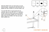
11.Securerearof lowershelfto rightsideandleft
sidepanelsusingtwo (2)1/4-20x1/2trusshead
bolts,Iockwashersandhexnuts.Handtighten
nutsonlyatthistime.
12. Lay the stand on the backside, locate two (2)
spacers, two (2) 1/4-20 x 1"truss head bolts,
Iockwashers and hex nuts. Assemble the spacers
between each of the foot assemblies and the
lower shelf on each side with one (1) truss head
bolt, Iockwasher and hex nut each as illustrated.
Hand tighten nut.
SHELF
SIDE PANEL
J
l'_ r--
SPACER
1/4-20 x 1
13.
Locate the four (4) swivel casters and sixteen
(16) 1/4-20 x 7/16 slotted truss head bolts,
Iockwashers, and hex nuts. Line up the caster
with the matching holes in lower shelf and corner
bracket (shaded area). Attach the caster with
four (4) slotted truss head bolts, Iockwashers
and hex nuts and tighten by hand as illustrated.
When all four bolts are installed use a regular
screwdriver and a 7/16" wrench or socket to
tighten securely. Repeat procedure for the three
remaining casters.
l
1/4"-20 x 7/16"
LOCKWASHER
HEX NUT

CHECKING CABINET FOR SQUARENESS
TOOLS NEEDED: Framing square, 3/4" wrench and
7/16" wrench or socket.
1. With cabinet on back side place a square on
lower shelf next to right side panel. Adjust stand
so both right side panel and lower shelf touch
square (as illustrated). Then tighten nut holding
rear of shelf to side panel and right side spacer to
front of lower shelf. Repeat procedure for left
side.
ii
2. Place square at top side of cabinet and adjust
stand so square touches both skirt and side
panel (as illustrated). Then tighten right side of
front and rear skirts to side panel. Repeat pro-
cedure for left side.
WARNING: TO AVOID INJURY FROM UNEXPECT-
ED SAW OR WORK MOVEMENT, LEVELING FEET
MUST BE ADJUSTED SO THAT SAW DOES NOT
ROCK. TO AVOID UNEXPECTED CARRIAGE MOVE-
MENT, ADJUST LEVELING FEET SO THAT THE
ARM SLOPES SLIGHTLY DOWNWARD TO THE
REAR.
3. Lift the cabinet upright onto the casters and
move to desired location. Press down on the foot
actuator pedal and lock leveling feet in "down"
position. With a 3/4 open end wrench loosen
1/2-13 hex nut. Adjust leveling feet by rotating
counterclockwise until foot lifts the front caster
off the floor - tighten 1/2-13 hex nut.
FOOT ACTUATOR
HEX NUT
LEVELING FOOT
MODEL 113.198610
16

INSTALLING DRAWERS
FOR MODEL NO. 113.198610
Tools needed: 7/16" wrench or socket, medium
screwdriver.
1. Locate one (1) front support, one (1) upper
support, and three (3) rear supports.
2. Slide the upper support into the top of the front
support so the top and side holes line up. Then
assemble to the front and rear skirts with four (4)
1/4-20 x 1/2 truss head bolts, Iockwashers, and
hex nuts. Position bolts from bottom side with
threads upwards on front skirt as illustrated.
Tighten hex nuts securely.
3. Assemble the front support to the lower support
with two (2) 1/4-20 x 1/2 truss head bolts,
Iockwashers and hex nuts. Tighten hex nuts
securely.
//
/
NOTE: It may be necessary to tilt the stand
backwards to tighten the bolts holding the center
support to the lower support.
4. Assemble a rear support to the lower support
with two (2) 1/4-20 x 1/2 truss head bolts,
Iockwashers and hex nuts. Tighten nuts securely.
Do not assemble the rear support to the upper
support at this time. These holes are used in Step
#6 to attach the stand slide bracket.
/
5. Assemble a rear support to each side panel with
four (4) 1/4-20 x 1/2 truss head bolts, lock-
washers, and hex nuts. Tighten nuts securely.
Rear support must touch lower shelf for holes to
line up with front holes.
(3
r-,-
E==
17

6. Locate the twelve (12) stand slide brackets,
twenty-four (24) truss head bolts, Iockwashers
and hex nuts. Assemble the stand slide brackets
on the rear supports and inside of the side panels
in holes as illustrated. Assemble the stand slide
brackets on the center and rear supports in holes
as illustrated starting at the top.
The rear mounting hole in the stand slide bracket
is slightly enlarged and must be mounted to the
rear support for stand slide stops to work. Tighten
nuts securely.
o_
TOp
7. Locate the twelve (12) center slide brackets and
the two (2) lubrication packets. Lubricate upper
& lower channel on all twelve (12) center slide
brackets,
NOTE: In order for drawer stops to work, the center
slide bracket must be assembled as illustrated.
Failure to do so may result in drawer sliding off slide
brackets.
8. Insert center slide brackets into the stand slide
brackets. Center slide brackets should snap over
front stop when pushed on stand slide bracket.
CABINET SLIDE BRACKETS STOP TO THIS SIDE
REAR STOP
DRAWER STOP TO THIS SIDE
9. Locate the metal drawer, drawer fronts and the
bag of drawer front push-in type fasteners. Slide
drawer fronts onto appropriate size drawer. Make
sure the drawer front tabs engage the metal
drawer edges. Align holes and install push-in
type fasteners to assemble front to metal drawer.
Be sure all fasteners clamp the drawer front
firmly to the metal drawer.
10. Set drawer assemblies aside until called for on
page 24.
/
/
18

44" CABINET ASSEMBLY
FOR MODEL NO. 113.198410
ASSEMBLE CABINET BEFORE
MOUNTING SAW
Separate all "loose" parts from packing materials
and check each item with "Parts List" to make sure
all items are accounted for before discarding any
pack_ng material.
WARNING: IF ANY PARTS ARE MISSING, DO NOT
ATTEMPT TO ASSEMBLE RADIAL ARM SAW,
PLUG IN THE POWER CORD, OR TURN THE
SWITCH ON UNTIL THE MISSING PARTS ARE
OBTAINED ARE ARE INSTALLED CORRECTLY.
44" CABINET ASSEMBLY #507490
FOR MODEL NO. 113.198410
A Right Side Panel ......................... 1
B Left Side Panel ........................... 1
C Lower Shelf .............................. 1
D Under Support ........................... 1
E Skirt ..................................... 2
F Shelf Stiffener ........................... 1
G Corner Brackets ......................... 4
H Lower Support ........................... 1
I Spacer .................................. 2
J Upper Support ........................... 1
K Front Support ............................ 1
L Door .................................... 2
AH Shelf Stiffener Rear ...................... 1
Loose Parts Bag #507533 contains the following:
M Magnetic Catch .......................... 2
N Hinge ................................... 4
O Pan Head Screw #6 x 1/2 ................. 4
P Pan Head Screw #10 x 1/2 ................ 8
Q Pan Head Screw #6-32 x 3/8 .............. 4
Loose Parts Bag #507491 contains the following:
R Truss Head Bolt 1/4-20 x 1/2 ............. 66
S Hex Nut 1/4-20 .......................... 66
T Lockwasher 1/4 ......................... 66
U Leveling Foot ............................ 4
V Hex Jam Nut 1/2-13 ...................... 8
W Pan Head Type"BT" Screw 14 x 1/2 ....... 8
X Pan Head Sheet Metal Screw #10 x 1 ...... 6
Loose Parts Bag #507532 contains the following:
Y Yoke Plug ............................... 1
Z Battery .................................. 1
AA Switch Key .............................. 1
AB Guard Pad ............................... 1
AC Plastic Plug .............................. 4
AD Mot.or Support Cap ....................... 1
AE Pan Head Screw 10-32 x 1/2 .............. 1
AF Washer Ext. #10 .......................... 1
AG Cover ................................... 2
/
G
Z AA
AC AD AE
¢
L_
jJ
AB
AF AG
19

2.Afterlayoutofstandparts,takethebottomshelf
andturnupsidedownonfloor.Smallfrontflange
shouldbepointingupward.
3. Place one shelf stiffener against front flange of
shelf as shown.
4. Place the under support on the shelf. Locate two
(2) 1/4-20 x 1/2 truss head bolts, Iockwashers
and hex nuts from loose parts bag #488. Attach
the supports to the shelf in holes as illustrated
and tighten nuts with 7/16" wrench or socket.
r
5. Locate lower support and assemble lower sup-
port, shelf and under shelf support with four (4)
1/4-20 xl/2 truss head bolts, Iockwashers, and
hex nuts.
6. Attach the second shelf stiffener to the under
support. Use two (2) 1/4-20 x 1/2 truss head
bolts, Iockwashers, and hex nuts to fasten to the
under support with 7/16" wrench or socket.
_C_J -,
7. Locate the four (4) corner brackets and use eight
(8) 1/4-20 x 1/2 truss head bolts, Iockwashers
and hex nuts to mount the corner brackets to the
shelf AS ILLUSTRATED. Tighten the nuts with a
7/16" wrench or socket.
20
/