
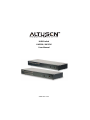
KVM Switch
KH1508 / KH1516
User Manual
www.aten.com

KH1508 / KH1516 User Manual
ii
FCC Information
This is an FCC Class A product. In a domestic environment this product may
cause radio interference in which case the user may be required to take
adequate measures.
This equipment has been tested and found to comply with the limits for a Class
A digital device, pursuant to Part 15 of the FCC Rules. These limits are
designed to provide reasonable protection against harmful interference when
the equipment is operated in a commercial environment. This equipment
generates, uses and can radiate radio frequency energy and, if not installed and
used in accordance with the instruction manual, may cause harmful
interference to radio communications. Operation of this equipment in a
residential area is likely to cause harmful interference in which case the user
will be required to correct the interference at his own expense.
RoHS
This product is RoHS compliant.
SJ/T 11364-2006
The following contains information that relates to China.

KH1508 / KH1516 User Manual
iii
User Information
Online Registration
Be sure to register your product at our online support center:
Telephone Support
For telephone support, call this number:
User Notice
All information, documentation, and specifications contained in this manual
are subject to change without prior notification by the manufacturer. The
manufacturer makes no representations or warranties, either expressed or
implied, with respect to the contents hereof and specifically disclaims any
warranties as to merchantability or fitness for any particular purpose. Any of
the manufacturer's software described in this manual is sold or licensed as is.
Should the programs prove defective following their purchase, the buyer (and
not the manufacturer, its distributor, or its dealer), assumes the entire cost of all
necessary servicing, repair and any incidental or consequential damages
resulting from any defect in the software.
The manufacturer of this system is not responsible for any radio and/or TV
interference caused by unauthorized modifications to this device. It is the
responsibility of the user to correct such interference.
The manufacturer is not responsible for any damage incurred in the operation
of this system if the correct operational voltage setting was not selected prior
to operation. PLEASE VERIFY THAT THE VOLTAGE SETTING IS
CORRECT BEFORE USE.
International http://support.aten.com
North America ATEN TECH http://www.aten-usa.com/product_registration
ATEN NJ http://support.aten.com
International 886-2-8692-6959
North America ATEN TECH 1-888-999-ATEN
ATEN NJ 1-732-356-1703

KH1508 / KH1516 User Manual
iv
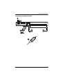
Package Contents
The KH1508 / KH1516 package consists of:
1 KH1508 or KH1516 Cat 5 High-Density KVM Switch
1 Firmware Upgrade Cable
1Power Cord
1 Rack Mount Kit
1 Foot Pad Set (4 pcs.)
1 User Manual*
1 Quick Start Guide
Check to make sure that all of the components are present and in good order.
If anything is missing, or was damaged in shipping, contact your dealer.
Read this manual thoroughly and follow the installation and operation
procedures carefully to prevent any damage to the switch or to any other
devices on the KH1508 / KH1516 installation.
* Features may have been added to the KH1508 / KH1516 since this manual
was printed. Please visit our web site to download the most up-to-date
version of the manual.
Copyright © 2008 ATEN® International Co., Ltd.
Manual Part No. PAPE-0268-3AXG
Manual Date: 2010-09-14
Altusen and the Altusen logo are registered trademarks of ATEN International Co., Ltd. All rights reserved.
All other brand names and trademarks are the registered property of their respective owners.

KH1508 / KH1516 User Manual
v
Contents
FCC Information . . . . . . . . . . . . . . . . . . . . . . . . . . . . . . . . . . . . . . . . . . . . . ii
RoHS. . . . . . . . . . . . . . . . . . . . . . . . . . . . . . . . . . . . . . . . . . . . . . . . . . . . . . ii
SJ/T 11364-2006. . . . . . . . . . . . . . . . . . . . . . . . . . . . . . . . . . . . . . . . . . . . . ii
User Information . . . . . . . . . . . . . . . . . . . . . . . . . . . . . . . . . . . . . . . . . . . . .iii
Online Registration . . . . . . . . . . . . . . . . . . . . . . . . . . . . . . . . . . . . . . . .iii
Telephone Support . . . . . . . . . . . . . . . . . . . . . . . . . . . . . . . . . . . . . . . .iii
User Notice . . . . . . . . . . . . . . . . . . . . . . . . . . . . . . . . . . . . . . . . . . . . . .iii
Package Contents. . . . . . . . . . . . . . . . . . . . . . . . . . . . . . . . . . . . . . . . . . . iv
About This Manual . . . . . . . . . . . . . . . . . . . . . . . . . . . . . . . . . . . . . . . . . .viii
Overview . . . . . . . . . . . . . . . . . . . . . . . . . . . . . . . . . . . . . . . . . . . . . . .viii
Conventions . . . . . . . . . . . . . . . . . . . . . . . . . . . . . . . . . . . . . . . . . . . . ix
Product Information. . . . . . . . . . . . . . . . . . . . . . . . . . . . . . . . . . . . . . . . . . ix
Chapter 1.
Introduction
Overview. . . . . . . . . . . . . . . . . . . . . . . . . . . . . . . . . . . . . . . . . . . . . . . . . . .1
Features . . . . . . . . . . . . . . . . . . . . . . . . . . . . . . . . . . . . . . . . . . . . . . . . . . .3
Requirements . . . . . . . . . . . . . . . . . . . . . . . . . . . . . . . . . . . . . . . . . . . . . . .4
Console . . . . . . . . . . . . . . . . . . . . . . . . . . . . . . . . . . . . . . . . . . . . . . . . .4
Computers. . . . . . . . . . . . . . . . . . . . . . . . . . . . . . . . . . . . . . . . . . . . . . .4
KVM Adapter Cables. . . . . . . . . . . . . . . . . . . . . . . . . . . . . . . . . . . . . . .4
Operating Systems . . . . . . . . . . . . . . . . . . . . . . . . . . . . . . . . . . . . . . . .5
Components . . . . . . . . . . . . . . . . . . . . . . . . . . . . . . . . . . . . . . . . . . . . . . . .6
Front View. . . . . . . . . . . . . . . . . . . . . . . . . . . . . . . . . . . . . . . . . . . . . . .6
KH1508 . . . . . . . . . . . . . . . . . . . . . . . . . . . . . . . . . . . . . . . . . . . . . .6
KH1516 . . . . . . . . . . . . . . . . . . . . . . . . . . . . . . . . . . . . . . . . . . . . . .6
Rear View . . . . . . . . . . . . . . . . . . . . . . . . . . . . . . . . . . . . . . . . . . . . . . .8
KH1508 . . . . . . . . . . . . . . . . . . . . . . . . . . . . . . . . . . . . . . . . . . . . . .8
KH1516 . . . . . . . . . . . . . . . . . . . . . . . . . . . . . . . . . . . . . . . . . . . . . .8
Chapter 2.
Hardware Setup
Overview. . . . . . . . . . . . . . . . . . . . . . . . . . . . . . . . . . . . . . . . . . . . . . . . . . .9
Before you Begin. . . . . . . . . . . . . . . . . . . . . . . . . . . . . . . . . . . . . . . . . . . . .9
Stacking and Rack Mounting . . . . . . . . . . . . . . . . . . . . . . . . . . . . . . . . . .10
Stacking. . . . . . . . . . . . . . . . . . . . . . . . . . . . . . . . . . . . . . . . . . . . . . . .10
Rack Mounting . . . . . . . . . . . . . . . . . . . . . . . . . . . . . . . . . . . . . . . . . .11
Single Station Installation . . . . . . . . . . . . . . . . . . . . . . . . . . . . . . . . . . . . .12
Daisy Chaining . . . . . . . . . . . . . . . . . . . . . . . . . . . . . . . . . . . . . . . . . . . . .15
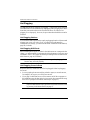
Chapter 3.
Basic Operation
Port Selection . . . . . . . . . . . . . . . . . . . . . . . . . . . . . . . . . . . . . . . . . . . . . .17
Manual. . . . . . . . . . . . . . . . . . . . . . . . . . . . . . . . . . . . . . . . . . . . . . . . .17

KH1508 / KH1516 User Manual
vi
OSD . . . . . . . . . . . . . . . . . . . . . . . . . . . . . . . . . . . . . . . . . . . . . . . . . . 17
Hotkey. . . . . . . . . . . . . . . . . . . . . . . . . . . . . . . . . . . . . . . . . . . . . . . . . 17
Hot Plugging. . . . . . . . . . . . . . . . . . . . . . . . . . . . . . . . . . . . . . . . . . . . . . . 18
Hot Plugging Stations . . . . . . . . . . . . . . . . . . . . . . . . . . . . . . . . . . . . . 18
Hot Plugging KVM Ports . . . . . . . . . . . . . . . . . . . . . . . . . . . . . . . . . . . 18
Hot Plugging Console Ports . . . . . . . . . . . . . . . . . . . . . . . . . . . . . . . .18
Powering Off and Restarting. . . . . . . . . . . . . . . . . . . . . . . . . . . . . . . . . . . 19
Port ID Numbering . . . . . . . . . . . . . . . . . . . . . . . . . . . . . . . . . . . . . . . . . .19
Chapter 4.
OSD Operation
OSD Overview . . . . . . . . . . . . . . . . . . . . . . . . . . . . . . . . . . . . . . . . . . . . .21
OSD Navigation . . . . . . . . . . . . . . . . . . . . . . . . . . . . . . . . . . . . . . . . . . . .23
OSD Main Screen Headings. . . . . . . . . . . . . . . . . . . . . . . . . . . . . . . . . . . 23
OSD Functions . . . . . . . . . . . . . . . . . . . . . . . . . . . . . . . . . . . . . . . . . . . . . 24
F1: GOTO. . . . . . . . . . . . . . . . . . . . . . . . . . . . . . . . . . . . . . . . . . . . . .24
F2: LIST . . . . . . . . . . . . . . . . . . . . . . . . . . . . . . . . . . . . . . . . . . . . . . . 25
F3: SET. . . . . . . . . . . . . . . . . . . . . . . . . . . . . . . . . . . . . . . . . . . . . . . . 26
F4: ADM . . . . . . . . . . . . . . . . . . . . . . . . . . . . . . . . . . . . . . . . . . . . . . . 28
F5: SKP. . . . . . . . . . . . . . . . . . . . . . . . . . . . . . . . . . . . . . . . . . . . . . . . 32
F6: BRC . . . . . . . . . . . . . . . . . . . . . . . . . . . . . . . . . . . . . . . . . . . . . . . 33
F7: SCAN . . . . . . . . . . . . . . . . . . . . . . . . . . . . . . . . . . . . . . . . . . . . . . 34
F8: LOUT . . . . . . . . . . . . . . . . . . . . . . . . . . . . . . . . . . . . . . . . . . . . . . 35
Chapter 5.
Keyboard Port Operation
Overview. . . . . . . . . . . . . . . . . . . . . . . . . . . . . . . . . . . . . . . . . . . . . . . . . .37
Invoking Hotkey Mode . . . . . . . . . . . . . . . . . . . . . . . . . . . . . . . . . . . . . . .37
Selecting the Active Port. . . . . . . . . . . . . . . . . . . . . . . . . . . . . . . . . . . . . . 38
Auto Scanning . . . . . . . . . . . . . . . . . . . . . . . . . . . . . . . . . . . . . . . . . . . . . 38
Setting the Scan Interval. . . . . . . . . . . . . . . . . . . . . . . . . . . . . . . . . . . 38
Invoking Auto Scan. . . . . . . . . . . . . . . . . . . . . . . . . . . . . . . . . . . . . . . 39
Skip Mode. . . . . . . . . . . . . . . . . . . . . . . . . . . . . . . . . . . . . . . . . . . . . . . . .40
Hotkey Beeper Control . . . . . . . . . . . . . . . . . . . . . . . . . . . . . . . . . . . . . . .40
Hotkey Summary Table . . . . . . . . . . . . . . . . . . . . . . . . . . . . . . . . . . . . . . 41
Chapter 6.
Keyboard Emulation
Mac Keyboard. . . . . . . . . . . . . . . . . . . . . . . . . . . . . . . . . . . . . . . . . . . . . .43
Sun Keyboard. . . . . . . . . . . . . . . . . . . . . . . . . . . . . . . . . . . . . . . . . . . . . . 44
Chapter 7.
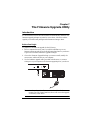
The Firmware Upgrade Utility
Introduction. . . . . . . . . . . . . . . . . . . . . . . . . . . . . . . . . . . . . . . . . . . . . . . .45
Before You Begin . . . . . . . . . . . . . . . . . . . . . . . . . . . . . . . . . . . . . . . . 45
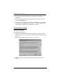
Performing the Upgrade . . . . . . . . . . . . . . . . . . . . . . . . . . . . . . . . . . . 46

KH1508 / KH1516 User Manual
vii
Starting the Upgrade . . . . . . . . . . . . . . . . . . . . . . . . . . . . . . . . . . .46
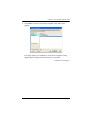
Upgrade Succeeded . . . . . . . . . . . . . . . . . . . . . . . . . . . . . . . . . . .49
Upgrade Failed . . . . . . . . . . . . . . . . . . . . . . . . . . . . . . . . . . . . . . .49
Firmware Upgrade Recovery . . . . . . . . . . . . . . . . . . . . . . . . . . . . . . .50
Adapter Cable Upgrade . . . . . . . . . . . . . . . . . . . . . . . . . . . . . . . . . . . . . .51
Introduction . . . . . . . . . . . . . . . . . . . . . . . . . . . . . . . . . . . . . . . . . . . . .51
Before You Begin . . . . . . . . . . . . . . . . . . . . . . . . . . . . . . . . . . . . . . . .51
Performing the Upgrade . . . . . . . . . . . . . . . . . . . . . . . . . . . . . . . . . . .52
Starting the Upgrade . . . . . . . . . . . . . . . . . . . . . . . . . . . . . . . . . . .52
Upgrade Succeeded . . . . . . . . . . . . . . . . . . . . . . . . . . . . . . . . . . .53
Adapter Cable Firmware Upgrade Recovery . . . . . . . . . . . . . . . . . . .54
Appendix
Safety Instructions. . . . . . . . . . . . . . . . . . . . . . . . . . . . . . . . . . . . . . . . . . .55
General . . . . . . . . . . . . . . . . . . . . . . . . . . . . . . . . . . . . . . . . . . . . . . . .55
Rack Mounting . . . . . . . . . . . . . . . . . . . . . . . . . . . . . . . . . . . . . . . . . .57
Technical Support. . . . . . . . . . . . . . . . . . . . . . . . . . . . . . . . . . . . . . . . . . .58
International. . . . . . . . . . . . . . . . . . . . . . . . . . . . . . . . . . . . . . . . . . . . .58
North America . . . . . . . . . . . . . . . . . . . . . . . . . . . . . . . . . . . . . . . . . . .58
Specifications . . . . . . . . . . . . . . . . . . . . . . . . . . . . . . . . . . . . . . . . . . . . . .59
Connection Tables . . . . . . . . . . . . . . . . . . . . . . . . . . . . . . . . . . . . . . . . . .60
KH1508 . . . . . . . . . . . . . . . . . . . . . . . . . . . . . . . . . . . . . . . . . . . . . . . .60
KH1516 . . . . . . . . . . . . . . . . . . . . . . . . . . . . . . . . . . . . . . . . . . . . . . . .60
OSD Factory Default Settings. . . . . . . . . . . . . . . . . . . . . . . . . . . . . . . . . .61
Administrator Login Failure. . . . . . . . . . . . . . . . . . . . . . . . . . . . . . . . . . . .62
Troubleshooting . . . . . . . . . . . . . . . . . . . . . . . . . . . . . . . . . . . . . . . . . . . .63
Overview . . . . . . . . . . . . . . . . . . . . . . . . . . . . . . . . . . . . . . . . . . . . . . .63
User Manual Corrections . . . . . . . . . . . . . . . . . . . . . . . . . . . . . . . . . . . . .64
Limited Warranty. . . . . . . . . . . . . . . . . . . . . . . . . . . . . . . . . . . . . . . . . . . .65

KH1508 / KH1516 User Manual
viii
About This Manual
This User Manual is provided to help you get the most from your KH1508 /
KH1516 system. It covers all aspects of installation, configuration and
operation. An overview of the information found in the manual is provided
below.
Overview
Chapter 1, Introduction, introduces you to the KH1508 / KH1516 system.
Its purpose, features and benefits are presented, and its front and back panel
components are described.
Chapter 2, Hardware Setup, describes how to set up your installation. The
necessary steps – from a basic single stage hookup to a complete 32 switch
daisy chained operation are provided.
Chapter 3, Basic Operation, explains the fundamental concepts involved
in operating the KH1508 / KH1516.
Chapter 4, OSD Operation, provides a complete description of the
KH1508 / KH1516's OSD (On Screen Display), and how to work with it.
Chapter 5, Keyboard Port Operation, details all of the concepts and
procedures involved in the keyboard hotkey operation of your KH1508 /
KH1516 installation.
Chapter 6, Keyboard Emulation, provides tables that list the PC to Mac
and PC to Sun keyboard emulation mappings.
Chapter 7, The Firmware Upgrade Utility, explains how to upgrade the
KH1508 / KH1516's firmware with the latest available versions.
An Appendix, provides specifications and other technical information
regarding the KH1508 / KH1516.

KH1508 / KH1516 User Manual
ix
Conventions
This manual uses the following conventions:
Product Information
For information about all ALTUSEN products and how they can help you
connect without limits, visit ALTUSEN on the Web or contact an ALTUSEN
Authorized Reseller. Visit ALTUSEN on the Web for a list of locations and
telephone numbers:
Monospaced Indicates text that you should key in.
[ ] Indicates keys you should press. For example, [Enter]
means to press the Enter key. If keys need to be chorded,
they appear together in the same bracket with a plus sign
between them: [Ctrl+Alt].
1. Numbered lists represent procedures with sequential steps.
♦ Bullet lists provide information, but do not involve sequential
steps.
→ Indicates selecting the option (on a menu or dialog box, for
example), that comes next. For example, Start → Run means
to open the Start menu, and then select Run.
Indicates critical information.
International http://www.aten.com
North America ATEN TECH http://www.aten-usa.com
ATEN NJ http://www.aten.com

KH1508 / KH1516 User Manual
x
This Page Intentionally Left Blank

1
Chapter 1
Introduction
Overview
KH1508 / KH1516 KVM switches are control units that allow access to
multiple computers from a single KVM (keyboard, monitor, and mouse)
console.
A single KH1508 / KH1516 can control up to 8 / 16 computers. As many as 31
additional KH1508 / KH1516 switches can be daisy chained from the original
unit, so that up to 512 computers can all be controlled from the original KVM
console.
Note: ATEN ACS1208 / ACS1216 switches can also be installed on a
KH1508 / KH1516 daisy chain.
A custom ASIC (patent pending) provides an auto-sensing function that
recognizes the position of each station on the chain, eliminating the need to
manually set the position with DIP switches. A seven-segment front panel LED
displays each Station's position for easy identification.
The switches feature RJ-45 connectors and use CAT 5e cable to link to the
computers. Combined with Auto Signal Compensation (ASC), 1280 x 1024 @
60 Hz signals can travel up to 40 m (130 feet) – eliminating the need for KVM
extenders. Utilizing PS/2 and USB KVM adapter cables for the final linkup, the
KH1508 / KH1516 permits any combination of PCs, Macs, Sun computers,
and serial devices to coexist on the installation.
Your KH1508 / KH1516 investment is protected by a Firmware Upgrade
Utility. You can stay current with the latest improvements in functionality by
downloading firmware update files from our website, and using the utility to
quickly and conveniently install them.
Setting up the KH1508 / KH1516 is fast and easy; plugging cables into their
appropriate ports is all that is entailed. Because the KH1508 / KH1516
intercepts keyboard and mouse input directly, there is no software to configure;
no need to get involved in complex installation routines; no need to be
concerned with incompatibility problems.

KH1508 / KH1516 User Manual
2
Access to any computer on the installation is easily accomplished – either by
pressing front panel port selection switches; entering hotkey combinations
from the keyboard; or by means of a powerful menu driven OSD system.
A convenient Auto Scan function also permits automatic scanning and one-by-
one monitoring of the activities of selected computers.
There is no better way to save time and money than with a KH1508 / KH1516
installation. By allowing a single console to manage up to 512 computers, a
KH1508 / KH1516 installation: (1) eliminates the expense of having to
purchase a separate keyboard, monitor, and mouse for each; (2) saves all the
space those extra components would take up; (3) saves on energy costs; and (4)
eliminates the inconvenience and wasted effort involved in constantly moving
from one computer to another.

Chapter 1. Introduction
3
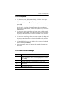
Features
A single console controls up to 8 (KH1508) or 16 (KH1516) computers
Dedicated chain ports – daisy chain up to 31 additional units – control up
to 512 computers from a single console
Extends the distance between computers and switch – up to 30 m
(100 feet) for resolutions of 1600 x 1200 @ 60 Hz; up to 40 m (130
feet)
for resolutions of 1280 x 1024 @ 60 Hz
Custom ASIC (patent pending) auto-senses station's position on daisy
chained installations – no need for manual DIP switch setting – front panel
LED indicates station's position
Multiplatform support: PC, Mac, Sun and terminal-based systems
No software required – convenient computer selection via port selection
switches, Hotkeys and intuitive on-screen display (OSD) menus
Auto Scan feature for monitoring user-selected computers
Hot Pluggable – add or remove switches/computers without having to
power down the switches
Two level password security – only authorized users view and control the
computers – up to four Users plus an Administrator with separate profiles
for each
Two level logout – Manual and Timed
PS/2 keyboard and mouse emulation – computers boot even when the
console focus is elsewhere
Superior video quality – supports resolutions up to 1600 x 1200 @ 60 Hz;
DDC2B
Multi-language keyboard support: English (US / UK); French; German;
Japanese; Korean; Traditional Chinese
Rack mountable in 19" System Rack (1U)

KH1508 / KH1516 User Manual
4
Requirements
Console
A VGA, SVGA, or multisync monitor capable of the highest resolution
that you will be using on any computer in the installation
A PS/2 style mouse
A PS/2 style keyboard
Computers
The following equipment must be installed on the computers that connect to the
KH1508 or KH1516 KVM ports:
A VGA, SVGA or multisync port
A Type A USB port and USB host controller (for USB KVM adapter cable
connection, see below)
6-pin Mini-DIN keyboard and mouse ports (for PS/2 KVM adapter cable
connection, see below)
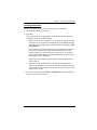
KVM Adapter Cables
Cat 5e cable is required to connect the KH1508 / KH1516 to one of the
KVM adapter cables.
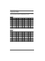
The following KVM adapter cables are required for use with the KH1508 /
KH1516:
Note: KVM adapter cables are referred to as I/O Modules in some dialog
boxes.
Function Module
Connect to devices with PS/2 ports KA9520
Connect to devices with USB ports KA9570
Connect to Sun Legacy systems (with 13W3 port) KA9130
Connect to Sun USB systems KA9131
Connect to serial based devices KA9140

Chapter 1. Introduction
5
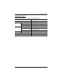
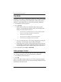
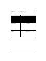
Operating Systems
Supported operating systems are shown in the table, below:
OS Version
Windows 95 and higher
Linux RedHat 6.0 and higher
SuSE 8.2 and higher
Mandriva (Mandrake) 9.0 and higher
UNIX AIX 4.3 and higher
FreeBSD 3.51 and higher
Sun Solaris 8 and higher
Novell Netware 5.0 and higher
OS/2 Warp and higher
DOS 6.2 and higher

KH1508 / KH1516 User Manual
6
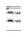
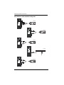
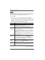
Components
Front View
KH1508
KH1516
43 5
1&2
67
1&2
4
3567

Chapter 1. Introduction
7
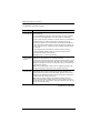
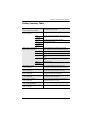
No. Component Description
1 Port Selection
Switches
Press a switch to give the KVM focus to the computer
attached to its corresponding port.
Simultaneously pressing Buttons 1 and 2 for 3 seconds
performs a keyboard and mouse reset.
Simultaneously pressing Buttons 7 and 8 starts Auto Scan
mode.
2 Port LEDs The Port LEDs are built into the Port Selection Switches. The
left ones are the On Line LEDs; the right ones are the
Selected Port LEDs:
An On Line LED lights GREEN to indicate that the computer
attached to its corresponding port is up and running. A
flashing LED indicates that the Port is being used for
cascading to another switch.
A Selected LED lights ORANGE to indicate that the
computer attached to its corresponding port is the one that
has the KVM focus. The LED is steady under normal
conditions, but flashes when its port is accessed under Auto
Scan mode.
3 Reset Switch Pressing this switch in performs a system reset.
Note: The switch is recessed and must be pushed with a
small object, such as the end of a paper clip, or a ballpoint
pen.
4 Firmware
Upgrade
Recovery
Switch
During normal operation and while performing a firmware
upgrade, this switch should be in the NORMAL position. If a
firmware upgrade operation does not complete successfully,
this switch is used to perform a firmware upgrade recovery.
See Firmware Upgrade Recovery, page 50 for details.
5 Firmware
Upgrade Port
The Firmware Upgrade Cable that transfers the firmware
upgrade data from the administrator's computer to the
KH1508 / KH1516 (see page 45), plugs into this RJ-11
connector.
6 Power LED Lights to indicate that the KH1508 / KH1516 is powered and
ready to operate.
7 Station ID LED The KH1508 / KH1516's Station ID is displayed here. If this is
a single station installation (see page 12), or the first station on
a daisy chained installation (see page 15), the KH1508 /
KH1516 has a station ID of 01.
On a daisy chained installation, the KH1508 / KH1516 auto-
senses its position and displays the station ID that
corresponds to its place in the chain. (see Port ID Numbering,
page 19, for details).

KH1508 / KH1516 User Manual
8
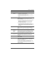
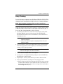
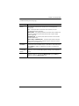
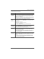
Rear View
KH1508
KH1516
No. Component Description
1 Power Socket The power cord to the AC source plugs in here.
2 Power Switch This is a standard rocker switch that powers the KH1508 /
KH1516 on and off.
3 Daisy Chain
Ports
When daisy chaining units (see Daisy-chaining, page 15), the
daisy chain cables plug in here. The port on the left is the
Chain In port; the port on the right is the Chain Out port.
4 Local Console
Port Section
If this is a single station installation, or if this is the first station
of a daisy chained installation, the keyboard, monitor, and
mouse that make up the local console plug in here.
5 KVM Port
Section
The Cat 5 cables that link to the KVM adapter cables (which
link to the computers) plug in here.
12 3
45
12
54
3

9
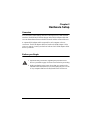
Chapter 2
Hardware Setup
Overview
For convenience and flexibility that allows mixing the PS/2, USB and serial
interfaces, the KH1508 / KH1516's design utilizes KVM adapter cables that
serve as intermediaries between the KVM switch and the connected devices:
A separate KVM adapter cable is required for each computer or device
connection. The KVM adapter cables are listed in the KVM Adapter Cables
section on page 4. Consult your dealer to find out which KVM adapter cables
best fit your needs.
Before you Begin
1. Important safety information regarding the placement of this
device is provided on page 55. Please review it before proceeding.
2. Make sure that the power to any device that you connect to the
installation has been turned off. You m
ust unplug the power cords
of any computers that have the Keyboard Power On function.

KH1508 / KH1516 User Manual
10
Stacking and Rack Mounting
The KH1508 / KH1516 can be stacked on the desktop or rack mounted at the
front or rear of the rack. The following sections take you through the
procedures for each method.
Note: 1. Allow at least 5.1 cm on each side for adequate ventilation and
12.7 cm at the rear for power cord and cable clearance.
2. The standard rack mount kit does not include rack mount screws or
cage nuts. If you need additional rack mount screws or cage nuts,
contact your rack dealer.
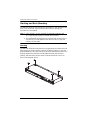
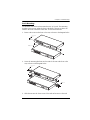
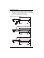
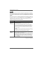
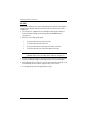
Stacking
The KH1508 / KH1516 can be placed on any appropriate level surface that can
safely support its weight plus the weight of its attached cables. To place the
KH1508 / KH1516, or to stack units if you are daisy chaining them, remove the
backing material from the bottom of the rubber feet that came with this
package, and stick them onto the switch’s bottom panel at the corners, as
shown in the diagram, below:
Page is loading ...
Page is loading ...
Page is loading ...
Page is loading ...
Page is loading ...
Page is loading ...
Page is loading ...
Page is loading ...
Page is loading ...
Page is loading ...
Page is loading ...
Page is loading ...
Page is loading ...
Page is loading ...
Page is loading ...
Page is loading ...
Page is loading ...
Page is loading ...
Page is loading ...
Page is loading ...
Page is loading ...
Page is loading ...
Page is loading ...
Page is loading ...
Page is loading ...
Page is loading ...
Page is loading ...
Page is loading ...
Page is loading ...
Page is loading ...
Page is loading ...
Page is loading ...
Page is loading ...
Page is loading ...
Page is loading ...
Page is loading ...
Page is loading ...
Page is loading ...
Page is loading ...
Page is loading ...
Page is loading ...
Page is loading ...
Page is loading ...
Page is loading ...
Page is loading ...
Page is loading ...
Page is loading ...
Page is loading ...
Page is loading ...
Page is loading ...
Page is loading ...
Page is loading ...
Page is loading ...
Page is loading ...
Page is loading ...
Page is loading ...
Page is loading ...
Page is loading ...
-
 1
1
-
 2
2
-
 3
3
-
 4
4
-
 5
5
-
 6
6
-
 7
7
-
 8
8
-
 9
9
-
 10
10
-
 11
11
-
 12
12
-
 13
13
-
 14
14
-
 15
15
-
 16
16
-
 17
17
-
 18
18
-
 19
19
-
 20
20
-
 21
21
-
 22
22
-
 23
23
-
 24
24
-
 25
25
-
 26
26
-
 27
27
-
 28
28
-
 29
29
-
 30
30
-
 31
31
-
 32
32
-
 33
33
-
 34
34
-
 35
35
-
 36
36
-
 37
37
-
 38
38
-
 39
39
-
 40
40
-
 41
41
-
 42
42
-
 43
43
-
 44
44
-
 45
45
-
 46
46
-
 47
47
-
 48
48
-
 49
49
-
 50
50
-
 51
51
-
 52
52
-
 53
53
-
 54
54
-
 55
55
-
 56
56
-
 57
57
-
 58
58
-
 59
59
-
 60
60
-
 61
61
-
 62
62
-
 63
63
-
 64
64
-
 65
65
-
 66
66
-
 67
67
-
 68
68
-
 69
69
-
 70
70
-
 71
71
-
 72
72
-
 73
73
-
 74
74
-
 75
75
-
 76
76
-
 77
77
-
 78
78


Ask a question and I''ll find the answer in the document
Finding information in a document is now easier with AI
Related papers
Other documents
-
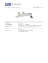 Cables Direct KVM-512RK Datasheet
-
 KinAn LD2716 Owner's manual
-
 KinAn LH2708 Owner's manual
-
Altusen ALTUSEN KH1508 User manual
-
Zonet KVM3332 Installation guide
-
-
ATEN Technology ALTUSEN KH1516 User manual
-
 Shenzhen Kinan Technology KC2132i User manual
-
Tripp Lite KVM B005-008 User manual
-
 KinAn KC2108 Owner's manual


