Bosch WTVC3300US/09 Owner's manual
- Category
- Electric laundry dryers
- Type
- Owner's manual
This manual is also suitable for

osch Vision _ 300/500/800 Series
Electric Clothes Dryers

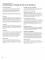
Features and Benefits of Your New Dryer
ActiveDry TM Technology
Moisture and temperature levels are constantly monitored to
ensure precise drying results for a wide array of fabrics.
Everything from T shirts to baby blankets comes out warm
and soft every time.
Constant monitoring ensures the lowest energy usage
possible, cutting consumption by up to 50% per year.
EcoSmart TI_4
EcoSmart Tt_4 technology utilizes a network of sensors in the
Bosch Vision dryer for cycles that conserve the most energy
possible while maintaining superior drying performance. By
adjusting to how wet the load is and regulating temperature
to never over heat, it is no wonder that Bosch offers some of
the most efficient dryers in the market.
EcoAction TM
This option gives you the ability to reduce energy usage by
up to 10%. By selecting this option, temperature is reduced
to save resources while the cycle time is slightly extended to
ensure proper drying.
DynamicAir TI_4
The Bosch Vision DynamicAir TM system features gentle heat
and high air volume in the most gentle dryer drum. Only
Bosch Vision can offer a one-piece dryer drum with a
backshield full of holes to properly distribute air over your
laundry, giving you the most gentle and effective drying
possible.
Wrinkle Block®
Sometimes you can't get your laundry right when the buzzer
rings. Wrinkle Block® gives you one hour of intermittent
tumbling, preventing creases from setting in and, ultimately,
reducing ironing time.
Stainless Steel Drum
Bosch dryers feature smooth, stainless steel drums for the
gentlest of care.
160 ° Door Hinge
The dryer door opens up to 160° - making it easier to load
and unload laundry. Washer and dryer doors also open in
opposite directions, so when set up side by side,
transferring your damp laundry to the dryer becomes an
effortless task.
Quiet Performance
Bosch laundry appliances use brushless motors,
suspended pump systems, and special sound-deadening
material to keep them exceptionally quiet while in operation.
Quiet operation means they can be installed virtually
anywhere in the home without causing a disturbance.
Dryer Rack
The dryer rack protects the most delicate fabrics or a pair of
tennis shoes, allowing either to drywithout tumbling. It is
standard on the Premium model and is available as an
accessory on all models.
Lint Filter
The dryer lint filter is conveniently located in the appliance
housing below the dryer door for easy access. The lint
filter's fine mesh filter captures even the smallest lint
particles. And to increase drying efficiency, there's also a
lint filter LED on the control panel that illuminates should the
filter need immediate cleaning.
Steam Cycles
Steam Cycles offered on select models utilize added
moisture to help relax fabric, ease wrinkling, and freshen
cotton blend laundry items to reduce odor.

Table of Contents
Definitions ..........................................................................................
IMPORTANT SAFETY INSTRUCTIONS .................................................................
GROUNDING INSTRUCTIONS .......................................................................
INSTALLATION INSTRUCTIONS .......................................................................
Introduction .......................................................................................
Information concerning waste disposal ................................................................
Before installing the dryer ............................................................................
Checklist for Installation .............................................................................
Installation Location ................................................................................
Dryer Dimensions ..................................................................................
Door Hinge Reversal ................................................................................
Installation Types ...................................................................................
Electrical connection ...............................................................................
Exhaust air connection ..............................................................................
Accessories .......................................................................................
Preparing to transport the dryer - step by step ..........................................................
OPERATING INSTRUCTIONS .........................................................................
Panel ............................................................................................
Additional Safety information .........................................................................
Protection of the environment .........................................................................
Laundry ............................................................................................
Identification of fabrics ..............................................................................
Drying tips ........................................................................................
Cycle Selection ......................................................................................
Options (Delicates, ECO Action) ......................................................................
LED indicators of cycle sequence .....................................................................
Cycle Selection Table ...............................................................................
Automatic cycles ...................................................................................
Steam cycles ......................................................................................
Special cycles .....................................................................................
Time cycles .......................................................................................
Additional Options on LCD Menu .....................................................................
Operation ...........................................................................................
Using the dryer ....................................................................................
Cleaning the lint filter ................................................................................
Using the dryer rack (Option) .........................................................................
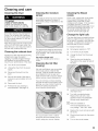
Cleaning and care ...................................................................................
Cleaning the dryer ..................................................................................
Cleaning the exhaust duct ...........................................................................
Cleaning the moisture sensor ........................................................................
Cleaning the lint filter housing ........................................................................
Cleaning the Steam nozzle ..........................................................................
Change the light bulb ...............................................................................
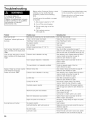
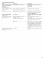
Troubleshooting .....................................................................................
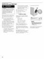
SERVICE and REPAIR ..............................................................................
STATEMENT OF LIMITED PRODUCT WARRANTY ......................................................
4
5
6
7
7
7
7
8
8
8
9
11
14
17
19
19
20
20
21
21
21
21
21
22
22
23
24
24
24
24
24
24
26
26
27
28
29
29
29
29
29
29
29
30
32
33
3

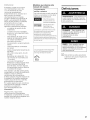
Congratulations!
Your new clothes dryer is a modern,
high quality domestic appliance.
This dryer complies with:
UL 2158/CAN/CSA-C22.2 No.
112 97 Clothes Dryers
A distinctive feature of your dryer is low
energy consumption.
An easy operation philosophy, a variety
of customized drying programs, and a
solid touch and feel make this
appliance a user-friendly assistant in
your household.
Bosch dryers offer the following
standard features:
High efficiency precision drying
system
Large stainless steel drum with a
capacity of up to 17.6 Ibs (8 kg)
Large port hole (16"/406 mm), and
door interlock with automatic drum
stop function
Exceptionally quiet operation
Sensor-controlled auto cycles
Timed cycles
300 and 500 Series Dryer: 20, 40
and 60 minute cycles
800 Series Dryer: 10 to
150 minutes (in increments of 10
minutes)
Wrinkle Block® feature tumbles
clothes periodically for up to one
hour following drying to help
decrease wrinkling
Each dryer which leaves our factory
has undergone a thorough
performance test and is in full working
condition. If you have any questions,
especially concerning installation of the
dryer - our customer service team will
be happy to assist you.
Further information and a selection of
our products can be found on our web
site:
www.boschappliances.com
Information
Please read and follow these operating
and installation instructions and all
other information enclosed with the
dryer.
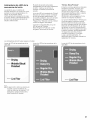
Models Covered by this User
Manual
Display types
The instructions in this manual
refer to dryers with two different
display types.
300 and 500 Series
dryers have an LED
display
800 Series dryers
................. have an LCD display
Installation, operating and
maintenance instructions are the
same for dryers with either display
type except where noted. LCD
dryer menu operation and related
options are described in the 800
Series Additional Options section
of this manual.
Steam Dryers
Steam Cycles are available on
500 and 800 Series Dryers with
the Steam logo on the panel.
Steam
Definitions
WARNING - This indicates that
death or serious injuries may
occur as a result of
non-observance of this warning.
CAUTION- This indicates that
minor or moderate injuries may
occur as a result of
non-observance of this warning.
NOTICE - This indicates that
damage to the appliance or
property may occur as a result of
non-observance of this warning.
D This symbol is used to draw the
user's attention to important
information.
4

,/k IMPORTANT SAFETY INSTRUCTIONS
The warnings and safety
instructions in this manual can not
cover all possible risks, conditions
and situations that may arise. Use
common sense and exercise
caution when installing, maintaining
and operating this or any other
appliance.
To reduce the risk of fire, electric
shock, serious injury or death to
persons and/or damage when
using your dryer, follow basic
precautions, _ncluding the
following.
1. Read all instructions before using
the dryer. Bosch dryers are
provided with Operating, Care and
Installation Instructions.
2. Do not dry articles that have been
previously cleaned, washed,
soaked or spotted with gasoline,
dry cleaning solvents, or other
flammable or explosive
substances as they give off vapors
that could ignite or explode.
To reduce the risk of fire, clothes,
cleaning rags, mop heads and the
like which have traces of any
flammable substance, such as
vegetable oil, cooking oil,
petroleum-based oils or distillates,
waxes, fats, etc., must not be
placed in the dryer. These items
may contain some flammable
substance(s), even after washing,
which may smoke or catch fire by
themselves.
5. Do not allow children to play on or
in the appliance at any time;
severe injury or death could
result. Children should be kept a
safe distance away from
appliances at all times. Children
should only be permitted within an
appliance's vicinity if under close,
constant adult supervision.
6. Do not allow children's toys, or
other items that might encourage
children to climb on the dryer, to
be stored on or in the dryer or on
shelves or in cabinets or other
storage areas adjacent to the
dryer.
7. Do not sit or stand on the top of
the dryer.
8. Do not allow anyone to climb, lean
or hang on any part of the dryer
including any protruding
components such as the
appliance door or a pullout shelf.
9. To reduce the risk of poisoning or
chemical burns, keep all cleaning
products out of the reach of
children.
10.
11.
12.
Store all laundry chemicals and
aids in a cool dry place according
to the manufacturer's instructions.
Make sure children cannot reach
them. Gasoline, combustible
materials and materials that
produce flammable vapors,
flammable liquids, and substances
that pose a fire hazard must not be
stored near the dryer.
Keep pets away from the dryer.
BEFORE THE APPLIANCE IS
REMOVED FROM SERVICE OR
DISCARDED, REMOVE THE
DOOR TO THE DRYING
COMPARTMENT.
Do not place items exposed to
cooking oils in your dryer. Items
contaminated with cooking oils
may contribute to a chemical
reaction that could cause a
laundry load to catch fire.
3. The dryer must only be used for its
intended purpose.
Do not reach into the appliance if
the drum is rotating.
Do not install or store this
appliance where it will be exposed
to the weather or the elements,
such as water/moisture, dirt,
corrosive/salt air, and excessive
cold.
4. When children become old
enough to operate the appliance, it
is the responsibility of the parents
or legal guardians to ensure that
they are instructed in safe
practices by qualified persons.
15. Do not tamper with the controls.
16. Do not repair or replace any part of
the appliance or attempt any
service unless specifically
recommended inthe
user-maintenance instructions or
in published user repair
instructions that you understand
and have the skills to carry out.
17.
18.
Do not use fabric softeners or
products to eliminate static unless
recommended by the fabric
manufacturer.
Do not use heat to dry articles
containing foam rubber (may be
labeled latex foam) or similarly
textured rubber-like materials.
Foam rubber materials can ignite
by spontaneous combustion.
19.
Do not dry articles containing
spunbonded olefin. Spunbonded
olefin can melt and can ignite by
spontaneous combustion.
20. Check the lint screen before each
laundry load and clean as needed.
Excess lint buildup can damage
the dryer and create a potential
fire hazard.
21.
Keep area around the exhaust
opening and adjacent surrounding
areas free from the accumulation
of lint, dust and dirt. An obstructed
port might reduce the airflow and
cause overheating.
22. The interior of the machine and
exhaust duct should be cleaned
periodically by qualified service
personnel.
23. Removing any panel or cover,
including the light cover, may
expose live electrical circuits.
Always be sure to unplug the dryer
from the electrical supply before
attempting any service.
Disconnect the power cord by
grasping the plug, not the cord.
24. To avoid fire hazards, do not use
an extension cord, an adapter, or
any other non-manufacturer
supplied electrical connector or
cord, to connect the dryer to the
electrical supply. Dryers require
substantial amounts of electrical
power and must have dedicated
electrical outlets.
25. Always check clothing pockets
and shake out all laundry items
before placing into dryer;
5

inappropriate objects can damage
the dryer and certain items like
cigarette lighters can pose a fire
hazard.
26. To reduce the risk of fire and
electrical shock hazards, do not
use the dryer ifthe power cord is
frayed or damaged, or if the plugs
are loose.
27. Do not operate the dryer ifany
guards and/or panels have been
removed or if any parts are missing
or broken.
28. Do not bypass any safety devices.
29. Do not use a plastic or non-metal
flexible duct with this dryer. Plastic
or non-metal flexible duct isa
potential fire hazard.
30. Do not operate this dryer until you
are sure that the dryer has been
installed according to the
INSTALLATION INSTRUCTIONS
and that installation and electrical
grounding are in compliance with
all local regulations and/or other
applicable regulations and
requirements.
31. Failure to install, maintain and/or
operate the dryer according to
the manufacturer's instructions
may result in injury and/or
damage.
32. To avoid floor damage and mold
growth, do not let spills or
splashout to cause standing water
around or under the appliance.
33. Make sure that all water
connections to the dryer have a
shut off valve that is readily
accessible. Close the appliance
water shut-off valve(s) at the end
of each day of use.
34. Check the fill hose connections on
a regular basis to ensure that they
are tight and not leaking.
Notes:
A
B
C
The IMPORTANT
SAFEGUARDS and
WARNINGS presented in this
manual do not cover all
possible conditions that may
OCCUr.
Common sense, caution and
care must be exercised when
installing, maintaining or
operating the dryer.
Always contact your dealer,
distributor, service agent or
the manufacturer about any
problems or conditions that
you do not understand.
Follow the Safety Information
provided in the
INSTALLATION
INSTRUCTIONS and the
OPERATING
INSTRUCTIONS.
GROUNDING
INSTRUCTIONS
This appliance must be grounded. In
the event of malfunction or breakdown,
grounding will reduce the risk of electric
shock by providing a path of least
resistance for the electric current.
For U.S.A.
Your dryer comes without a power
supply cord. The power cord must
meet the following requirements:
UL listed in the USA
208 - 240 volt rated (minimum)
30 amps
Type SRDT or DRT (UL 2158)
Five feet long (minimum)
Improper connection of the
equipment grounding conductor
can result in a risk of electric
shock.
Check with a qualified electrician
or service person if you are in
doubt as to whether the dryer is
_Doperlygrounded.
NOT modify the plug
provided with the appliance.
If it will not fit the outlet, have
a proper outlet installed by
a qualified electrician.
KEEP THESE
INSTRUCTIONS FOR
FUTURE REFERENCE.
In case of change of ownership, this
manual should be conveyed with the
dryer.
SAVE THESE
INSTRUCTIONS

INSTALLATION INSTRUCTIONS
Introduction
Read these installation instructions
completely and carefully. They will save
you time and effort and help to ensure
optimum dryer performance. Be sure to
observe all listed warnings and
cautions.
WARNING - Risk of Fire.
Clothes dryer installation must be
performed by a qualified installer.
Install the clothes dryer according
to the manufacturer's instructions
and local codes.
Do not install a clothes dryer with
flexible plastic venting materials. If
flexible metal (foiltype) duct is
installed, it must be of a specific
type identified by the appliance
manufacturer as suitable for
clothes dryers. Flexible venting
materials are known to collapse,
be easily crushed and trap lint.
These conditions will obstruct
clothes dryer airflow and increase
the risk of fire.
To reduce the risk of severe injury
or death, follow all installation
instructions.
SAVE THESE INSTRUCTIONS.
Inaddition to these instructions the
dryer must be installed in accordance
with all local codes or, in the absence
of a local code:
In the U.S.A., in accordance with
the National Electric Code,
ANSI/NFPA70 -latest
edition/State and Municipal codes
and/or local codes.
Information concerning
waste disposal
Disposal of the packaging
Keep children away from the
shipping carton and packaging
componentsto avoid risk of
suffocation.
All packaging materials are
environmentally friendly and can be
reused. Please dispose of packaging in
an environmentally friendly manner.
Please ask your dealer or inquire at
your local authority about the best
means of disposal.
Disposal of the old appliance
If the appliance is no longer
usable, pull out main plug, cut off
power cord and discard with
main plug. To prevent children
from locking themselves in the
appliance, remove the door.
Old appliances are not worthless
rubbish! Valuable raw materials can be
reclaimed from environmentally friendly
recycling.
Please ask your dealer or inquire at
your local authority about the best
means of disposal.
Before installing the dryer
Before installing the dryer to a
previously used ductwork system,
make sure the system is clean.
Professional ductwork cleaning is
recommended annually and also when
attaching your dryer to a previously
used ductwork system.
Maintaining clean ductwork will reduce
drying time and will improve drying
performance.
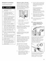
Unpacking the appliance
The dryer is very heavy, Do not
lift it by yourself. Do not lift the
appliance by projecting
components (e.g. door) - due to
risk of breakage.
Remove the appliance
packaging carefully to prevent
damage to appliance surfaces
and adjacent areas.
Check the dryer for transportation
damage. Do not install a dryer which is
visibly damaged. If in doubt, contact
your dealer.
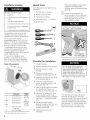
Supplied components
The dryer is supplied without
a power cord. Thepower cord
must be connectedby a qualifed
technician or a licensed
electrician.
After removing the packaging,
immediately remove any objects
from the drum.
7

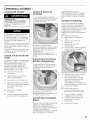
Installation location
DO NOT install the dryer:
outdoors
in an environment with dripping
water,
near flammable materials,
in rooms which are at risk of frost,
in rooms which may contain gas
or other fuels,
in cupboards with Iockable doors.
The installation room must be well
ventilated, otherwise the dryer will
operate below optimum performance.
Do not operate the dryer at
temperatures above 104°F (40°C) or
below 41 °F (5°C). Low temperatures
affect the automatic program sequence
and may prolong the drying times.
The installation surface for the dryer
must be clean, level and firm. Do not
install the appliance on carpets!
Compensate for uneven floors with the
height-adjustable feet.
The size of the installation area
depends on the dimensions of the
dryer. Ensure that there is adequate
room for the swivel range of the door!
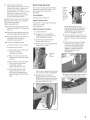
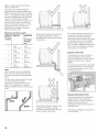
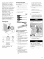
Dryer Dimensions
Dimension Weight
a 27,0" (68,6cm) 125 Ibs
b 31,8" (81,0cm) (56,7kg)
c (min)* 36,9" (93,6cm) with
packaging
c 37,8" (95,9cm) 143 Ibs
(max)* (64,8kg)
d 22,0" (59,7cm)
angle160°
e 53,9" (136,9cm)
* min=dryer feet all the way in, max=out
Useful Tools
The following tools are helpful during
installation:
1. T20 star head screwdriver
2. Philips screwdriver (#2)
3. Flat blade screwdriver
4. Open end wrench 1 in. (25mm)
5. Bubble level
1
3
Checklist for Installation
1. Unpack the dryer.
2. Remove all objects from the drum.
3. Check the dryer for visible
damage.
4. Position the dryer near the
installation location (see page 8).
5. If required, change the door hinge
to the left (see page 9).
6. If required, install the side or
bottom exhaust air outlet on the
dryer (see page 19).
7. Have the power supply cord fitted
by a qualified technician or a
licensed electrician (see page 14).
,
Check for "Y" connection, short
hose and water supply hose
included with the dryer packaging
(see page 13). (Selected models
only).
,
Connect the water supply
(selected models only) to the back
of the dryer (see page 13 for
detailed instructions).
10. Install exhaust ductwork if
necessary.
%
Follow the installation instructions
supplied by the appropriate
ductwork parts manufacturers (see
page 18)
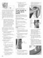
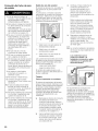
If space is very restricted, it is
recommended to fit the initial parts
of the exhaust duct to the dryer
before the dryer is moved to its
final installation location.
DO NOT push against the dryer
door glass. Risk of breakage!
Do not
push against
the do6r glass!
11. Move the dryer to its final location.
Do not slide dryer across the
floor if height-adjustable feet
have been extended. Feet and/or
dryer base may be damaged if
dryer is slid across floor with
height-adjustable feet extended.
12. Position and then level the dryer.
-i!iiiiii!i_!ii_!_i!i_>_ ¸ ii!_!__ii_ii_
J
LJ
/
The dryer should be level with all four
feet firmly on the ground. The dryer
must not wobble. If the dryer is not level
or if it does wobble, the feet must be
adjusted. Adjust the height-adjustable
feet using the 1 in. (25mm) wrench until
the dryer does not rock and is level,
both front-to-back and side-to-side.

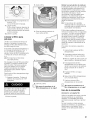
Aftermakingpreliminary
adjustments,pressdownoneach
cornerofthedryertomakesure
theunitdoesnotwobble.If
pressingdownonacornercauses
thedryertowobble,lowerthe
dryerfootonthatcorneruntilthe
foottouchesthefloorfirmly.
Installthedryerandlevelitfromsideto
sideandfronttoback.Useabubble
level.Neverremovethe
height-adjustablefeet!
13.Connecttheexhaustducttothe
exhaustairoutletonthedryer(see
page17).
14.Insertthedryerelectricalpluginto
thewallreceptacle(seepage14).
15.Readtheoperatinginstructionsto
understandhowyourdryer
operates.(seepage20).
16.Conductanappliancetest:
Checkthatthedrumisempty.
Closethedryerdoor.
Switchthedryerto"ExtraDry"
andthenpressthe
"Start/Pause"button.
After3 5minutespressthe
"Start/Pause"buttonandopen
thedoor.
Iftheinteriorofthedryerfeels
warm,thedryerhasbeen
connectedproperly.
Switchthedryerto"OFF".
Ifthedryerdoesnotwork,
switchthedryerto"OFF".
Lookinthetroubleshooting
section(page30)andfindthe
fault.
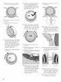
Door Hinge Reversal
The door is hinged on the right hand
side of the dryer at the factory. The
door hinge can be reversed if
necessary.
Tools Needed
T20 star head screwdriver
Hinge Reversal Parts
Hinge (with 4 white plastic bushings)
Hinge Cover Plate
Door Assembly
Hinge Reversal Procedure
1. Unplug the dryer.
2. Prepare a firm, flat, padded
surface to lay the dryer door on
while changing the hinge.
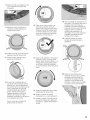
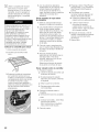
3. Open the dryer door to fully
expose the hinge cover.
4. Remove the 4 screws holding the
hinge cover in place.
remove
four
screws
Set the cover aside along with the
four screws for later reinstallation.
5. Rotate the door so that it is
perpendicular to the dryer front.
Slide the door away from the dryer
so the hinge pins slide out of the
grooves in the dryer door.
check to
make
sure that
all four
plastic
bushings
remain on
the hinge
pins
Avoid allowing the 4 plastic
bushings to fall off the hinge pins.
If any of the bushings do fall off,
reinstall them on the hinge pins
prior to reinstalling the door.
6. Lay the dryer door face down on a
firm, flat, padded surface, with the
bottom of the door facing towards
you.
7. Remove the two screws holding
the striker cover plate in place.
Hold the striker while lifting the
cover so as to keep the parts
together in place and set the
assembly aside for later
reinstallation.
8. Remove the single screw that was
hidden by the striker plate cover.
9

9. Remove the four screws holding
the front ring to the door body.
10. Flip the door over so the front ring
faces up.
11. Remove the front ring from the
dryer door.
12. The cover glass has a raised glass
edge that goes about two thirds
of the way around the glass. Be
sure this raised edge faces up
towards you. Observe the position
of the leading edge of the raised
glass handle, marked in the
illustration below as (A).
Rotate the cover glass 90 degrees
clockwise.
13. Note the new position of the cover
glass. The leading edge of the
raised glass edge should have
moved 90 degrees clockwise from
its starting point as shown in the
illustration below as (A).
14. Rotate the front ring 180 degrees
so the door handle is now on the
right hand side. The door handle
is located on the inside of the front
ring. It is a hand-sized indent.
15. Flip the door over so the back
faces up.
16. Reassemble the parts, preserving
their new alignments.
17. Reinsert the single screw that goes
under the striker plate. Tighten the
screw securely.
18. Rotate the striker cover and striker
180 degrees so the assembly fits
to the install area on the opposite
side of the door (where the hinge
had been). Reinstall the striker
cover and striker to the new
location and securely tighten the
two cover screws.
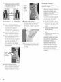
19. Reinsert and tighten the four front
ring screws.
20. Remove the two screws holding
the plastic cover plate over the left
hand hinge mounting position on
the dryer housing. Remove the
plate and set itaside with the two
screws.
21. Remove the two screws holding
the metal door hinge to the dryer
housing. Remove the hinge from
the housing.
Right Hand to Left Hand
22. Reattach the door hinge to the
dryer housing at the left side of the
dryer door opening. Tighten both
screws completely, making sure
they hold the hinge securely.
23. The door is now ready to be
mounted back on the dryer.
10

24. Reinstall the dryer door by sliding it
onto the hinge pins.
Avoid allowing the four plastic
bushings to fall off the hinge pins.
If any fall off, reinstall them on the
hinge pins prior to reinstalling the
dryer door.
reinstall
the
dryer
door
25. Reinstall the hinge cover plate
removed in step 4. Insert and
tighten the 4 screws holding the
hinge cover plate in place.
reinstall
four
screws
and
tighten
securely
26. Install the plastic cover plate over
the original hinge position at the
right hand side of the dryer door
opening. Insert and tighten the
two screws holding the plate in
place.
27. Test that the door opens and
closes properly. The door should
latch securely. The hinge reversal
process is complete.
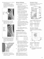
Minimum Distances
Important information concerning
minimum distances:
Depending on the location of the
exhaust air connection, an
additional minimum distance of
51/2inch (14 cm) must be provided
on this side, the side the
connection is on, for
ducts/brackets (see page 19).
Benefits of maintaining greater
distance (clearances) than the
minimum shown include:
• more air cools the dryer, keeps
the dryer from overheating, and
improves drying performance.
• reduction of the risk of mold
formation behind the appliance.
• reduced noise transmission
• facilitation of installation and
service.
If the dryer is installed in a small
room, the doors of the room must
be fitted with vents of the specified
minimum size. Refer to the
following illustrations of enclosed
installations for additional
information.
Allow additional clearance for
door, wall and window molding
where necessary.
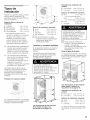
Installation Types
Observe the following minimum
clearances between the dryer and
adjacent surfaces for all installation
types.
Minimum Installation Clearances
A Sides 0.25in.(6.4mm)
B Top 0.25in.(6.4mm)
C Rear* 5.25in.(13.4cm)
D Front 0,50in,(12,8mm)
* asclosetowallasventingor water
connectionwillallow If installedwith a
washer,thelargerrearclearancefor dryer
ventingis requiredfor thelaundrypair
Units are designed so that the
dryer can be stacked on top of the
washer using one of the stacking
kits shown on page 19.
Units are designed to allow for
under-counter installation See
required dimensions in under
counter installation section on
page 12.
Height measurements shown in this
section are with the dryer feet at
minimum extension (turned in all the
way up against the base of the dryer).
Recessed or Closet
Dimensions for installation in a closet or
recessed area are shown in the
illustration below.
Closet Ventilation Requirements
E Top 48sq.in.(310sq.cm)
F Bottom 24sq,in,(155sq,cm)
Required Installation Space
G Height 37.25in.(94.6cm)
H Width 27.50in,(69.9cm)
I Depth 37.25in. (94.6cm)
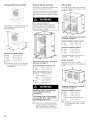
Mounted on Pedestal
Dimensions for pedestal mounting
installation are shown in the illustration
below.
Required Installation Space
G Height 52.25in.(132.7cm)
H Width 27.50in.(69.9cm)
I Depth 37.25in,(94,6cm)
J PedestalHt, 15,0in.(38.1cm)
D Appliance must not be mounted
on a pedestal for under counter
installations.
11

Pedestal With Pull-Out Shelf
iii
Dimensions for pedestal and pull-out
shelf installation are shown in the
illustration below.
Required Installation Space
G Height 53.75in.(136.5cm)
H Width 27.50in,(69.9cm)
I Depth 37.25in.(94.6cm)
J Pedestalht 15,0in.(38.1cm)
D Appliance must not be mounted
on a pedestal for under counter
installations.
J
Stacked Washer and Dryer
Dimensions for stacked installation are
shown in the illustration below.
There are two stacking kits available for
stacking the dryer on top of the washer.
See the "Accessories" section on page
19.
More than two people are
recommended to lift the dryer into
position because of its weight and
size. Failure to do so could result in
persona njury or death.
Clearance dimensions A through D
are found on page 11.
Closet Ventilation Requirements
E Top 48sq,in.(310sq,cm)
F Bottom 24sq,in,(155sq,cm)
Required Installation Space
G Height* 74.50in,(189,3cm)
*with basicstackingkit
Height** 76.02in, (t93,1 cm)
**with pull-out shelfstackingkit
H Width 27.50in,(69.9cm)
I Depth 37.25in. (94.6cm)
Appliance must not be mounted
on a pedestal for stacked
installations.
The washer must not be stacked
on top of the dryer. Serious injury
and damage may result.
D Utilize care in sliding the stacked
washer and dryer units into place.
See the stacking kit installation
instructions for further information.
Side by Side
Dimensions for side by side recessed
or closet installation are shown in the
illustration below.
H
Clearance dimensions A through D
are found on page 11.
Closet Ventilation Requirements
E Top 48sq,in.(310sq,cm)
F Bottom 24sq,in,(155sq,cm)
Required Installation Space
G Height 37.25in,(94.6cm)
H Width 54.75in,(t39,t cm)
I Depth 37.25in. (94.6cm)
Height Requirement if mounted on a
pedestal 52.25in.(132.7cm)
Under-Counter
Dimensions for under counter
installation are shown in the illustration
below.
B
Clearance dimensions A through D
are found on page 11.
Required Installation Space
G Height 37.25in.(94.6cm)
H Width 27.50in,(69.9cm)
Width* 54.75in,(139,tcm)
* washer and dryer side by side
I Depth 37.25in.(94.6cm)
D Appliance must not be mounted
on a pedestal for under counter
installations.
12

Water Connection
This section applies only to dryers
with a water connection. The
connection is found at the top
back of 500 and 800 Series
Dryers with the Steam logo on the
panel.
%;;
Steam
Steam Dryer Parts Supplied
The following parts are included with
the shipment of your dryer:
2
0 3
4
supplied parts illustration. It is
illustrated separately from the hose
for clarity.
3. If space permits, attach the
internally threaded (female) end of
the "Y" connector directly to the
cold water faucet (option A as
shown in the illustration above)
and continue to step 6
For optional Installation with Y
Connector
If the "Y" connector cannot be
attached directly, use the short
hose provided to connect the "Y"
connector to the cold water faucet
(option B as shown in the
illustration below), and continue
with steps 4 through 5.
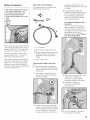
Attach the dryer water supply hose to a
cold water faucet (the faucet must be
located within 4 ft (1.2 m) of the water
inlet valve on the back of the dryer).
It is recommended to have a water
supply pressure of 20 100 psi (1.37
6.89 bar) for best performance.
Since most connections will share the
cold water faucet used by the clothes
washer, a "Y" connector is provided
along with a short hose (ifneeded) in
order to connect the water supply hose
to the cold water faucet.
1. "Y" connector
2. Short metal-braided inlet hose
3. Rubber washer (inserted in female
end of short inlet hose, shown
separately here for purposes of
clarity).
4. water supply hose
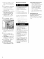
Connecting the Water Inlet Hose
D The dryer must be connected to
the "Y" connector using the water
supply hose provided. Do not use
an old hose.
1. Turn off the cold water tap and
remove the washer water supply
hose from the tap.
4. Attach the short hose to the cold
water faucet. Tighten the
connection by hand until the
coupling is seated on the faucet.
5. Use pliers to tighten the
connection an additional
two thirds turn.
2. Check to be sure that the rubber
washer is fully inserted and seated
in the female end of the short hose
prior to continuing. The rubber
washer is shown as item 3 in the
D Do not overtighten. Damage to
the coupling could result.
13

6. Attach the "Y" adapter to the short
hose. Tighten the coupling (by
hand) until it is firmly seated on the
hose.
D Do not use pliers to tighten plastic
threaded fittings onto plastic or
metal threaded connections.
7. Attach the washer cold water
supply hose to the "Y" connector.
Hand tighten only.
8. Attach the dryer water supply hose
to the other coupling of the "Y"
connector. Hand tighten only.
9. Tighten only metal-to metal
couplings on the "Y" connector
and short hose an additional
two thirds turn using pliers.
D Do not overtighten. Damage to
the coupling could result.
Electrical Connection
Power cord must be connected
by a qualified technician or a
licensed electrician only.
Connect to individual branch
circuit.
Do not use an adapter.
Do not use an extension cord.
Do not remove ground prong.
Your dryer comes without a power
supply cord. The power cord must
meet the following requirements:
UL listed in the USA
208 - 240 volt rated (minimum)
30 amps
Type SRDT or DRT (UL 2158)
Five feet long (minimum)
Power cord must be connected
Additional grounding procedure
Some local regulations may
require a separate ground. In such
cases, the required accessory
ground wire, clamp and screw
must be purchased separately.
Contact your local dealer or
customer service for additional
details (see page 32).
Never ground the dryer to plastic
plumbing lines, gas lines or water
pipes.
Grounding instruction
This appliance must be grounded. In
the event of a malfunction or
breakdown, grounding will reduce the
risk of electric shock by providing a
path of least resistance for the electric
current.
10. Attach the right angle connector
on the water supply hose to the
inlet valve located at the top left of
the dryer.
D Check to see that the rubber
washer does not fall out, and is
properly seated in the right angle
connector.
11. Hand tighten the coupling until it
is seated on the connector. Do
not use pliers, hand tighten only.
D Do not overtighten. Damage to
the coupling could result.
12. Turn on the water faucet.
13. Check for leaks around the "Y"
connector, faucet and all hoses.
by a qualified technician or a
licensed electrician only.
Use only a U.L. approved
30 amp power cord with strain
relief clamp -
note manufacturer's instructions.
Do not reuse old power cord.
Cord must have closed loop or
upturned end wire terminating
connectors.
Do not make a sharp bend or
crimp wiring/conductor at
connections.
Only a 4-conductor cord shall
be used when the appliance is
installed in a mobile home, in a
recreational vehicle, in a new
branch circuit installation or an
area where the local codes do
not permit grounding through
the neutral.
14

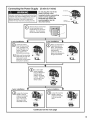
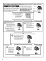
Connecting the Power Supply
Improper connection of the equipment grounding
conductor may result in electric shock. Have the
appliance checked by a qualified technician or
licensed electrician if you are in doubt as to
whether the dryer has been properly grounded,
(3 wire & 4 wire)
Do not plug the end of the
power cord into a live
receptacle before connecting
power cord to appliance
terminals and closing the
junction/splitter box as
described below.
terminal bmock
grounding strap
bracket for _1__
strain relief clamp
4 wire
®
Q emove the two screws fromthe terminal block cover
located at the top rear of the
appliance. This will expose
the terminal block assembly.
__!_!ii_i_i_]i_i_i_i_i_ii_!i!:_!_!i_!i_!i_!_!i!i_i_ii!_!i!_i!i_!_i!i_iiiiiii_iii!_!iii_iii_ii_ii_ii_i_!i!_i!_!_!i_i!!_iiiiii!!!i_ii!!iH_iiii!_iiiiii_iii!iiiiiiiii!ii]ii!!_iilo ._
installation
_r 3 wire installation
Loosen the bottom
screw of the grounding
strap. Straighten the
grounding strap so it is
vertical. Replace the
green screw in the
GROUND terminal hole.
Make sure the grounding
strap does not touch the
back panel to avoid
tripping the circuit breaker
during dryer operation,
Q ake sure that there is
a grounding strap in
place. The illustration
shows the grounding
strap properly
positioned, with the
green screw fastened to 0
the ground terminal.
Fix a strain relief
clamp (available
from an electrical or
building supply
outlet) to the angle
bracket. Tighten the
nut to firmly fix the •
clamp in place,
4 wire installation
3 wire installation
Q Loosen the 2
screws
labeled L and the
single screw labeled
N on the terminal
block. Also loosen
the screw on the
GROUND terminal.
Q oosen the 2 screws
labeled L and the
single screw labeled
N on the terminal
block.
Continued on the next page
15

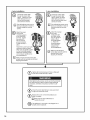
4 wire installation 3 wire installation
Q Thread the 4-wire cable
through the strain relief
clamp. Tighten the strain
relief clamp screws (2.5
Nm) so that the power
cord cannot be moved.
I_] his will hold the power cord in
place and will make it easier to
correctly install the terminal
screws.
®
D
Attach the power
cord ground
conductor (green)
to the GROUND
terminal. Tighten
the screw (2.5
Nm) so that the
ground conductor
is held securely in
place.
Attach the 2 power cord outer
conductors (red and black,
either one can go left or right)
on the 2 terminals labeled L.
Attach the remaining power
cord conductor (white) to the
terminal labeled N.
Make sure the terminal screws align
properly with the terminal nuts to avoid
stripping the threads.
®
®
D
Thread the 3-wire cable
through the strain relief
clamp. Tighten the strain
relief clamp screws (2.5
Nm) so that the power cord f_3 _'_,
cannot be moved. _Ji!__ _
This will hold the power cord in
place and will make it easier to
correctly install the terminal
screws,
Attach the 2 power
cord outer
conductors (red
and black, either
one can go left or
right) on the 2
terminals labeled
L. Attach the
remaining power
cord conductor
(white) to the
terminal labeled N.
Make sure the terminal
screws align properly with the
terminal nuts to avoid
stripping the threads,
m
Q ighten all 3 terminal screws (3 Nm) so that each
of the wires is held securely in place.
After tightening the screws, test to see that the terminals
are held securely in place to assure proper electrical
connection, otherwise a hazardous condition could
result.
Q heck the strain relief clamp to make sure that it
is tight and cannot be turned.
Q eplace the cover on the terminal block and
fasten it in place.
Make sure the strain relief clamp is
outside the cover!
Q he appliance is now ready to be plugged into a
properly rated receptacle,
16

Exhaust air connection
The following warnings must be
adhered to without exception.
1. To reduce the risk of fire, this dryer
MUST BE EXHAUSTED
OUTDOORS.
2. To reduce the risk of fire, do not
use ductwork longer than
recommended. Refer to the
maximum ductwork length table
(see page 18).
3. DO NOT use a plastic, metal foil,
or any other non-metal duct with
this dryer. Only rigid or flexible
metal duct shall be used for
exhausting. Metal foil and flexible
metal ducting are NOT the same.
4. DO NOT use more than 2.4 m of
flexible metal ducting.
5. DO NOT use a duct smaller than 4
inches (101.6mm) in diameter.
6. DO NOT exhaust the dryer into: a
chimney, wall, ceiling, concealed
space of a building, furnace cold
air duct, attic, crawl space, or any
other ductwork used for venting.
7. DO NOT install a flexible duct in an
enclosed wall, ceiling or floor.
8. DO NOT crush or kink the duct.
9. Do clean and inspect the exhaust
system on a regular basis; at least
once a year.
10. The exhaust duct must terminate
with an approved exhaust vent
hood to prevent back drafts or
entry of birds or other wildlife.
11. DO NOT use exhaust hoods with
magnetic latches.
12. DO NOT assemble the duct work
with screws or fasteners that
extend into the duct. They serve
as an accumulation point for lint.
Joints should be secured with
aluminum tape.
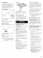
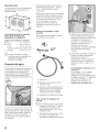
Exhaust air outlet on the dryer
The dryer is delivered with an exhaust
air outlet on the rear of the appliance.
Alternative exhaust duct connection
options are illustrated below. Select
one of these options to make best use
of the space available or an existing
exhaust ductwork system.
1 - Exhaustairoutletontherearofthe
appliance(standard)
2 - Exhaustair outletontheside(optional)
3 - Exhaustair outletonthe undersideof
the appliance(optional)
Special exhaust air connections can be
obtained from your dealer, part supplier
or customer service for either
connection type (see page 19).
Side exhaust kit
Bottom exhaust kit
A qualified technician should change
the exhaust air outlet to the optional
connection location.
Ductwork
The dryer vent system moves moist air
away as your clothes tumble dry. You
can shorten drying times, save energy
and help ensure the safety of the
system by making sure your dryer's
exhaust duct system is properly
installed and maintained.
Important Points to Consider:
Keep exhaust duct runs (total
length of the exhaust duct system
from the dryer to the exhaust hood
outside) as short as possible (refer
to the table "Maximum Ductwork
Length" on page 18.)
Use the minimum number of
elbows needed when installing the
exhaust duct system. Avoid
placing two 90 degree elbows
adjacent to one another.
Check and clean the exhaust duct
system and exhaust hood at least
once each year, and any time you
suspect dryer performance is
decreased.
%
Remove accumulated lint to
prevent diminished air flow or
clogging of the system.
Professional cleaning is
recommended annually and when
attaching your dryer to a previously
used exhaust duct system.
Replace any plastic or metal foil
venting sections with rigid metal or
flexible metal ducting. Rigid metal
ducting is recommended.
Correct exhaust system installation
isthe responsibility of the
consumer.
D Problems that result from
incorrect installation are not
covered by the appliance
warranty.
Exhaust ducting which is longer than
specified in the maximum ductwork
length table on page 18 is not
permitted. Not adhering to this table
will extend drying time, cause lint to
accumulate and affect dryer
performance and life-time.
All joints should be tight to avoid leaks.
The male end of each duct section
must point away from the dryer.
Whether connecting to an existing
venting system or a new venting
17

system, make sure that all ducting is
clean and free of lint.
The maximum permitted length for
rigid duct and for rigid duct used with
flexible metal duct is shown in the table
below. If using flexible metal ducting to
connect the appliance to the ductwork
system, the total length of flexible
metal duct used shall not exceed 2.4 m
and can only be used to connect the
dryer to the ductwork system. As the
table below shows, the maximum
overall ductwork length is reduced if
flexible ducting is used.
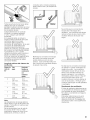
Maximum Ductwork Length
Numberof
90°Turns
or Elbows
RigidDuct
FlexibleDuct
in
Combination
with Rigid
Duct
0 66 ft. 45 ft.
(2011 cm) (1372 cm)
1 56ft. 36 ft.
(1707cm) (1097cm)
2 48 ft. 29ft.
(1463cm) (884cm)
3 39ft. 22 ft.
(1189cm) (671cm)
4 30ft. 16ft.
(914cm) (488cm)
Note:
Side and bottom exhaust installations
have a 90°turn inside the dryer. Take
this into account when using the table
above.
The use of more than two 90° turns are
not recommended. For best
performance, separate all turns by at
least 4 ft. of straight duct, including
distance between last turn and exhaust
hood.
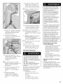
Good
Better
Keep exhaust ductwork as short and
as straight as practical. This will
increase air flow and result in shorter
drying times.
_ii/iiidiiii
i \
Do not allow exhaust ductwork to be
longer than necessary. Longer
ductwork will reduce airflow and will
result in longer drying times.
Do not allow exhaust ductwork to be
crushed or otherwise constricted.
Constricted ductwork will reduce
airflow and result in longer drying times.
Constricted ductwork could reduce
exhaust airflow enough to cause an
error condition, halting the dryer cycle.
Check to be sure the exhaust duct is
not crushed or constricted.
Exhaustventhood
The exhaust duct must end with an
approved exhaust vent hood with
swing out damper(s). DO NOT use an
exhaust vent hood with magnetic
latches.
To avoid exhaust restriction, the outlet
must be a minimum of 12 inches (30
cm) above ground level or any other
obstructing surface.
Required Ductwork Parts
The parts required for the exhaust air
system (elbows, lines, exhaust air
outlets) are not included in standard
delivery of the dryer (seethe
Accessories section for information on
ordering parts.)
Professional installation of ductwork is
recommended.
18

Accessories
The following optional accessories for
your dryer may be obtained from
customer service (see page 32) or from
your local dealer. Please follow the
installation instructions supplied by the
appropriate manufacturer.
Side exhaust kit
i
o
part no. WTZ 1265
Note:
See notes on maximum number of
elbows on page 18.
Bottom exhaust kit
part no. WTZ 1270
Note:
See notes on maximum number of
elbows on page 18.
D The bottom exhaust kit cannot be
used with a pedestal installed on
the dryer or ifthe dryer is stacked
with the washer.
Dryer rack
part no. WTZ1620
Use the dryer rack to dry washable
woolen textiles (e.g. sweaters) and
shoes.
Pedestal Mounting Kit
A storage pedestal with a pull-out
drawer is available as an accessory for
your dryer. The pedestal adds
approximately 15 inches to the height
of the dryer. See page 11 for
dimensions.
Appliance must not be mounted
on a pedestal in stacked
installations.
part no. WTZ 1610 isfor a solid white
color pedestal.
Other color pedestals may be
available.
Reference part no. WTZ 1610"X" in
which the X designates an available
color (eg: A for Anthracite, S for silver).
Please inquire at your dealer for color
choices available.
You may also consult a current product
catalog or visit our website at:
www.boschappliances.com
If mounting the dryer on a pedestal,
follow the instructions supplied with the
pedestal.
Stacking Kits
There are two stacking kits available.
Basic Stacking Kit
This kit anchors the dryer on top of the
washer and adds approximately 0.63
inches (16 mm) to the stacked height.
See page 12 for dimensions.
part no. WTZ 1601 is for the basic
mechanical stacking kit.
Pull-Out Shelf Stacking Kit
This kit serves to stack the dryer on top
of the washer and also provides a pull-
out shelf. This kit adds approximately
1.52 inches (38.6 mm) to the stacked
washer/dryer height. See page 12 for
dimensions.
This kit may also be combined with the
pedestal mounting kit to provide a
pull-out shelf as well as a combined
increase in height of the dryer of
approximately 16.5 inches.
D The pedestal can not be combined
with the pull-out shelf stacking kit
in stacked washer/dryer
installations.
part no. WTZ 1600 isfor the solid
white pull-out shelf stacking kit.
Other color pull-out shelf stacking
kits may be available.
Reference part no. WTZ 1600"X" in
which the X designates an available
color (eg: A for Anthracite, S for silver).
Please inquire at your dealer for color
choices available.
Preparing to transport the
dryer - step by step
D These procedures should only be
performed by a qualified person.
1. Rotate the program selector
to "OFF".
2. Disconnect the power supply (turn
the circuit breaker off, unplug the
appliance)
3. Turn off the water faucet
connected to the water supply
hose (Steam models only).
Disconnect the water supply hose.
4. Disconnect the exhaust duct from
the exhaust air outlet on the dryer.
5. Collect any accessories and
package them for shipment with
the appliance.
6. Close the door and secure with
adhesive tape.
7. Screw the height-adjustable feet of
the dryer into the housing to
prevent them from being damaged
during transportation.
.
Reinstallation of the Dryer at the
New Location refer to the
Installation Instructions in this
manual (see page 7).
19

OPERATING INSTRUCTIONS
Before using
To reduce the risk of fire, electric
shock, or injury to persons, read the
IMPORTANT SAFETY
INSTRUCTIONS before operating
this appliance.
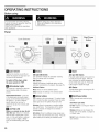
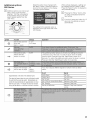
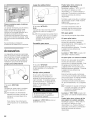
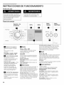
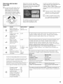
Panel
Pe_m Pie58
Cycle Se_ectc-
n
Time D_
Before using your dryer, read and
follow all installation and operating
instructions.
Cotton
LED's
D
Display
n
Option
Buttons
O
Delicates £L©
O0
Start/Pau se
Button
bl
Cycle Selector
Switchesthemachineonandoff and
selectstheprogram(seepage22).Can
beturnedin bothdirections.
To switch off the dryer, rotate
the cycle selector to "Off".
LEDIndicator
Lights
LED'Slightupin sequencetoshowthe
currentmoisturestateofthe drying
process.
Wrinkle Block/Finished- attheend
ofthedryingcycleanacousticsignal
soundsandtheWrinkleBlock/Finished
LEDlightsup, Thedrumrotatesat
specificintervalsfor onehourto
preventthelaundryfrom creasing(see
page23 ),
_1 Lint Filter LED
Blinks as a reminderto cleanthe lint
filter after use. Blinksfor 10seconds
whenthedoorisopenedaftera cycle
ends,or inthe eventairflowis reduced
enoughtocreatea "CLn"or "E:12"
error(seetroubleshootingguide,page
30),
Display
300 and 500 Series
LEDcountdownindicatesthe estimatedremaining
timeof a runningcycle(in minutes).
800 Series
Indicatesthe settingsofadditionaloptionsandthe
estimatedremainingtimeof programs.(Seepage25)
AdditionalOptions
Menuselectsoneoftheadditionaloptions
Select changesthesettingsoftheselectedoption
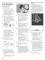
Option buttons
Addfunctionsto thecycleselected.Theoptionbutton
LEDis litwhentheoptionisselected.Presstheoption
buttonagaintoturntheoptionoff(LEDturnsoff).
Delicates:Pressfortemperaturesensitivetextiles
(e.g.acrylicfibers).Thetemperatureof thedrying
processisreduced,thedryingtime isextended
correspondingly.
ECOAction: Pressfor additionalenergysavings(use
onlyforcottonandpermanentpresscycles),Pressthe
optionbuttonpriorto startingan automaticcycle,
r_ Signal
300 and 500 Series
Pressbothoptionbuttonsatthesametime
to enabletheacousticsignal, Whenthe
cycleisfinished,an audiblebeepingtone
willbe emitted(seepage22), Pressboth
buttonsagainto disablethesignal,
800 Series
The800 Seriessignalisset usingtheLCD
menu(seepage25).
Start/Pause Button
Starts,interruptsandendsthedrying
process,
Start/PauseLEOStatus
Lit Red:Programis runningand"Pause"
canbeactivated,
Blinking: Settingscanbechanged,the
dryingcyclecanbestarted,or programis
in "Pause"mode.
Not Lit: Cycleisfinishedor thereis no
cycleselected.
2O
Page is loading ...
Page is loading ...
Page is loading ...
Page is loading ...
Page is loading ...
Page is loading ...
Page is loading ...
Page is loading ...
Page is loading ...
Page is loading ...
Page is loading ...
Page is loading ...
Page is loading ...
Page is loading ...
Page is loading ...
Page is loading ...
Page is loading ...
Page is loading ...
Page is loading ...
Page is loading ...
Page is loading ...
Page is loading ...
Page is loading ...
Page is loading ...
Page is loading ...
Page is loading ...
Page is loading ...
Page is loading ...
Page is loading ...
Page is loading ...
Page is loading ...
Page is loading ...
Page is loading ...
Page is loading ...
Page is loading ...
Page is loading ...
Page is loading ...
Page is loading ...
Page is loading ...
Page is loading ...
Page is loading ...
Page is loading ...
Page is loading ...
Page is loading ...
Page is loading ...
Page is loading ...
Page is loading ...
Page is loading ...
-
 1
1
-
 2
2
-
 3
3
-
 4
4
-
 5
5
-
 6
6
-
 7
7
-
 8
8
-
 9
9
-
 10
10
-
 11
11
-
 12
12
-
 13
13
-
 14
14
-
 15
15
-
 16
16
-
 17
17
-
 18
18
-
 19
19
-
 20
20
-
 21
21
-
 22
22
-
 23
23
-
 24
24
-
 25
25
-
 26
26
-
 27
27
-
 28
28
-
 29
29
-
 30
30
-
 31
31
-
 32
32
-
 33
33
-
 34
34
-
 35
35
-
 36
36
-
 37
37
-
 38
38
-
 39
39
-
 40
40
-
 41
41
-
 42
42
-
 43
43
-
 44
44
-
 45
45
-
 46
46
-
 47
47
-
 48
48
-
 49
49
-
 50
50
-
 51
51
-
 52
52
-
 53
53
-
 54
54
-
 55
55
-
 56
56
-
 57
57
-
 58
58
-
 59
59
-
 60
60
-
 61
61
-
 62
62
-
 63
63
-
 64
64
-
 65
65
-
 66
66
-
 67
67
-
 68
68


Bosch WTVC3300US/09 Owner's manual
- Category
- Electric laundry dryers
- Type
- Owner's manual
- This manual is also suitable for
Ask a question and I''ll find the answer in the document
Finding information in a document is now easier with AI
in other languages
Related papers
-
Bosch WTMC8521UC/05 Owner's manual
-
-
-
Bosch WTV76100US/06 Owner's manual
-
-
-
-
-
-
Other documents
-
Pittsburgh Corning 100843 Installation guide
-
LG TD-V70120E Owner's manual
-
LG DLGY1902KE User guide
-
LG DLEX7600WE Owner's manual
-
 Kenmore Elite 71553 Owner's manual
-
 Kenmore Elite 61552 Owner's manual
-
LG DLGY1902KE Owner's manual
-
LG DLE7200VE Owner's manual
-
LG DLG7301VE Owner's manual
-
 Kenmore Elite 61433 Owner's manual


