Page is loading ...

Switch Mode
DC Power
Supplies
SEC-1212P
SEC-1223P
SEC-1235P
SEC-1235P-M
Please read this
manual BEFORE
installing your
Power Supply.
Owner's
Manual

2 | SAMLEX AMERICA INC.
SECTION 1
Safety Instructions .................................................................3
SECTION 2
Layout & Dimensions ............................................................5
SECTION 3
Description & Operation .......................................................8
SECTION 4
Troubleshooting Guide ........................................................12
SECTION 5
Limiting Electro-Magnetic Interference (EMI) .......................13
SECTION 6
Specications ......................................................................16
SECTION 7
Warranty ..........................................................................22
OWNER'S MANUAL | Index
Disclaimer of Liability
UNLESS SPECIFICALLY AGREED TO IN WRITING, SAMLEX AMERICA INC:
1. MAKES NO WARRANTY AS TO THE ACCURACY, SUFFICIENCY OR SUITABILITY OF ANY TECHNICAL OR OTHER INFORMATION
PROVIDED IN ITS MANUALS OR OTHER DOCUMENTATION.
2. ASSUMES NO RESPONSIBILITY OR LIABILITY FOR LOSSES, DAMAGES, COSTS OR EXPENSES, WHETHER SPECIAL, DIRECT,
INDIRECT, CONSEQUENTIAL OR INCIDENTAL, WHICH MIGHT ARISE OUT OF THE USE OF SUCH INFORMATION. THE USE OF
ANY SUCH INFORMATION WILL BE ENTIRELY AT THE USERS RISK.
Samlex America Inc reserves the right to revise this document and to periodically make changes to the content
hereof without obligation or organization of such revisions or changes.
Copyright Notice/Notice of Copyright
Copyright © 2016 by Samlex America Inc. All rights reserved. Permission to copy, distribute and /or modify this
document is prohibited without express written permission by Samlex America Inc.

SAMLEX AMERICA INC. | 3
SECTION 1 | Important Safety Instructions
1.1
!
CAUTION!
RISK OF ELECTRIC SHOCK! DO NOT OPEN!
WARNING—TO REDUCE THE RISK OF FIRE OR ELECTRIC SHOCK, DO NOT
EXPOSE THIS APPLIANCE TO RAIN OR MOISTURE. THERE ARE NO USER
SERVICEABLE PARTS INSIDE — REFER TO QUALIFIED SERVICE PERSONNEL.
!
ATTENTION!
RISQUE DE CHOC ÉLECTRIQUE ! N’OUVREZ PAS !
AVERTISSEMENT - POUR RÉDUIRE LE RISQUE D’INCENDIE OU DE CHOC
ÉLECTRIQUE, NE PAS EXPOSER CET APPAREIL À LA PLUIE OU L’HUMIDITÉ,
IL N’Y A PAS DE PIÈCE À L’INTÉRIEUR - REPORTEZ-VOUS À UN PERSONNEL
QUALIFIÉ
1.2 SYMBOLS
The following safety symbols will be used in this manual to highlight safety
and information:
WARNING!
Indicates possibility of physical harm to the user in case of non-compliance.
MISE EN GARDE!
L’utilisateur pourrait se blesser lorsque les consignes de sécurité ne sont pas
suivies.
!
CAUTION!
Indicates possibility of damage to the equipment in case of non-compliance.
!
ATTENTION!
Il y a un risque d’endommager l’équipement lorsque l’utilisateur ne suit pasles
instructions.
i
INFO
Indicates useful supplemental information.

4 | SAMLEX AMERICA INC.
1.3 GENERAL
Please read before using your power supply:
a) It Is recommended that you return your power supply to a qualied Samlex dealer for
any service or repair. Incorrect assembly may result in electric shock or re.
b) To reduce the risk of electric shock, unplug the power supply from the outlet before
attempting any maintenance or cleaning. Turning off controls will not reduce this risk.
c) An extension cord should not be used unless absolutely necessary. If an extension cord
must be used, make sure that the pins on the plug are the same number, size and
shape as those of the country specic power cord plug. Also, the voltage and current
specs of the extension cord should match the voltages and current capacities of the
power supply.
d) Place the unit in an area that will allow air to ow freely around the unit. DO NOT
BLOCK OR OBSTRUCT vent openings on the sides of the unit.
e) Keep the unit away from moisture and water.
f) NEVER operate the units in parallel.
1.4 GROUNDING
WARNING!
Your power supply should be grounded to reduce the risk of electric shock. The
power supply is equipped with grounding provision in the IEC 320-C14 Power
Cord Inlet.
Country specic power cord must be plugged into an outlet that is properly
installed and grounded in accordance with all local codes and ordinances.
Improper connection can result in risk of electric shock.
MISE EN GARDE!
Votre alimentation doit être mis à la terre pour réduire le risque de choc électrique.
L’alimentation est équipé d’un disposition de la mise à la terre IEC 320-C14 Cordon
d’Inlet.
Le cordon doit être branché dans une prise de courant correctement installée
et mise à la terre conformément à tous les codes et règlements locaux. Une
connexion incorrecte peut entraîner un risque de choc électrique.
1.5 CONNECTION TO A BATTERY
DO NOT USE THE POWER SUPPLY FOR DIRECT CHARGING OF BATTERY OR DIRECT
CONNECTION TO A BATTERY FOR BATTERY BACK-UP. (Please read Section 3.5).
SECTION 1 | Important Safety Instructions

SAMLEX AMERICA INC. | 5
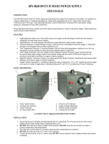
SECTION 2 | Layout & Dimensions
2.1 SEC-1212P
2
4
3
4
3
1
7
5 5
Overall Dimension: 185 x 208 x 57.8 mm
(with protrusions) 7.28 x 8.19 x 2.28 in
6
Bottom View
190
57.8
180
180
185
2.5 2.5
208
4.5
53.3
Figure 2.1 Layout & Dimensions - SEC-1212P
LEGEND for Fig 2.2
1. Lighted Power ON/OFF Rocker Switch (Lights Red when ON)
2. AC Power Cord Inlet: Type “IEC 60320-C14” for detachable power cord with
“IEC 60320-C13” connector on one end and country specic plug on the other end.
3. Black Negative (-) DC Load Terminal
Tubular hole Dia 5mm/0.2” and set screw (5/64” Hex Socket Head, #10, 24 TPI,
5/16” long)
*See Note 2
4. Red Positive (+) DC Load Terminal
Tubular hole Dia 5mm/0.2” and set screw (5/64” Hex Socket Head, #10, 24 TPI,
5/16” long)
*See Note 2
5. Air cooling slots in the top cover for cooling by convection
6. Air cooling slots at the bottom housing for cooling by convection
7. Lanced tab that slides into corresponding slot in the bottom housing. (There is one more
lanced tab on the other corresponding side of the top cover).
NOTES: 1. The top cover will t properly only when the 2 lanced tabs (7, Fig 2.1) are oriented
towards the DC output terminals 3 and 4 .
2(a). 5/64” Hex Key and 2 spare set screws have been provided.
2(b). 2 pieces of Pin Type Terminals (for wire size up to AWG#8) have also been provided
for crimping to bare stranded wire ends of load wiring for rm contact under the
set screws.

6 | SAMLEX AMERICA INC.
SECTION 2 | Layout & Dimensions
2.2 SEC-1223P AND SEC-1235P
4
3
4
3
1
7
5
Overall Dimension: 185 x 208 x 57.8 mm
(with protrusions) 7.28 x 8.19 x 2.28 in
[W x D x H]
6
Bottom View
190
57.8
180
180
185
2.5 2.5
208
4.5
53.3
2
8
Figure 2.2 Layout & Dimensions - SEC-1223P & SEC-1235P
LEGEND for Fig 2.2
1. Lighted Power ON/OFF Rocker Switch (Lights Red when ON)
2. AC Power Cord Inlet: Type “IEC 60320-C14” for detachable power cord with
“IEC 60320-C13” connector on one end and country specic plug on the other end.
3. Black Negative (-) DC Load Terminal
Tubular hole Dia 5mm/0.2” and set screw (5/64” Hex Socket Head, #10, 24 TPI,
5/16” long)
*See Note 2
4. Red Positive (+) DC Load Terminal
Tubular hole Dia 5mm/0.2” and set screw (5/64” Hex Socket Head, #10, 24 TPI,
5/16” long)
*See Note 2
5. Air inlet slots on the top cover for cooling fan suction
6. Air inlet slots in the bottom for cooling fan suction
7. Lanced tab that slides into corresponding slot in the bottom housing. (There is one more
lanced tab on the other corresponding side of the top cover). This ensures that the top cover
ts properly only in one orientation i.e. with ventilation slots 5 positioned away from the fan
discharge openings 8 .
8. Ventilation openings for fan discharge (outwards). Fan is located behind the ventilation openings.
NOTES: 1. The top cover will t properly only when the 2 lanced tabs (7, Fig 2.2) are oriented
towards the DC output terminals 3 and 4 .
2(a). 5/64” Hex Key and 2 spare set screws have been provided.
2(b). 2 pieces of Pin Type Terminals (for wire size up to AWG#8) have also been provided for
crimping to bare stranded wire ends of load wiring for rm contact under the set screws.

SAMLEX AMERICA INC. | 7
SECTION 2 | Layout & Dimensions
2.3 SEC-1235P-M
4
3
4
3
7
5
Overall Dimension: 185 x 208.5 x 57.8 mm
(with protrusions) 7.28 x 8.21 x 2.28 in
[W x D x H]
6
Bottom View
190
57.8 4.5
180
180
185
2.5
2.5
208.5
4.5
53.3
57.8
2
8
1
5
10
10
9
11
LEGEND for Fig 2.3
1. Lighted Power ON/OFF Rocker Switch (Lights Red when ON)
2. AC Power Cord Inlet: Type “IEC 60320-C14” for detachable power cord with “IEC 60320-C13”
connector on one end and country specic plug on the other end.
3. Black Negative (-) DC Load Terminal
Tubular hole Dia 5mm/0.2” and set screw (5/64” Hex Socket Head, #10, 24 TPI,
5/16” long)
*See Note 2
4. Red Positive (+) DC Load Terminal
Tubular hole Dia 5mm/0.2” and set screw (5/64” Hex Socket Head, #10, 24 TPI,
5/16” long)
*See Note 2
5. Air inlet slots on the top cover for cooling fan suction
6. Air inlet slots in the bottom housing for cooling fan suction
7. Lanced tab that slides into corresponding slot in the bottom housing. (There is one more lanced tab
on the other corresponding side of the top cover). This ensures that the top cover ts properly only in
one orientation i.e. ventilation slots 5 positioned away from the fan discharge openings 8 .
8. Ventilation openings for fan discharge (outwards). Fan is located behind the ventilation openings.
9. Lighted Volt and Ammeter:
Voltmeter: 0 to 15V ; 0.5V per division
Ammeter: 0 to 50A ; 2A per division
10. Screw adjustment for mechanical zeroising of Voltmeter and Ammeter needles.
11. On/Off Push Button for meter back light.
NOTES: 1. The top cover will t properly only when the 2 lanced tabs (7, Fig 2.3) are oriented
towards the DC output terminals 3 and 4 .
2(a). 5/64” Hex Key and 2 spare set screws have been provided.
2(b). 2 pieces of Pin Type Terminals (for wire size up to AWG#8) have also been provided for
crimping to bare stranded wire ends of load wiring for rm contact under the set screws.
Figure 2.3 Layout & Dimensions - SEC-1235P-M

8 | SAMLEX AMERICA INC.
SECTION 3 | Description & Operation
3.1. DESCRIPTION
SEC-1212P / SEC-1223P / SEC-1235P / SEC-1223P-M are Switched Mode Power Supplies (SMPS)
which convert 100-240 VAC, 50/60 Hz to regulated 13.8 VDC.
Features
• Complies with Minimum Energy Performance Standard (MEPS) for External Power
Supplies and meets Directives issued by: CEC (USA)/ DoE (USA) / NRCan (Canada)/ GEMS
- MEPS (Australia and New Zealand) / ErP Directive (European Union) / International
Efciency Marking Protocol
• Efciency Levels: (i) Level VI at input voltage of 115VAC (ii) Level VI at input voltage
of 230 VAC
• Universal AC input range of nominal 100 VAC to 240 VAC, 50 to 60 Hz allows interna-
tional application without changing jumpers / switch positions
• Power Factor (PF) corrected to > 0.9 at loads > 50% allows lower input current and line
losses, lesser harmonic distortion and lower RF noise
• Uses highly integrated Switched Mode Controller combining PWM Control & Active
Power Factor Correction for lower component count, higher efciency and reliability
3.2. CONNECTION & OPERATION
WARNING!
Before plugging the unit to the AC outlet, please check that your local supply
voltage is 100-240 VAC, 50/60 Hz.
NOTE! The DC output connectors (3 and 4, Figs 2.1 to 2.3) have a tubular hole
of diameter 0.2” (5mm) with a set screw. For a rm connection, crimp/solder
pin type copper terminal on the cable ends of your 12V DC device (2 Pin Type
of terminals (for wire size up to AWG #8) have been supplied with the unit].
MISE EN GARDE!
Avant de brancher l’unité à la prise secteur, veuillez vérier que votre tension
d’alimentation est de 100-240 VCA, 50/60 Hz.
REMARQUE ! Les connecteurs de sortie (DC 3 et 4, gures 2.1 à 2.3) a un di-
amètre de trou tubulaire 0,2” (5mm) avec une vis. Pour un lien ferme, à sertir/
soudez les broches de cuivre de type borne sur les extrémités du câble de votre
appareil DC 12V (2 broches type de terminaux ont été fournis avec l’appareil).
Ensure that the power supply’s ON/OFF switch (1, Fig 2.1 to 2.3) is off and the power supply
is unplugged from the AC outlet. Switch off your 12 V DC device and connect it’s Positive
and Negative to the RED (Positive) and BLACK (Negative) terminals respectively (3 and 4, Figs
2.1 to 2.3). Ensure that the connections are secure and tight. Plug the power supply into the

SAMLEX AMERICA INC. | 9
SECTION 3 | Description & Operation
AC outlet. Press the ON/OFF switch of the power supply to ON and observe that the neon
indicator in the switch illuminates. If the indicator fails to light , recheck the connection,
AC outlet and the fuse inside the power supply.
SEC-1235P-M has Voltmeter and Ammeter (9, Fig 2.3). If necessary, use adjusting screws (10, Fig
2.3) to zeroise the needles (do this with the unit in OFF condition). If required, the back light of
the meter can be switched ON using ON/OFF Push Button for the back light (11, Fig 2.3).
Your 12V DC device may now be switched ON.
3.3 COOLING AND OVER TEMPERATURE PROTECTION
3.3.1 Cooling and Over Temperature Protection: SEC-1212P
INSTAL IN WELL VENTILATED, OPEN, COOL AND DRY AREA. DO NOT BLOCK VENTILATION
OPENINGS ON THE SIDES AND IN THE BOTTOM
SEC-1212P is cooled by convection. For this, it has ventilation slots on the 2 sides of the top
cover (5, Fig 2.1) and in the bottom housing (6, Fig 2.1).
Over temperature protection is provided by Temperature Sensor mounted on the Primary
Heat Sink. The output power of the unit will be shut down if the if the Primary Heat Sink
temperature rises to 105˚C ± 5˚C or above due to one or more of the following reasons:
• Ambient temperature ratings given in the specications at Section 6 have been exceeded
• Ventilation slots on the sides of the top cover (5, Fig 2.1) and in the bottom housing (6,
Fig 2.1) are blocked
The output power will be reset automatically when the Primary Heat Sink cools down to
75˚C ± 5˚C or lower.
3.3.2 Cooling and Over Temperature Protection: SEC-1223P/1235P/1235P-M
INSTAL IN WELL VENTILATED, OPEN, COOL AND DRY AREA. DO NOT BLOCK SUCTION AND
DISCHARGE VENTILATION OPENINGS ON THE SIDES AND IN THE BOTTOM
SEC-1223P/1235P/ SEC-1235P-M are cooled by convection and by forced air cooling by
temperature controlled fan. The fan sucks cool air from the inlet slots located towards the
front sides of the top cover (5, Fig 2.2 and 2.3) and the front side of the bottom housing
(6, Figs 2.2 and 2.3). The air is discharged from the rear ventilation openings in the bottom
housing behind the fan (8, Figs 2.2 and 2.3).
The fan operation is controlled by Temperature Sensor mounted on the Secondary Heat
Sink inside the unit. The fan will turn ON only if the Secondary Heat Sink temperature
rises to 55˚C ± 5˚C or higher due to (i) higher loads (ii) higher ambient temperature, or
(iii) poor cool air change around the unit. Thus, the fan may remain OFF when supplying
lower loads in cooler ambient temperature. The fan will switch OFF automatically when
the Secondary Heat Sink temperature cools down to 45˚C ± 5˚C.

10 | SAMLEX AMERICA INC.
In case (i) the fan fails or, (ii) the suction / discharge ventilation openings are blocked or,
(iii) the ambient temperature ratings given in the specications at Section 6 have been
exceeded, temperature inside the unit will continue to rise. A second Temperature Sensor
mounted on the Primary Heat Sink will shut down the output power if the Primary Heat
Sink temperature rises to 105˚C ± 5˚C or above. The output power will be reset automati-
cally when the Primary Heat Sink cools down to 75˚C ± 5˚C or lower.
3.3.3 Orientation of Top Cover Fitment – SEC-1223P/1235P/1235P-M
In SEC-1223P/1235P/1235P-M, the fan sucks cool air from the inlet slots located towards the
front sides of the top cover (5, Fig 2.2 and 2.3) and the front side of the bottom housing
(6, Figs 2.2 and 2.3). The air is discharged from the rear ventilation openings in the bottom
housing behind the fan (8, Figs 2.2 and 2.3). For proper air ow path from the front to the
rear, it is necessary that the top cover is tted with the side ventilation slots (5, Fig 2.2 and
2.3) oriented towards the front. To ensure this, 2 lanced tabs (7, Fig 2.2 and 2.3) are provided
in the top cover that will slide into the corresponding slots in the rear side of the bottom
housing. The top cover will not t properly if the ventilation slots are facing towards the rear
side because the lances tabs will interfere with the top edge of the front side of the bottom
housing (there are no corresponding slots on the front side of the bottom housing)
3.3.4 Orientation of Top Cover Fitment – SEC-1212P
In SEC-1212P, there is no fan. Cooling is carried out by convection through the ventilation
slots on the 2 sides of the top cover (5, Fig 2.1) and in the bottom housing (6, Fig 2.1). For
improved cooling of the Primary Heat Sink through conduction, the air gap between the top
surface of the Primary Heat Sink and the bottom surface of the top cover is lled by using
a thermally conductive gap ller strip of soft, ceramic lled silicone elastomeric material.
When the top cover is removed and tted back, its orientation has to be such that the ther-
mally conductive gap ller strip gets positioned properly on top of the Primary Heat Sink.
To ensure this, 2 lanced tabs (7, Fig 2.1) are provided in the top cover that will slide into the
corresponding slots in the rear side of the bottom housing. The top cover will not t prop-
erly if the 2 lanced tabs (7, Fig 2.1) are facing towards the front side of the bottom housing
because the lances tabs will interfere with the top edge of the front side of the bottom
housing (there are no corresponding slots on the front side of the bottom housing).
3.4 OVERLOAD / SHORT CIRCUIT PROTECTION
3.4.1 Unit is used as a Power Supply without Battery Backup (12V Battery is
not Connected to the Battery Terminals)
Refer to Fig 3.1 under Section 3
The SMPS Section is provided with Hiccup Mode of Overload and Short Circuit protections.
Output load current from the SMPS is fed through a series connected, 0.1875 Ohm Load
Sense Resistor inside the SMPS. Output load current produces voltage drop across the Load
Sense Resistor. This voltage drop is proportional to the value of the load current. Protections
are triggered based on the voltage drop sensed across the Load Sense Resistor as follows:
SECTION 3 | Description & Operation

SAMLEX AMERICA INC. | 11
a) Hiccup Mode Overload Protection: When the voltage drop across the Load Sense
Resistor in the SMPS Section is more than 5.18 to 5.44V (output current > 27.6 to
29A) and is sustained for 40-50ms, Hiccup Mode Overload Protection is triggered.
The output of the SMPS is shut down. After 3 to 4 sec, the SMPS Section is switched
ON again. If the overload still exists for 40-50ms, the SMPS will shut down again.
Hence, for a continuous overload of > 27.6 to 29A, the SMPS Section switches ON
and OFF (hiccup) every 3 to 4 sec. The average output voltage of the SMPS during
this protection will be nearly 0V.
b) Hiccup Mode Short-Circuit Protection: When the voltage drop across the Load Sense
Resistor inside the SMPS Section is more than 7.5V (output current > 40A) and is
sustained for 4 to 6.5 ms, Hiccup Mode Short Circuit Protection is triggered. The
output of the SMPS is shut down. After 2 to 3 sec, the SMPS is switched ON again. If
the short circuit still exists for 4 to 6.5 ms, the SMPS will shut down again. Hence, for
a continuous short circuit, the SMPS switches ON and OFF (hiccup) every 2 to 3 sec.
The average output voltage of the SMPS during this protection will be nearly 0V.
3.5 BATTERY CHARGING & BATTERY BACK-UP
WARNING!
These units are power supplies and not battery chargers. Do not connect these
units directly to a battery.
MISE EN GARDE!
Ces unités sont des unités d’alimentation et non pas les chargeurs de batterie.
Ne pas connecter ces appareils directement à une batterie.
These units should NOT BE DIRECTLY CONNECTED TO A BATTERY for charging or for
battery back-up. Battery charging and battery back-up may be undertaken only when the
battery is connected through suitable external isolating diodes and charge limiting resistor.
The isolating diode will ensure that the battery does not back power the power supply. When
a battery is deeply discharged, it will initially draw a very large charging current and thus, will
force the power supply into current limit mode for prolonged periods. This is harmful for the
power supply. The charge limiting resistor will limit the charging current, thereby, ensuring
that the maximum charging current is well below the current limit value of the power supply.
i
INFO
It is recommended that the following optional battery back-up modules may
be used for battery back-up application:
For SEC-1212P and SEC-1223P: Battery Back Up Module Model No. BBM-1225
For SEC-1235P / 1235P-M: Battery Back Up Module No. BBM-12100
SECTION 3 | Description & Operation

12 | SAMLEX AMERICA INC.
4.1 TROUBLESHOOTING GUIDE IS GIVEN AT TABLE 4.1 BELOW
NOTE: This guide is based on operation as a power supply (only DC load is connected - no
external battery or battery backup).
TABLE 4.1 TROUBLESHOOTING GUIDE
Symptom Possible Cause Remedy
ON / OFF Switch is ON
• Switch is NOT lighted
• No DC output
No AC power from the
AC outlet
Check AC power is available at the AC outlet.
Breaker feeding the AC outlet may have tripped.
Internal AC side fuse is
blown
(i) Open the top cover and check the AC side
fuse. Replace if blown.
(ii) If the fuse blows again, the input section is
damaged. Please call Tech Support.
Unit has shut down due
to over temperature –
Temperature of Primary
Heat Sink is ≥ 105°C ± 5°C
For SEC-1223P / 1235P / 1235P-M:
(i) Check that the fan is running. If not, the
fan / fan control circuit may have been
damaged. Call Tech Support.
(ii) Check that fan air suction rents on the sides
(5, Figs 2.2 and 2.3) and bottom (6, Fig 2.2
and 2.3) and fan air discharge vents (8, Figs
2.2 and 2.3) are not blocked.
(iii) The unit will reset automatically when the
Primary Heat Sink cools down to 75°C ±
5°C or below.
For SEC-1223P / 1235P / 1235P-M:
(i) Check the ventilation slots on the top cover
(5, Fig 2.1) and in the bottom housing
(6, Fig 2.1) are not blocked.
(ii) Check ambient temperature is withing
specications in Section 6.
(iii) The unit will reset automatically when the
Primary Heat Sink cools down to 75°C ±
5°C or below.
ON / OFF Switch is ON
• Switch is lighted
• DC Output voltage is in
Hiccup Mode:
On à Off for 2 to 3 sec à
On à Off for 2 to 3 sec
à Off (This sequence is
repeated continuously).
Refer to Section 3.4 for details.
• The output side is
overloaded as the value
of the load current is
higher than the value of
the output current limit
(Refer to output current
limit specications at
Section 6).
• There’s a short circuit on
the load side.
• Reduce the current drawn by the load to
less than the DC output current limit value
(Refer to output current limit specications in
Section 6).
• Switch OFF the load. Remove the short circuit
on the load side.
GFCI outlet / GFCI breaker
supplying AC power to the
unit trips when the unit is
switched ON
RF noise currents from
the unit that are ltered
to Earth Ground have
increased the net Leakage
Current on the GFCI outlet
/ GFCI breaker to > 5mA
(i) Switch OFF other SMPS devices operating
from the same GFCI outlet / GFCI breaker to
reduce the net leakage current to < 5mA
(ii) Move the unit to another GFCI outlet / GFCI
breaker that has lesser number of SMPS
load(s) or no SMPS load
(ii) Power the unit from normal, non GFCI outlet or
from an outlet not protected by GFCI breaker
SECTION 4 | Troubleshooting Guide

SAMLEX AMERICA INC. | 13
SECTION 5 | Limiting Electro-Magnetic
Interference (EMI)
5.1
!
CAUTION!
Conducted and radiated noises in this unit are limited as per the applicable
National / International Standards. Refer to the applicable standards given in
the specications in Section 6.
This unit generates, uses and can radiate radio frequency energy and, if not
installed and used in accordance with the instructions, may cause harmful
interference to radio communications. However, this does not guarantee that
interference will not occur in a particular installation. If this equipment does
cause harmful interference to radio or television reception, which can be
determined by turning the equipment off and on, the user is encouraged to
try to correct the interference by one or more of the measures recommended
in the following paragraphs.
!
ATTENTION!
Bruits et rayonnement dans cette unité sont limitées que par la législation
nationale / normes internationales. Consulter les normes mentionnées dans les
spécications de la Section 6.
Cet appareil génère, utilise et peut émettre une énergie de fréquence radio et,
s’il n’est pas installé et utilisé conformément aux instructions, peut causer des
interférences nuisibles aux communications radio. Cependant, cela ne garantit
pas qu’aucune interférence ne se produira dans une installation particulière.
Si cet équipement provoque des interférences nuisibles à la réception radio ou
télévision, ce qui peut être déterminé en éteignant l’équipement, l’utilisateur
est encouragé à essayer de corriger les interférences en prenant une ou plusieurs
des mesures recommandées dans les paragraphes suivants.
5.2 UN-INTENTIONAL RF NOISE GENERATED BY SWITCHED
MODE POWER SUPPLIES (SMPS)
Switched Mode Power Supplies (SMPS) employ high frequency switching (25-170 KHz in
these units) and thus, are a source of radio interference, a recipient of radio interference
and a conduit of radio interference. (Older Linear Type, low frequency 50 / 60 Hz trans-
former based power supplies do not employ high frequency switching voltages and will be
quieter as compared to SMPS).
The primary emission sources originate in the switching devices due to their fast switching
current transitions: harmonics of the switching frequency and broadband noise created by
under-damped oscillations in the switching circuit. The secondary source is from the bridge
rectier, both rectier noise and diode recovery. The noise is both conducted and radiated
through the input power cord and the DC output wiring to the radio.

14 | SAMLEX AMERICA INC.
SECTION 5 | Limiting Electro-Magnetic
Interference (EMI)
5.3 FILTRATION OF CONDUCTED NOISE
The conducted RF noise from these SMPS units is limited to the maximum allowable levels by
internal ltration. The ltered RF noise currents (< few hundred micro Amps) are bypassed
to the chassis of the power supply. The chassis is, in turn, connected to the Earth Ground pin
of the AC input power cord. Thus, the ltered noise currents are intentionally leaked to the
Earth Ground. This is termed as the “Earth Leakage Current”.
5.4 EXCESSIVE RF OUTPUT INTERFERENCE BY SMPS DUE TO
INCOMING RF INTERFERENCE WHEN POWERING RADIO TX / RX
SMPS are also recipients of radio interference. The normal operation of the power supply
can be disturbed due to RF noise getting coupled into the power supply. Thus, the power
supply may generate excessive RF noise and lose output voltage regulation due to excessive
transmitter energy being coupled through the AC / DC lines to the power supply’s regulator
feedback path. This may be due to antenna being too close or due to the antenna or feed
system not radiating properly. First check the antenna system SWR. Then, if necessary,
relocate either the antenna or the power supply farther apart. The receiver may “hear” the
power supply. A slowly moving, slightly buzzing carrier heard in the receiver may be caused
by the antenna being too close. As with the transmitter related noise pick up, a loose coaxial
connector or a broken or a missing ground may aggravate this problem. Normally, this noise
will be below the background or “band” noise. Increase the separation between the power
supply and the receiving antenna. Use an outdoor antenna. This will reduce the amount of
signal picked up from the power supply and also increase the amount of the desired signal.
5.5 ADDITIONAL GUIDELINES FOR REDUCING RF NOISE
• Use additional appropriate AC Radio Frequency Interference (RFI) Power Line Filter
immediately before the AC input of the power supply (should be rated for the AC
input voltage and input current of the power supply). Filtered, Ferrite Coated Cord
Set for AC input is another choice (rated for AC input voltage and input current of the
power supply). These cord sets, with integral line interference lters, reduce Common
and Differential Mode Interferences over a wide frequency range. Because they are
shielded, they are also effective against radiated interferences. In addition to the
built-in lter networks, the cable conductors are coated with an RF absorbing ferrite
compound. This provides additional attenuation at high frequencies that is lacking in
most regular LC lters. The RF absorption of the ferrite-coated cable avoids resonances
at high frequencies, reducing the conducted and radiated RF noises even further.
• Use additional appropriate DC radio frequency interference (RFI) power line lter
immediately after the DC output of the power supply.
• Twist the Positive and Negative wires from the output of the power supply to the radio.

SAMLEX AMERICA INC. | 15
• The DC side Positive and Negative outputs of these power supplies are isolated from
the chassis. As explained earlier, the noise currents are ltered to the chassis of the unit
and the chassis is connected to the Earth Ground through the Earth Ground Pin of the
AC power outlet receptacle. Avoid connecting (referencing) the DC Negative output
terminal of the power supply to the Earth Ground.
• Connect a ¼” wavelength of wire on the Negative terminal of the power supply.
Connect one end of the wire to the Negative terminal and leave the other end free.
The wavelength corresponds to the wavelength of the interfering frequency. (May not
be practical for long wave lengths).
[Formula: Wave length (Meters) = 300 / frequency in MHz]
5.6 COMBINED FILTERED NOISE CURRENTS FROM MULTIPLE SMPS
ON A BRANCH CIRCUIT MAY TRIP GROUND FAULT CIRUIT IN-
TERRUPTER (GFCI)
During malfunction or an accident, the metal chassis of an electrical device may get energized
to unsafe voltage due to internal high voltage section coming in contact with the chassis. If a
person standing on Earth touches this energized chassis, a leakage current proportional
to the person’s skin resistance will ow through the person’s body to Earth Ground. The
leakage current through the body is higher when the skin contact resistance is lower i.e. if
the skin is wet or wounded. This leakage current does not return to the power source but
is dissipated in Earth Ground. A leakage current of > 4-6mA passing through the human
body could produce lethal electrical shock. Ground Fault Circuit Interrupter (GFCI) is used
for safety against electrical shock due to leakage. GFCI measures the difference between
the current sent to the load and returned from the load and will trip and disconnect
the power circuit if the difference is > 4-6 mA. GFCIs are normally installed in AC Branch
Circuits feeding power outlets in wet areas like marine craft, RVs, spas, hot-tubs, kitchens,
washrooms, etc.
As explained earlier at Section 5.2, RF noise ltration circuits in SMPS generate intentional
Earth Leakage Current. SMPS are used extensively as DC power sources in modern day
electrical / electronic devices e.g. Audio / Video / Computing devices, power supplies, battery
chargers etc. A single GFCI outlet / GFCI breaker may be serving multiple SMPS loads and
therefore, will be sensing the sum of all the Earth Leakage Currents and, if the sum is
> 4-6mA after connecting this unit, the GFCI will trip. In such a case, disconnect other SMPS
based device(s) being served by this GFCI one by one till the net leakage current is reduced
to < 4mA and the GFCI does not trip. Other solution is to power this unit from a GFCI outlet
/ GFCI breaker that does not have any SMPS load or power from an outlet that is not
protected by GFCI.
SECTION 5 | Limiting Electro-Magnetic
Interference (EMI)

16 | SAMLEX AMERICA INC.
SECTION 6 | Specications
NOTE: Specications are subject to change without notice.
6.1 SEC-1212P
Input: 115 VAC Input: 230V
INPUT
Input Voltage Range 100-240 VAC
Input Frequency Range 50-60Hz (47-63Hz)
AC Input Current
1.48A at 120 VAC 0.72A at 240 VAC
1.54A at 115 VAC 0.75A at 230 VAC
1.80A at 100 VAC 0.90A at 200 VAC
Inrush current on switching ON 30A (Cold start) 60A (Cold start)
Power Factor at full load > 0.9
No Load Power Draw < 0.21W <0.5W
Average Efciency > 89% >91%
Energy Efciency Level
Level VI at 115 VAC input
Level VI at 230 VAC input
PWM Switching Frequency 75 to 150 KHz
PFC Switching Frequency 25 to 68 KHz
OUTPUT
Output Voltage 13.8V ± 0.1V
Output
Current
Rated 11A
Current Limit 13.2 to 14.2A 13.7A
Output Power 151.8W
Output Ripple and Noise 100 mV peak to peak at full load
Output Voltage Adjustment Range 12.5 to 15.0 VDC
Output Voltage Tolerance at no load ± 0.1V
PROTECTIONS
Overload and Short Circuit Hiccup Mode at 120% (13.2A). Auto reset when fault is removed.
Output Over Voltage Protection By PWM Controller (16.5 ± 0.5 VDC)
Cooling By convection. No fan
Over Temperature Protection
The unit will shut down when the temperature of the
Primary Heat Sink rises to 105°C ± 5°C. Auto reset
when the temperature drops to 75°C ± 5°C
Internal AC Side Fuse 250V, 2.5A; Time Delay Type; 5mm x 20mm
ENVIRONMENTAL
Operating Temperature -20°C to +50°C: 100% rated power
Over Temperature Protection
50°C – 60°C: Linearly de-rate from 100% power
at 50°C to 80% power at 60°C
COMPLIANCE - SAFETY
UL Safety Listed
USA UL 62368-1, 2014-12-1
Canada CSA C22.2 No. 62368-1-14, 2014-12

SAMLEX AMERICA INC. | 17
SECTION 6 | Specications
Input: 115 VAC Input: 230V
COMPLIANCE - SAFETY (Continued)
European CE Safety Marked
• Low Voltage Directive (LVD) 2014/35/EU
• EN62368-1 : 2014+A11 : 2017
Australia and New Zealand Safety
Requirements
AS/NZS 60950-1: 2015
COMPLIANCE: EMC
North America EMI: FCC Part 15(B), Class B
Europe (for CE Mark)
EMC Directive: 2014/30/EU
EMI: EN55032:2012;
• EN61000-3-2: 2014
• EN61000-3-3: 2013
EMS: EN55024: 2010
• EN61000-4-2: 2009;
• EN61000-4-3:2006+A1:2008+A2:2010
• EN61000-4-4:2012
• EN61000-4-5:2014
• EN61000-4-6:2014
• EN61000-4-8:2010
• EN61000-4-11:2004
Australia / New Zealand EMI: AS/NZS CISPR 32, Class B
COMPLIANCE: RoHS2
For European CE Mark 2011/65/EU (RoHS2)
COMPLIANCE: ENERGY EFFICIENCY OF EXTERNAL POWER SUPPLIES
USA Department of Energy (DOE) 10CFR, Parts 429 and 430
California Appliance Efciency
Regulations
California Code of Regulations, Title 20, Division 2,
Chapter 4, Article 4, Sections 1601 to 1608
Natural Resources Canada (NRcan) CSA C381.1- 08
Australia and New Zealand AS/NZS 4665.1
European Union
Directive 2005/32/EC and European Commission
Regulation (EC) No. 278/2009
International Efciency Marking
Protocol
Efciency Level: VI at input voltage of 115 VAC
Efciency Level: VI at input voltage of 230 VAC
DIMENSIONS
W x D x H 185 x 208 x 57.8mm / 7.28 x 8.19 x 2.28 in
Weight 1.4 Kg / 3 lb
COUNTRY OF MANUFACTURE
Made in Taiwan
NOTE: Specications are subject to change without notice.

18 | SAMLEX AMERICA INC.
SECTION 6 | Specications
NOTE: Specications are subject to change without notice.
6.2 SEC-1223P
Input: 115 VAC Input: 230V
INPUT
Input Voltage Range 100-240VAC
Input Frequency Range 50-60Hz (47-63Hz)
AC Input Current
3.01A at 120 VAC 1.49A at 240 VAC
3.15A at 115 VAC 1.55A at 230 VAC
3.7A at 100VAC 1.85A at 200 VAC
Inrush current on switching ON 30A (Cold start) 60A (Cold start)
Power Factor at full load 0.99 0.97
No Load Power Draw < 0.5W < 0.5W
Average Efciency > 89% > 91%
Energy Efciency Level
Level VI at 115 VAC input
Level VI at 230 VAC input
PWM Switching Frequency 75 to 150 KHz
PFC Switching Frequency 25 to 68 KHz.
OUTPUT
Output Voltage 13.8V ± 0.1V
Output
Current
Rated 23A
Current Limit 27.6 to 29.0A 27.5A
Output Power 317.4W
Output Ripple and Noise 100 mV peak to peak at full load
Output Voltage Adjustment Range 12.5 to 15.0 VDC
Output Voltage Tolerance at no load ±0.1V
PROTECTIONS
Overload and Short Circuit Hiccup Mode at 120% (27.6A). Auto reset when fault is removed.
Output Over Voltage Protection By PWM Controller (16.5 ± 0.5 VDC)
Cooling
Fan ON when the temperature of Secondary Heat Sink reaches 55°C
± 5°C. Fan switches OFF when the temperature drops to 45°C ± 5°C
Over Temperature Protection
The unit will shut down when the temperature of the Primary Heat Sink rises
to 105°C ± 5°C. Auto reset when the temperature drops to 75°C ± 5°C
Internal AC Side Fuse 250V, 4.0A; Time Delay Type; 5mm x 20mm
ENVIRONMENTAL
Operating Temperature -20°C to +50°C: 100% rated power
Over Temperature Protection
50°C – 60°C: Linearly de-rate from 100% power at 50°C to 80%
power at 60°C
COMPLIANCE - SAFETY
UL Safety Listed
USA UL 62368-1, 2014-12-1
Canada CSA C22.2 No. 62368-1-14, 2014-12

SAMLEX AMERICA INC. | 19
SECTION 6 | Specications
Input: 115 VAC Input: 230V
COMPLIANCE - SAFETY (Continued)
European CE Safety Marked
• Low Voltage Directive (LVD) 2014/35/EU
• EN62368-1 : 2014+A11 : 2017
Australia and New Zealand Safety
Requirements
AS/NZS 60950-1: 2015
COMPLIANCE: EMC
North America EMI: FCC Part 15(B), Class B
Europe (for CE Mark)
EMC Directive: 2014/30/EU
EMI: EN55032:2012;
• EN61000-3-2: 2014
• EN61000-3-3: 2013
EMS: EN55024: 2010
• EN61000-4-2: 2009;
• EN61000-4-3:2006+A1:2008+A2:2010
• EN61000-4-4:2012
• EN61000-4-5:2014
• EN61000-4-6:2014
• EN61000-4-8:2010
• EN61000-4-11:2004
Australia / New Zealand EMI: AS/NZS CISPR 32, Class B
COMPLIANCE: RoHS2
For European CE Mark 2011/65/EU (RoHS2)
COMPLIANCE: ENERGY EFFICIENCY OF EXTERNAL POWER SUPPLIES
USA Department of Energy (DOE) 10CFR, Parts 429 and 430
California Appliance Efciency
Regulations
California Code of Regulations, Title 20, Division 2,
Chapter 4, Article 4, Sections 1601 to 1608
International Efciency Marking
Protocol
Efciency Level: VI at input voltage of 115 VAC
Efciency Level: VI at input voltage of 230 VAC
DIMENSIONS
W x D x H 185 x 208 x 57.8mm / 7.28 x 8.19 x 2.28 in
Weight 1.53 Kg / 3.4 lb
COUNTRY OF MANUFACTURE
Made in Taiwan
NOTE: Specications are subject to change without notice.

20 | SAMLEX AMERICA INC.
NOTE: Specications are subject to change without notice.
6.3 SEC-1235P AND 1235P-M
Input: 115 VAC Input: 230V
INPUT
Input Voltage Range 100-240 VAC
Input Frequency Range 50-60Hz (47-63Hz.)
AC Input Current
3.87A at 120 VAC 1.91A at 240 VAC
4.05A at 115 VAC 1.99A at 230
4.80A at 100 VAC 2.4A at 200 VAC
Inrush current on switching ON 30A (Cold start) 60A (Cold start)
Power Factor at full load 0.99 0.97
No Load Power Draw < 0.5W < 0.5W
Average Efciency > 89% > 92%
Energy Efciency Level
Level VI at 115 VAC input
Level VI at 230 VAC input
PWM Switching Frequency 75 to 150 KHz
PFC Switching Frequency 25 to 68 KHz
OUTPUT
Output Voltage 13.8V ± 0.1V
Output
Current
Rated 30A
Current Limit 36 to 37.5A 36.3A
Output Power 414W
Output Ripple and Noise 100 mV peak to peak at full load
Output Voltage Adjustment Range 12.5 to 15.0 VDC
Output Voltage Tolerance at no load ± 0.1V
Output Metering
(Only for SEC-1235P-M)
SEC-1235P-M is provided with the following meters:
• Voltmeter : 0 to 15V; 0.5V per division
• Ammeter: 0 to 50A; 2A per division
• Back lighting with On/Off Switch
PROTECTIONS
Overload and Short Circuit Hiccup Mode at 120% (36A). Auto reset when fault is removed.
Output Over Voltage Protection By PWM Controller (16.5 ± 0.5 VDC)
Cooling
Fan ON when the temperature of Secondary Heat Sink reaches 55°C
± 5°C. Fan switches OFF when the temperature drops to 45°C ± 5°C
Over Temperature Protection
The unit will shut down when the temperature of the Primary Heat Sink rises
to 105°C ± 5°C. Auto reset when the temperature drops to 75°C ± 5°C
Internal AC Side Fuse 250V, 6.3A; Time Delay Type; 5mm x 20mm
ENVIRONMENTAL
Operating Temperature
-20°C to +50°C: 100% rated power
50°C – 60°C: Linearly de-rate from 100% power
at 50°C to 80% power at 60°C
SECTION 6 | Specications
/