
vacon nx
ac drives
brake resistors
user manual
®


Technical data vacon • 1
24-hour support: +358 (0)201 212 575 • Email: vacon@vacon.com
INDEX
Document code: DPD01573B
Date edited: 24.4.2015
1. GENERAL ...................................................................................................................................... 2
1.1
Requirement for braking .................................................................................................... 2
1.2
Brake components ............................................................................................................. 2
1.3
Classes of use .................................................................................................................... 2
2. TECHNICAL DATA ......................................................................................................................... 3
2.1
Standard resistors for partial use ...................................................................................... 3
2.1.1 380…500V range ........................................................................................................................ 4
2.1.2 208…240V range ........................................................................................................................ 5
2.1.3 525…690V range ........................................................................................................................ 6
2.2
Other resistors ................................................................................................................... 8
2.3
Power rating of standard resistors .................................................................................... 9
2.4
Environment ..................................................................................................................... 11
2.5
Thermal protection for the LD resistors .......................................................................... 12
2.5.1 Thermal protection: ................................................................................................................ 13
3. CHOICE OF BRAKE RESISTOR .................................................................................................... 14
3.1
General ............................................................................................................................ 14
3.2
Sizing principles ............................................................................................................... 14
3.2.1 Calculating braking time ......................................................................................................... 15
3.2.2 Calculating the moment of inertia .......................................................................................... 15
3.2.3 Internal resistors .................................................................................................................... 19
4. CONNECTIONS ............................................................................................................................ 20
4.1
General ............................................................................................................................ 20

2 • vacon technical data
Tel. +358 (0)201 2121 • Fax: +358 (0)201 2121 205
1
1.
GENERAL
1.1 Requirement for braking
When you want to slow down a running asynchronous motor fed by a frequency converter it turns into
a generator, feeding energy back into the frequency converter. The energy increases the voltage in
the DC-link. The frequency converter compensates for this increase by increasing the output
frequency, decreasing the instantaneous slip and increasing the motor load.
The deceleration is, in this case, dependent on the power losses in the converter and in the motor.
This is usually sufficient in most cases, for pumps, fans, conveyors etc. where the kinetic energy in
the load is small or the braking time is not critical.
When you have to brake the motor faster than the losses allow, you have to use an external brake
resistor for energy dissipation together with an internal, factory-mounted brake chopper. The extra
energy from the load is turned into heat in the brake resistor.
Applications where dynamic braking is usually needed include centrifuges, cranes, some conveyors
and drives requiring very fast reversing.
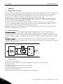
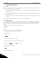
1.2 Brake components
The brake chopper
is an extra IGBT mounted into the NX frequency converters at the time of
manufacturing. Smaller drives (FR4 to FR6 and MF4 to MF6) contain it as standard. If the DC link
voltage increases too much, the brake IGBT turns on and discharges the capacitors through the brake
resistor. The brake chopper in the NX frequency converter ranges is rated for continuous drive rated
power.
The brake resistor
is an external, low impedance resistor. In order to achieve the correct power
handling capacity for a specific application, resistors can be connected in series and parallel, keeping
within the limits in
Table 7.
M
Brake resistor
Brake chopper
nxbr1.fh11
Figure 1. The brake components and their basic connection
1.3 Classes of use
a) Partial use (most typical)
The process requires regular or irregular rapid decelerations, stops or reversings.
b) Continuous use
The motor continuously brakes with constant torque.
c) Combination use
The motor continuously brakes with variable torque.
d) DC-link voltage smoothing
The brake resistor smooths overvoltage spikes from the supply.

Technical data vacon • 3
24-hour support: +358 (0)201 212 575 • Email: vac[email protected]om
2
2. TECHNICAL DATA
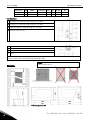
2.1 Standard resistors for partial use
Brake resistors for partial use for the NX ranges for 208…240V, 380…500V and 525…690V supply
voltages can be chosen from the tables below.
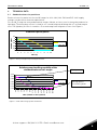
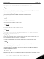
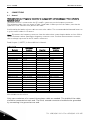
For the NX_5 range we have predefined two ranges of brake resistors, one for heavy duty and one for
light duty. The heavy duty resistor is sized for a 3-second full power braking with a 7-second ramp to
zero. The light duty resistor is rated for a 5-second ramp from full power to zero. See Figure 2.
Predefined power pulses
0
0,2
0,4
0,6
0,8
1
1,2
0 1 2 3 4 5 6 7 8 9 10
Time (s)
Relative power
Heavy duty
Light duty
Figure 2. Heavy and light duty braking definitions.
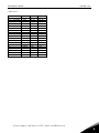
Figure 3. Peak and average power definitions.
Relative power handling capability of the
standard brake resistor ranges
0,00
0,20
0,40
0,60
0,80
1,00
1,20
0 %
2 %
3 %
5 %
7 %
8 %
17 %
25 %
33 %
42 %
50 %
67 %
83 %
100 %
ED% ( based on 120 s period)
Heavy duty
Light duty
Peak power
Average power
=Continuos power

4 • vacon technical data
Tel. +358 (0)201 2121 • Fax: +358 (0)201 2121 205
2
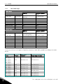
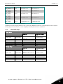
2.1.1
380…500V range
Light duty
Energy
[kJ]
Average power
[kW]
Type code Resistance
5 sec full torque
braking
1 pulse/2 min
BRR 0022 LD 5 63 28 0.24
BRR 0031 LD 5 42 42 0.35
BRR 0045 LD 5 21 84 0.71
BRR 0061 LD 5 14 127 1.06
BRR 0105 LD 5 6,5 273 2.28
BRR 0300 LD 5 3.3 547 4.56
BRR 0520 LD 5 1,4 1270 10,6
BRR 0730 LD 5 0,9 1975 16,5
Heavy duty
Energy
[kJ]
Average power
[kW]
Type code Resistance
3 sec full torque
decreasing to zero in 7s
1 pulse / 2min
BRR 0022 HD 5 63 73 0.61
BRR 0031 HD 5 42 110 0,91
BRR 0045 HD 5 21 220 1.83
BRR 0061 HD 5 14 330 2,74
BRR 0105 HD 5 6,5 710 5,9
BRR 0300 HD 5 3.3 1421 11,8
BRR 0520 HD 5 1,4 3300 27,4
BRR 0730 HD 5 0,9 5132 43
Table 1. Brake resistors for the voltage range 380…500V
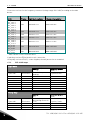
Choose the resistor for all types of frequency converters ( NXL, NXS and NXP) according to the table
below:
Unit
Frame
Light duty
resistor
Heavy duty resistor
NX_ 0003 5
NX_ 0004 5
NX_ 0005 5
NX_ 0007 5
NX_ 0009 5
NX_ 0012 5
FR4 BRR 0022 LD 5 BRR 0022 HD 5
NX_ 0016 5
NX_ 0022 5
FR5 BRR 0022 LD 5 BRR 0022 HD 5
NX_ 0031 5 FR5 BRR 0031 LD 5 BRR 0031 HD 5
NX_ 0038 5
NX_ 0045 5
FR6 BRR 0045 LD 5 BRR 0045 HD 5
NX_ 0061 5 FR6 BRR 0061 LD 5 BRR 0061 HD 5
NX_ 0072 5
NX_ 0087 5
FR7 BRR 0105 LD 5 BRR 0105 HD 5
NX_ 0105 5 FR7 BRR 0105 LD 5 BRR 0105 HD 5
NX_ 0140 5
FR8 BRR 0300 LD 5 BRR 0300 HD 5

Technical data vacon • 5
24-hour support: +358 (0)201 212 575 • Email: vac[email protected]om
2
NX_ 0168 5
NX_ 0205 5 FR8 BRR 0300 LD 5 BRR 0300 HD 5
NX_ 0261 5
NX_ 0300 5
FR9 BRR 0300 LD 5 BRR 0300 HD 5
NX_0385 5
NX_0460 5
NX_0520 5
FR10 BRR 0520 LD 5 BRR 0520 HD 5
NX_0590 5
NX_0650 5
NX_0730 5
FR11 BRR 0730 LD 5 BRR 0730 HD 5
NX_0820 5
NX_0920 5
NX_1030 5
FR12 2 x BRR 0520 LD 5 2 x BRR 0520 HD 5
Table 2. Brake resistors used with drives
Light duty resistor:IP50 with direct wire connection, BRR0022 LD5 has a thermal protection as option.
Heavy duty resistor:IP20/21, connecting box, thermal protection as standard.
2.1.2
208…240V range
Light duty
Energy
[kJ]
Average power
[kW]
Type code Resistance
5 sec full torque
braking
1 pulse/2 min
BRR 0025 LD2
30 12,55 0,10
BRR 0031 LD2
20 18,8 0,16
BRR 0061 LD2
10 38 0,31
BRR 0114 LD2
3,3 114 0,95
BRR 0205 LD2
1,4 269 2,24
Heavy duty
Energy
[kJ]
Average power
[kW]
Type code Resistance
3 sec full torque
decreasing to zero in
7 sec 1 pulse / 2min
BRR 0025 HD2
30 32,6 0,27
BRR 0031 HD2
20 49 0,41
BRR 0061 HD2
10 98 0,81
BRR 0114 HD2
3,3 297 2,47
BRR 0205 HD2
1,4 699 5,81
Table 3. Brake resistors for the voltage range 208…240V

6 • vacon technical data
Tel. +358 (0)201 2121 • Fax: +358 (0)201 2121 205
2
Choose the resistor for the frequency converter (voltage range 208…240V) according to the table
below:
Unit
Frame
Light duty resistor
Heavy duty resistor
NX_ 0003 2
NX_ 0004 2
NX_ 0007 2
NX_ 0008 2
NX_ 0011 2
NX_ 0012 2
FR4 BRR 0025 LD 2 BRR 0025 HD 2
NX_ 0017 2
NX_ 0025 2
FR5 BRR 0025 LD 2 BRR 0025 HD 2
NX_ 0031 2 FR5 BRR 0031 LD 2 BRR 0031 HD 2
NX_ 0048 2
NX_ 0061 2
FR6 BRR 0061 LD 2 BRR 0061 HD 2
NX_ 0075 2
NX_ 0088 2
NX_ 0114 2
FR7 BRR 0114 LD 2 BRR 0114 HD 2
NX_0140 2
NX_0170 2
NX_0205 2
FR8
BRR 0205 LD2 BRR 0205 HD2
NX_0261 2
NX_0300 2
FR9
BRR 0205 LD2 BRR 0205 HD2
Table 4. Brake resistors used with drives
Light duty resistor:IP50 with direct wire connection,
Heavy duty resistor:IP20/21, connecting box, thermal protection as standard.
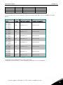
2.1.3
525…690V range
Light duty
Energy
[kJ]
Average power
[kW]
Type code Resistance
5 sec full torque
braking
1 pulse/2 min
BRR 0013 LD 6 100 34 0,28
BRR 0034 LD 6 30 113 0,94
BRR 0052 LD 6 18 188 1,6
BRR 0100 LD 6 9 376 3,1
BRR 0208 LD 6 7 484 4,0
BRR 0416 LD 6 2,5 1355 11
BRR 0590 LD 6 1,7 1993 17
Heavy duty
Energy
[kJ]
Average power
[kW]
Type code Resistance
3 sec full torque
decreasing to zero in
7 sec 1 pulse / 2min
BRR 0013 HD 6 100 88 0,73
BRR 0034 HD 6 30 294 2,4
BRR 0052 HD 6 18 489 4,1

Technical data vacon • 7
24-hour support: +358 (0)201 212 575 • Email: vac[email protected]om
2
BRR 0100 HD 6 9 978 8,1
BRR 0208 HD 6 7 1258 10
BRR 0416 HD 6 2,5 3523 29
BRR 0590 HD 6 1,7 5181 43
Table 5. Brake resistors for the voltage range 525…690V
Choose the resistor for the frequency converter (voltage range 208…240V) according to the table
below:
Unit
Frame
Light duty resistor
Heavy duty resistor
NX_ 0003 6
NX_ 0004 6
NX_ 0005 6
NX_ 0007 6
NX_ 0010 6
NX_ 0013 6
FR6 BRR 0013 LD 6 BRR 0013 HD 6
NX_ 0018 6
NX_ 0022 6
NX_ 0027 6
NX_ 0034 6
FR6 BRR 0034 LD 6 BRR 0034 HD 6
NX_ 0041 6
NX_ 0052 6
FR7 BRR 0052 LD 6 BRR 0052 HD 6
NX_ 0062 6
NX_ 0080 6
NX_ 0100 6
FR8 BRR 0100 LD 6 BRR 0100 HD 6
NX_ 0144 6
NX_ 0170 6
NX_ 0208 6
FR9 BRR 0208 LD 6 BRR 0208 HD 6
NX_0261 6
NX_0325 6
NX_0385 6
NX_0416 6
FR10 BRR 0416 LD 6 BRR 0416 HD 6
NX_0460 6
NX_0502 6
NX_0590 6
FR11 BRR 0590 LD 6 BRR 0590 HD 6
NX_0650 6
NX_0750 6
NX_0820 6
FR12 BRR 0416 LD 6 BRR 0416 HD 6
Table 6. Brake resistors used with drives
Light duty resistor:IP50 with direct wire connection.
Heavy duty resistor:IP20/21, connecting box, thermal protection as standard.

8 • vacon technical data
Tel. +358 (0)201 2121 • Fax: +358 (0)201 2121 205
2
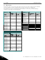
2.2 Other resistors
Should other types of resistors be used, make sure that the resistance is higher than the minimum
resistance defined. The power handling capacity must be sufficient for the application.
The minimum resistances calculated at the trip level (NX_5: 911VDC, NX_2: 437VDC and NX_6:
1200VDC) can be found in the following tables.
380…500V range
208…240V range
Frame
Brake
chopper
I
nom
@
80°C
R
min
[Ω]
Frame
Brake chopper
I
nom
@
80°C
R
min
[Ω]
NX_0003 5…
NX_0022 5
12 63
NX_0003 2...
NX_0025 2
15 30
NX_0031 5 17 42 NX_0031 2 23 20
NX_0038 5…
NX_0045 5
35 21
NX_0048 2…
NX_0061 2
46 10
NX_0061 5 65 14
NX_0075 2...
NX_0114 2
148 3,3
NX_0072 5…
NX_0105 5
111 6.5
NX_0140 2...
NX_0300 2
296 1,4
NX_0140 5...
NX_0300 5
222 3.3
NX_0385 5…
NX_0520 5
570 1.4
NX_0590 5…
NX_0730 5
855 0,9
NX_0820 5
NX_1030 5
2 x 570 2 x 1,4
575…690V range
Frame
Brake
chopper
I
nom
@
80°C
R
min
[Ω]
NX_0004 6...
NX_0013 6
11 100
NX_0018 6…
NX_0034 6
37 30
NX_0041 6…
NX_0052 6
61 18
NX_0061 6…
NX_0100 6
122 9
NX_0125 6…
NX_0208 6
157 7
NX_0261 6…
NX_0416 6
440 2,5
NX_0460 6…
NX_0590 6
647 1.7
NX_0650 6…
NX_0820 6
2x 440 2 x2.5
Table 7. Specification for other types of resistors

Technical data vacon • 9
24-hour support: +358 (0)201 212 575 • Email: vac[email protected]om
2
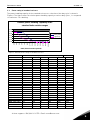
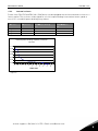
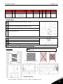
2.3 Power rating of standard resistors
The power handling capacity of the standard resistors as a function of the duty cycle is shown in
Figure 4. The figure shows the relative power handling capacity at various duty cycles, i.e. compared
to continuous 120 s braking.
Figure 4. Relative power rating of standard resistors
Power at different duty cycles based on a 120 sec cycle
100% ED
60% ED
40 % ED
25 % ED
10 % ED
5 % ED
kW
BRR 0025 LD 2
0,10
0,17
0,26
0,42
1,0
2,1
BRR 0031 LD 2
0,16
0,26
0,39
0,63
1,6
3,1
BRR 0061 LD 2
0,31
0,52
0,78
1,3
3,1
6,3
BRR 0114 LD 2
0,95
1,6
2,4
3,8
9,5
19,0
BRR 0205 LD 2
2,2
3,7
5,6
9,0
22
45
BRR 0022 LD 5
0,24
0,39
0,59
0,94
2,4
4,7
BRR 0031 LD 5
0,35
0,59
0,88
1,41
3,5
7,1
BRR 0045 LD 5
0,71
1,2
1,8
2,8
7,1
14,1
BRR 0061 LD 5
1,1
1,8
2,6
4,2
10,6
21
BRR 0105 LD 5
2,3
3,8
5,7
9,1
23
46
BRR 0300 LD 5
4,6
7,6
11,4
18,2
46
91
BRR 0520 LD 5
11
17,6
26
42
106
212
BRR 0730 LD 5
16
27
41
66
165
329
BRR 0013 LD 6
0,28
0,47
0,71
1,13
2,8
5,6
BRR 0034 LD 6
0,94
1,6
2,4
3,8
9,4
18,8
BRR 0052 LD 6
1,6
2,6
3,9
6,3
15,7
31
BRR 0100 LD 6
3,1
5,2
7,8
12,5
31
63
BRR 0208 LD 6
4,0
6,7
10,1
16,1
40
81
BRR 0416 LD 6
11
19
28
45
113
226
BRR 0590 LD 6
17
28
42
66
166
332
BRR 0025 HD 2
0,27
0,45
0,68
1,1
2,7
5,4
BRR 0031 HD 2
0,41
0,68
1,0
1,6
4,1
8,1
Relative power handling capability of the
standard brake resistor ranges
0,00
0,20
0,40
0,60
0,80
1,00
1,20
0 %
2 %
3 %
5 %
7 %
8 %
17 %
25 %
33 %
42 %
50 %
67 %
83 %
100 %
ED% ( based on 120 s period)
Heavy duty
Light duty

10 • vacon technical data
Tel. +358 (0)201 2121 • Fax: +358 (0)201 2121 205
2
BRR 0061 HD 2
0,81
1,4
2,0
3,3
8,1
16,3
BRR 0114 HD 2
2,5
4,1
6,2
9,9
25
49
BRR 0205 HD 2
5,8
9,7
14,5
23
58
116
BRR 0022 HD 5
0,61
1,02
1,52
2,44
6,1
12,2
BRR 0031 HD 5
0,91
1,5
2,3
3,7
9,1
18,3
BRR 0045 HD 5
1,8
3,0
4,6
7,3
18,3
37
BRR 0061 HD 5
2,7
4,6
6,9
11,0
27
55
BRR 0105 HD 5
5,9
9,8
14,8
24
59
118
BRR 0300 HD 5
11,8
19,7
30
47
118
236
BRR 0520 HD 5
27
46
69
110
274
549
BRR 0730 HD 5
43
71
107
171
427
854
BRR 0013 HD 6
0,73
1,2
1,8
2,9
7,3
14,6
BRR 0034 HD 6
2,4
4,1
6,1
9,8
24
49
BRR 0052 HD 6
4,1
6,8
10,2
16,3
41
81
BRR 0100 HD 6
8,1
13,6
20
33
81
163
BRR 0208 HD 6
10
17,4
26
42
105
209
BRR 0416 HD 6
29
49
73
117
293
586
BRR 0590 HD 6
43
72
108
172
431
862

Technical data vacon • 11
24-hour support: +358 (0)201 212 575 • Email: vac[email protected]om
2
2.4 Environment
Surface temperature of the resistor box <80ºC
Maximum ambient temperature 30ºC
Protection class IP20, IP21, IP50
NOTE
: On mounting the resistor package, note the high surface temperature ( up to 200 °C). The
mounting surface must be non-flammable and there must be sufficient free space around the
resistor (100 mm).
The resistors are designed for natural convection cooling in a free space; ensure sufficient ventilation
of the area.

12 • vacon technical data
Tel. +358 (0)201 2121 • Fax: +358 (0)201 2121 205
2
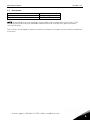
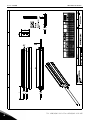
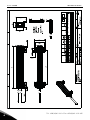
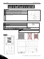
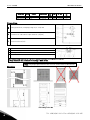
2.5 Thermal protection for the LD resistors
There are two different overtemperature sensors in use – one for the resistors with a
smooth surface and the other for the ones with cooling fins. The larger steel plate
resistors have a thermal supervision built in as standard.
OT1 – for brake resistors with cooling fins.
Thermal supervision OT1
This is intended to be mounted on the lower (connector) end when the resistor is
mounted vertically. It is screwed onto the fins.
Types:
BRR 0114 LD 2
BRR 0031 LD 5
BRR 0034 LD 6
BRR 0205 LD 2
BRR 0045 LD 5
BRR 0052 LD 6
BRR 0061 LD 5
BRR 0100 LD 6
BRR 0025 HD 2
BRR 0105 LD 5
BRR 0206 LD 6
BRR 0031 HD 2
BRR 0300 LD 5
BRR 0061 HD 2 BRR 0013 HD 6
BRR 0114 HD 2
BRR 0022 HD 5
BRR 0034 HD 6
BRR 0205 HD 2
BRR 0031 HD 5
BRR 0045 HD 5
BRR 0061 HD 5

Technical data vacon • 13
24-hour support: +358 (0)201 212 575 • Email: vac[email protected]om
2
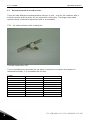
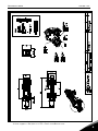
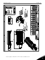
OT2
This thermal supervision is designed for the resistors with a smooth surface. The
thermistor is placed beneath the clip and the clip clipped onto the resistor surface.
Thermal protection and the holder for it
2.5.1
Thermal protection:
The thermal protection in the resistors should be connected to the external Fault input on the drive.

14 • vacon technical data
Tel. +358 (0)201 2121 • Fax: +358 (0)201 2121 205
3
3. CHOICE OF BRAKE RESISTOR
3.1 General
When you choose the brake resistor for your drive, start from the requirements of the process/drive.
The choice of brake resistor is influenced by
a)
the average braking power during one cycle
; this defines the power dissipation required of the
brake resistor
b)
the maximum power dissipation
; this defines the instantaneous power handling capacity of the
brake resistor and
c)
the maximum current of the brake IGBT
; this defines the minimum resistance for the brake
resistor.
Vacon Technical Support will assist you in all matters concerning braking.
3.2 Sizing principles
All rotating parts contain kinetic energy. When the load is braked, the energy difference between the
higher speed and the lower speed must be dissipated somewhere. Some of the energy is used in the
losses of the motor and the frequency converter, but the majority must be dissipated in the brake
resistor.
The energy of a load at speed
n
is given by the formula:
2
2
1
ω
JE =
where
J
is the moment of inertia of the load (in kgm
2
) and
ω
is the rotating speed of the load (in radians/s)
In engineering units
2
3,182
1
JnE =
where
n
is the rotating speed (in 1/min)
The difference between the energy at two speeds is thus
)(
2
1
)(
3,182
1
2
2
2
1
2
2
2
121
ωω
−=−=−=∆ JnnJEEE
The average power required is
t
E
P
∆
=
where
t
is the braking time.

Technical data vacon • 15
24-hour support: +358 (0)201 212 575 • Email: vac[email protected]om
3
If the load has a cycle with a total cycle time
t
c
, the average power of the cycle is
c
t
E
P
∆
=
The chosen resistor must be able to handle this power. If the braking time is longer than 1 minute,
the resistor must be sized for the continuous braking power.
3.2.1
Calculating braking time
The time required to accelerate or brake a load can be calculated as follows:
The basic equation is:
dt
d
JT
ω
=
where
T
is the required torque.
The time required to change the speed of a load is
T
Jt
21
ωω
−
=∆
or the torque required to change the speed in time
t
is
t
JT
21
ωω
−
=
The available torque consists of the torque generated by the motor T
motor
and the braking torque
generated by the load and friction in it T
load
.
loadmotortotal
TTT +=
In many cases the frictional torque is sufficient to brake the load, it might even be too high, so the
motor must drive the load even if the speed is slowing down.
This torque required from the motor should be compared to the rated torque of the motor:
n
P
T 9550=
If the rated torque is higher, the motor can perform the required acceleration/deceleration.
3.2.2
Calculating the moment of inertia
The moment of inertia as ‘seen’ by the motor consists of the motor inertia plus the load inertia,
changed by the gear ratio as follows:
loadmotortot
JgJJ
2
+=
where
g
is the gear ratio, J
motor
is the motor inertia and J
load
is the load inertia. The ratio
g
is > 1 if the
load speed is higher than the motor speed and < 1 if the load speed is lower than the motor speed.

16 • vacon technical data
Tel. +358 (0)201 2121 • Fax: +358 (0)201 2121 205
3
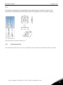
In many cases the moment of inertia of the motor is very small compared to the moment of inertia of
the load. Only in cases where the load turns very slowly (i.e. the gear ratio is low) the motor inertia is
significant.
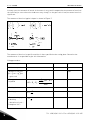
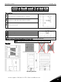
The moment of inertia of typical shapes is shown in Figure 5
Figure 5.
The moment of inertia of a specific machine is often specified on the rating plate. Otherwise the
manufacturer is responsible to give this information.
Sizing procedure:
1. Maximum speed n
1
rpm
2 Minimum speed n
2
rpm
3 Moment of inertia =
loadmotortot
JgJ
J
2
+=
g = gear ratio
J kgm
2
4 Energy to be
dissipated
1000
)(
3,182
1
2
2
2
1
21
nnJ
EEE
−
=−=∆
kJ
5 Braking time t s
6 Braking power
t
E
P
∆
=
kW
7 Determine duty cycle
for braking
t
1
= duration of cycle –
assumption 120 s.
1
t
t
f =

Technical data vacon • 17
24-hour support: +358 (0)201 212 575 • Email: vac[email protected]om
3
8 Determine average
power for the resistor
fPP
ave
=
kW
9 Calculate the relative
power required.
P
res
= peak power of
chosen resistor
res
ave
rel
P
P
P =
%
10 Verify that the pair of
values in 7 and 9 are
within limits for the
chosen resistor – see
Figure 5
7 Calculate the braking
torque required
t
nn
JT
21
105,0
−
××=
Nm
8 Verify motor rated
torque > required
torque
P
M
in kW
n
M
in rpm
M
M
M
n
P
T ×= 9550
Nm
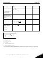
Figure 6. Speed profile of one drive cycle.
t
1
= length of cycle
t
2
= deceleration time
t
3
= stop time
n
1
= minimum speed of motor
n
2
= maximum speed of motor
The relative power handling capability of the standard resistor ranges is shown in the figure below:

18 • vacon technical data
Tel. +358 (0)201 2121 • Fax: +358 (0)201 2121 205
3
Relative power handling capability of the
standard brake resistor ranges
0,00
0,20
0,40
0,60
0,80
1,00
1,20
0 %
2 %
3 %
5 %
7 %
8 %
17 %
25 %
33 %
42 %
50 %
67 %
83 %
100 %
ED% ( based on 120 s period)
Heavy duty
Light duty
Figure 7.
Verify the following:
a) The chosen resistor type can handle the required power (NOTE: As the brake IGBT current is
limited by the device, a resistance with a smaller impedance than the minimum specified for the drive
cannot be used).
b) If this is not the case, the resistor has to be sized specifically for the application. In many cases a
suitable combination of series and parallel connection of standard resistances may be the solution, in
others a special resistor must be defined and manufactured.
Page is loading ...
Page is loading ...
Page is loading ...
Page is loading ...
Page is loading ...
Page is loading ...
Page is loading ...
Page is loading ...
Page is loading ...
Page is loading ...
Page is loading ...
Page is loading ...
Page is loading ...
Page is loading ...
Page is loading ...
Page is loading ...
Page is loading ...
Page is loading ...
-
 1
1
-
 2
2
-
 3
3
-
 4
4
-
 5
5
-
 6
6
-
 7
7
-
 8
8
-
 9
9
-
 10
10
-
 11
11
-
 12
12
-
 13
13
-
 14
14
-
 15
15
-
 16
16
-
 17
17
-
 18
18
-
 19
19
-
 20
20
-
 21
21
-
 22
22
-
 23
23
-
 24
24
-
 25
25
-
 26
26
-
 27
27
-
 28
28
-
 29
29
-
 30
30
-
 31
31
-
 32
32
-
 33
33
-
 34
34
-
 35
35
-
 36
36
-
 37
37
-
 38
38


Vacon nxs User guide
- Type
- User guide
- This manual is also suitable for
Ask a question and I''ll find the answer in the document
Finding information in a document is now easier with AI
Related papers
-
Vacon nxs User manual
-
-
-
-
Vacon CX (Legacy Product) User manual
-
-
-
-
-
Vacon NX IP54 Kit Installation guide
Other documents
-
CnMemory 85963 Datasheet
-
Danfoss NX Cable accessories FR4-8, MF4-6 Installation guide
-
Varta 4103 Datasheet
-
Danfoss VACON NXL (Legacy Product) User guide
-
-
-
Varta Longlife Extra D User manual
-
-
Varta Longlife Extra C User manual
-
Eaton Cutler-Hammer SLX9000 Series User manual