Page is loading ...

Your Guide to the Installation,
Care and maintenance of
T555 and T555L Dual Control
Thermostatic Bath and Shower Mixer
T555 Dual Control Thermostatic Bath and Shower Mixer - 329500
T555L (Lever) Dual Control Thermostatic Bath and Shower Mixer - 329501
1
You’re Guide to the Installation, Care and maintenance of
PERFO RM A
Dual Control Thermostatic
Bath and Shower Mixer
T555 Dual Control Bath and Shower Mixer – 329500
1
You’re Guide to the Installation, Care and maintenance of
PE RFO RM A
T555 and T555L Dual Control
Thermostatic Bath and Shower Mixer
T555 Dual Control Thermostatic Bath and Shower Mixer – 329500
T555L (Lever) Dual Control Thermostatic Bath and Shower Mixer - 329501

Contents
Introduction ......................................................................................................... 3
Product Identification and Spares ....................................................................... 3
Water Regulation Requirements .......................................................................... 4
Pipe Connections ................................................................................................ 4
Water Supply Pressures ...................................................................................... 4
Condition of normal use ...................................................................................... 5
Product Specification .......................................................................................... 5
Pre-Installation Checks ....................................................................................... 5
Flow Regulator Specification .............................................................................. 6
Installation ........................................................................................................... 6
Outlet Connections ............................................................................................. 7
Operation ............................................................................................................. 7
Bath Fill ................................................................................................................ 7
Function of Diverter ............................................................................................. 7
Commissioning .................................................................................................... 7
In Service Testing ................................................................................................ 8
High Pressure Installations Only .......................................................................... 8
Maintenance ........................................................................................................ 9
Mixed Water Temperature ................................................................................. 10
Temperature Setting .......................................................................................... 10
Disassemble for Cleaning .................................................................................. 12
Reassembly of Cartridge ................................................................................... 14
Reassembly of Cartridge into Body .................................................................. 14
Care and Maintenance ...................................................................................... 15
Customer Reference Data ................................................................................. 15
2

3
Introduction
Before installing this product - Pegler Yorkshire recommend the reading of this
document thoroughly and leaving it with the user for future reference.
Product Identification and Spares
3
Introduction
Before installing this product – Pegler Yorkshire recommend that you read this document thoroughly and
leave it with the user for future reference.
Product Identification and Spares
$! #
$! #
$! #
$! #
$! #!
$! #"
$! ##
$! #$
$! #%
$! $
$! $
$! $
$! $
$! $
!!! $! #!
$! $"
$##
21
19
20
4
Water Regulations Requirements
It is important to ensure that the water supplies to your taps and mixers are connected in accordance with the water
regulations (WRAS) requirements and good plumbing practice.
It is Pegler Yorkshires recommendation and good plumbing practice that the supplies of hot and cold water to the
products should be at equal (balanced) pressures in order to provide a consistent flow. Supplies should be from a
common source, either mains or tank fed. If supplies are not equal pressures then single check valves must be fitted
(supplied).
The installation of any thermostatic product must comply with the requirements of the Water Supply (Water Fittings)
Regulations 1999.
Regulation G15.14
G15.14
Submerged inlets to baths or washbasins in any house or domestic situation are considered to be a fluid category 3
risk; they should be supplied with water from a supply or distributing pipe through a double check valve. Submerged
inlets to baths or washbasins in other than a house or domestic situation, and sinks in any location, are considered to
be a fluid category 5 risk and appropriate backflow protection is required for this level of risk.
The shower head of any shower hose pipe should be fitted by a fixed or sliding attachment so that it can only be
discharged at a point not less that 25mm above the spill-over level of the bath tray or fixed appliance. (Shower kit not
supplied)
This product has been designed to function on all types of water systems.
Please Note: If a pump is to be installed to boost gravity supplies please refer to the pump manufactures
instructions.
The hot and cold inlets for any of the products are hot on the left and cold on the right when viewed from the front of
the fitting. It is our recommendation and good plumbing practice that a service valve also (Pegler PB300) should be
installed upstream in the inlet supply lines.
Pipe Connections
IMPORTANT: Before making any inlet pipe connections all supplies MUST be thoroughly flushed to remove any
debris. Failure to do so could result in damage or low flow from the Bath and Shower Mixer. It is a requirement of
Schedule 2, 13 of the Water Supply (Water Fittings) Regulations 1999 that this function is undertaken before it is first
used.
The Thermostatic Bath and Shower Mixer inlet connections are threaded ” BSP
General Installation Notes
• Care must be taken during installation to prevent any risk of damage to the product or injury to installer.
• Installation must be carried out by a qualified and competent person and in accordance with the instructions
supplied.
• Installations must comply with all Local and National Water Authority Regulations, and Building/Plumbing
Regulations.
• Please ensure that you have read and understood all sections of this manual before installation.
Water Supply Pressures
This fitting has been designed to function under the following conditions:
• Minimum supply pressure 0.2 bar
• Maximum dynamic supply pressure 3.0 bar
• Recommended dynamic Pressure 1.5 – 2.0 bar
Generous flow rates are achieved at pressures as low as 0.2 bar. At high pressures it may be necessary to
reduce excessive flow rates by fitting a pressure reducing valve in the supply line before the fitting. Using
the supplied flow regulator in the outlet of the product will assist its performance also, but will not negate
the need for the Pressure Reducing Valve!

Water Regulations Requirements
It is important to ensure that the water supplies to your taps and mixers are connected in accordance
with the water regulations (WRAS) requirements and good plumbing practice.
It is Pegler Yorkshires recommendation and good plumbing practice that the supplies of hot and
cold water to the products should be at equal (balanced) pressures in order to provide a consistent
flow. Supplies should be from a common source, either mains or tank fed. If supplies are not equal
pressures then single check valves must be fitted (supplied).
The installation of any thermostatic product must comply with the requirements of the Water Supply
(Water Fittings) Regulations 1999.
Regulation G15.14
G15.14
Submerged inlets to baths or washbasins in any house or domestic situation are considered to be a
fluid category 3 risk; they should be supplied with water from a supply or distributing pipe through
a double check valve. Submerged inlets to baths or washbasins in other than a house or domestic
situation, and sinks in any location, are considered to be a fluid category 5 risk and appropriate
backflow protection is required for this level of risk.
The shower head of any shower hose pipe should be fitted by a fixed or sliding attachment so that
it can only be discharged at a point not less that 25mm above the spill-over level of the bath tray or
fixed appliance. (Shower kit not supplied)
This product has been designed to function on all types of water systems.
Please Note: If a pump is to be installed to boost gravity supplies please refer to the pump
manufactures instructions.
The hot and cold inlets for any of the products are hot on the left and cold on the right when viewed
from the front of the fitting. It is our recommendation and good plumbing practice that a service
valve also (Pegler PB300) should be installed upstream in the inlet supply lines.
Pipe Connections
IMPORTANT: Before making any inlet pipe connections all supplies MUST be thoroughly flushed
to remove any debris. Failure to do so could result in damage or low flow from the Bath and Shower
Mixer. It is a requirement of Schedule 2, 13 of the Water Supply (Water Fittings) Regulations 1999
that this function is undertaken before it is first used.
The Thermostatic Bath and Shower Mixer inlet connections are threaded ¾” BSP
General Installation Notes
• Caremustbetakenduringinstallationtopreventanyriskofdamagetotheproductorinjuryto
installer.
• Installationmustbecarriedoutbyaqualiedandcompetentpersonandinaccordancewith
the instructions supplied.
• InstallationsmustcomplywithallLocalandNationalWaterAuthorityRegulations,andBuilding/
Plumbing Regulations.
• Pleaseensurethatyouhavereadandunderstoodallsectionsofthismanualbefore
installation.
Water Supply Pressures
This fitting has been designed to function under the following conditions:
• Minimumsupplypressure0.2bar
• Maximumdynamicsupplypressure3.0bar
• RecommendeddynamicPressure1.5–2.0bar
Generous flow rates are achieved at pressures as low as 0.2 bar. At high pressures it may be
necessary to reduce excessive flow rates by fitting a pressure reducing valve in the
supply line before the fitting. Using the supplied flow regulator in the outlet of the
product will assist its performance also, but will not negate the need for the Pressure
Reducing Valve!
4

5
Please note: Products that operate outside these conditions cannot be guaranteed to work/operate by the schemes
type two valve.
Maximum Pressure Differential 5:1
Minimum Temperature (Hot/Mixed) = 10ºC Difference
Conditions for normal use
This Pegler Yorkshire product has been designed to function under the following conditions suitable for use as a type
2 valve
High Pressure Low Pressure
Pressure Drop through Shower for Correct Mixing (bar) 0.1 to 5 0.1 to 5
Maximum Static Pressure (bar) 10 10
Flow Pressure – hot and cold sides (bar) 0.5 to 5 0.1 to 1
Hot Supply Temperature Range (10°C above outlet
temperature)
55 to 65 55 to 65
Cold Supply Temperature Range (°C) Equal to or less
than 25
Equal to or less
than 25
Maximum hot water supply temperature 80°C
(A temperature of 60-65°C is recommended for ablutionary installations)
Please note: A suitable hot water temperature control device should be installed to reduce temperatures exceeding
the above maximum hot water supply temperature.
Please note: Valves operating outside these conditions cannot be guaranteed by the Scheme to operate as Type 2
valves. For Low Pressure tub use a minimum flow pressure of 0.2 bar is required to satisfy the flowrate requirements
of BS EN 1287.
The lists of abbreviations and description below are designated codes used throughout this manual.
HP – High Pressure
LP – Low Pressure
S – Shower
T – Tub
T555 and T555L Dual Control Thermostatic Bath and Shower Mixers are both approved for use in the following
designations
Code Operating Pressure Application
HP-S High Pressure Shower
HP-T High Pressure Bath Tub
LP-S Low Pressure Shower
LP-T Low Pressure Bath Tub
TMV2 Approval Certificate Number: BC480/0509
WRAS Approval Certificate Number: 0907039
Product Specification
T555 Dual Control Thermostatic Bath and Shower Mixer
Pre-Installation Checks
When planning the plumbing for your Bath and Shower Mixer installation, it is recommended that the following
checks are undertaken
• The products are supplied with the hot inlet on the left and cold on the right when viewed from the front. The
connection of hot and cold water must be supplied to the appropriate inlet for these products to work
correctly (the hot side is marked with red mark and the cold with blue!)
• Ensure all pipe work has been thoroughly flushed before any installation takes place. Any debris in the
system will impact on the taps performance and may void warranty.
• Ensure that there is sufficient space to install the product without hampering its operation.
• The levers are fixed by a screw located under the coloured indice on top of the levers. Access to this is
required for removing both handles during maintenance and servicing
5
Please note: Products that operate outside these conditions cannot be guaranteed to work/
operate by the schemes type two valve.
Maximum Pressure Differential 5:1
MinimumTemperature(Hot/Mixed)=10ºCDifference
Conditions for normal use
This Pegler Yorkshire product has been designed to function under the following conditions suitable
for use as a type 2 valve
Maximum hot water supply temperature 80°C
(A temperature of 60-65°C is recommended for ablutionary installations)
Please note: A suitable hot water temperature control device should be installed to reduce
temperatures exceeding the above maximum hot water supply temperature.
Please note: Valves operating outside these conditions cannot be guaranteed by the Scheme to
operate as Type 2 valves. For Low Pressure tub use a minimum flow pressure of 0.2 bar is required
to satisfy the flowrate requirements of BS EN 1287.
The lists of abbreviations and description below are designated codes used throughout this
manual.
HP–HighPressure
LP–LowPressure
S–Shower
T–Tub
T555 and T555L Dual Control Thermostatic Bath and Shower Mixers are both approved for use in
the following designations
TMV2 Approval Certificate Number: BC480/0509
WRAS Approval Certificate Number: 0907039
Product Specification
T555 Dual Control Thermostatic Bath and Shower Mixer
Pre-Installation Checks
When planning the plumbing for your Bath and Shower Mixer installation, it is recommended that
the following checks are undertaken
• Theproductsaresuppliedwiththehotinletontheleftandcoldontherightwhenviewedfrom
the front. The connection of hot and cold water must be supplied to the appropriate inlet for
these products to work correctly (the hot side is marked with red mark and the cold with blue!)
• Ensureallpipeworkhasbeenthoroughlyushedbeforeanyinstallationtakesplace.Anydebris
in the system will impact on the taps performance and may void warranty.
• Ensurethatthereissufcientspacetoinstalltheproductwithouthamperingitsoperation.
• Theleversarexedbyascrewlocatedunderthecolouredindiceontopofthelevers.Accessto
this is required for removing both handles during maintenance and servicing
• TheT555shouldbeinstalledinsuchapositionthatmaintenanceoftheBathandShowerMixer
as well as its valves for commissioning and testing can be undertaken.

Flow Regulator Specification
This product has been designed to function with many water systems and the use of flow regulators
are not required where systems operate below 2.5 bar (balanced pressures). For higher pressure
installations above this limit (see: High Pressure Installations Only)
Performanceiswithopenoutletonbathllermodeat46ºCanddoesnotallowforlossesthrough
pipes or fittings. The flow rates are also based on equal pressure drops.
Recommended Minimum Dynamic Supply Pressure 0.2 bar
Product has been factory preset to a temperature of 46°C primarily for bath fill application only!
The temperature differential required between hot supply and outlet temperature is a minimum of
10°C (for example if the required outlet temperature is 45°C then the incoming hot temperature has
to be minimum 55°C)
Installation
Please note: If pipe work is already installed (via retrofit installation) and it is identified the hot and
cold supply lines are on opposite sides (hot on right). Then these will need to be swapped over,
or suitable flexible connections used to cross the supplies. (A possible reduction in flow could be
experiencedifusedinconjunctionwithexibleinletconnections)
1. Remove the bath panel to gain access to the plumbing connections
2. Familiarize yourself with the location of pipe supplies ensuring you are aware which are the hot
supplies and the cold supplies.
3. Ensure water is turned off and pipes are fully drained.
4. Disconnect both hot and cold supply pipes
5. Unscrew backnuts and remove from the existing fitting or taps
6. Clean the area where the new Bath and Shower Mixer is to be fitted
7. Ensure sealing gasket is located on the underside of the Bath and Shower Mixer before locating
tails through the holes in the bath ware.
8. Secure the Bath and Shower Mixer in place by with the backnuts provided, ensuring that
backnuts are tighten securely beneath the ware.
9. Reconnect the hot and cold supplies and check for leaks.
Please note: It is imperative that the product is not used until it has been commissioned for use.
(see “Commissioning”)
6
• The T555 should be installed in such a position that maintenance of the Bath and Shower Mixer as well as
its valves for commissioning and testing can be undertaken.
Flow Regulator Specification
This product has been designed to function with many water systems and the use of flow regulators are not required
where systems operate below 2.5 bar (balanced pressures). For higher pressure installations above this limit (see:
High Pressure Installations Only)
0
10
20
30
40
50
60
70
0.1 0.2 0.3 0.4 0.5 1 1.5 2 2.5 3
Pressure (bar)
Flow (l/m)
Performance is with open outlet on bath filler mode at 46ºC and does not allow for losses through pipes or fittings.
The flow rates are also based on equal pressure drops.
Recommended Minimum Dynamic Supply Pressure 0.2 bar
Product has been factory preset to a temperature of 46°C primarily for bath fill application only!
The temperature differential required between hot supply and outlet temperature is a minimum of 10°C (for example
if the required outlet temperature is 45°C then the incoming hot temperature has to be minimum 55°C)
Installation
Please note: If pipe work is already installed (via retrofit installation) and it is identified the hot and cold supply lines
are on opposite sides (hot on right). Then these will need to be swapped over, or suitable flexible connections used
to cross the supplies. (A possible reduction in flow could be experienced if used in conjunction with flexible inlet
connections)
1. Remove the bath panel to gain access to the plumbing connections
2. Familiarize yourself with the location of pipe supplies ensuring you are aware which are the hot supplies and
the cold supplies.
3. Ensure water is turned off and pipes are fully drained.
4. Disconnect both hot and cold supply pipes
5. Unscrew backnuts and remove from the existing fitting or taps
6. Clean the area where the new Bath and Shower Mixer is to be fitted
7. Ensure sealing gasket is located on the underside of the Bath and Shower Mixer before locating tails through
the holes in the bath ware.
8. Secure the Bath and Shower Mixer in place by with the backnuts provided, ensuring that backnuts are
tighten securely beneath the ware.
9. Reconnect the hot and cold supplies and check for leaks.
Please note: It is imperative that the product is not
used until it has been commissioned for use. (see
“Commissioning”)
Outlet Connections
The outlet for the shower is ” BSP male thread. This will accept any standard shower hose screwed directly onto
the exposed thread at the rear of the Mixer. Refer to the Francis Pegler luxury showers brochure for a
comprehensive choice of “Waterfall” shower kits. A hose retaining ring is supplied with many Pegler Yorkshire slider
Pressure (bar) 0.1 0.2 0.3 0.5 1.0 1.5 2.0 2.5 3.0
Flow at 46ºC l/m without
Regulator
10.9 14.9 18.2 23.4 33.3 41.1 47.6 53.5 58.8
Flow at 46ºC l/m with High
Pressure Regulator
10.9 14.9 18.2 23.4 33.3 41.1 47.6 23.0 23.0
6
6
• The T555 should be installed in such a position that maintenance of the Bath and Shower Mixer as well as
its valves for commissioning and testing can be undertaken.
Flow Regulator Specification
This product has been designed to function with many water systems and the use of flow regulators are not required
where systems operate below 2.5 bar (balanced pressures). For higher pressure installations above this limit (see:
High Pressure Installations Only)
0
10
20
30
40
50
60
70
0.1 0.2 0.3 0.4 0.5 1 1.5 2 2.5 3
Pressure (bar)
Flow (l/m)
Performance is with open outlet on bath filler mode at 46ºC and does not allow for losses through pipes or fittings.
The flow rates are also based on equal pressure drops.
Recommended Minimum Dynamic Supply Pressure 0.2 bar
Product has been factory preset to a temperature of 46°C primarily for bath fill application only!
The temperature differential required between hot supply and outlet temperature is a minimum of 10°C (for example
if the required outlet temperature is 45°C then the incoming hot temperature has to be minimum 55°C)
Installation
Please note: If pipe work is already installed (via retrofit installation) and it is identified the hot and cold supply lines
are on opposite sides (hot on right). Then these will need to be swapped over, or suitable flexible connections used
to cross the supplies. (A possible reduction in flow could be experienced if used in conjunction with flexible inlet
connections)
1. Remove the bath panel to gain access to the plumbing connections
2. Familiarize yourself with the location of pipe supplies ensuring you are aware which are the hot supplies and
the cold supplies.
3. Ensure water is turned off and pipes are fully drained.
4. Disconnect both hot and cold supply pipes
5. Unscrew backnuts and remove from the existing fitting or taps
6. Clean the area where the new Bath and Shower Mixer is to be fitted
7. Ensure sealing gasket is located on the underside of the Bath and Shower Mixer before locating tails through
the holes in the bath ware.
8. Secure the Bath and Shower Mixer in place by with the backnuts provided, ensuring that backnuts are
tighten securely beneath the ware.
9. Reconnect the hot and cold supplies and check for leaks.
Please note: It is imperative that the product is not
used until it has been commissioned for use. (see
“Commissioning”)
Outlet Connections
The outlet for the shower is ” BSP male thread. This will accept any standard shower hose screwed directly onto
the exposed thread at the rear of the Mixer. Refer to the Francis Pegler luxury showers brochure for a
comprehensive choice of “Waterfall” shower kits. A hose retaining ring is supplied with many Pegler Yorkshire slider
Pressure (bar) 0.1 0.2 0.3 0.5 1.0 1.5 2.0 2.5 3.0
Flow at 46ºC l/m without
Regulator
10.9 14.9 18.2 23.4 33.3 41.1 47.6 53.5 58.8
Flow at 46ºC l/m with High
Pressure Regulator
10.9 14.9 18.2 23.4 33.3 41.1 47.6 23.0 23.0

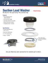
Outlet Connections
The outlet for the shower is ½” BSP male thread. This will accept any standard shower hose
screwed directly onto the exposed thread at the rear of the Mixer. Refer to the Francis Pegler luxury
showers brochure for a comprehensive choice of “Waterfall” shower kits. A hose retaining ring is
supplied with many Pegler Yorkshire slider rail kits, ensuring that the handset cannot be dropped
and submerged in water creating a possible back syphonage problem. See Bylaw 17 (2) B.
InadditionPeglerYorkshirealsooffera6.0l/mshowerregulatorthatcanbeusedinconjunction
with all Pegler Yorkshire showering products. (Order code 343202)
Operation
Operation of product is simple and easy. The Bath and Shower Mixer is supplied maximum factory
setat46ºC(butmayneedadjustingduetoyourspecicsiterequirementsatrsttimeofinstallation
see “Temperature Setting” for details)
However for showering applications we recommend a temperature no greater than 43ºC. It is
therefore essential that when using the shower function of the Bath and Shower Mixer the outlet
temperatureisreducedtoaccommodatealowertemperatureandpreventinjury.
Bath Fill
The purchase of this Bath and Shower Mixer gives you complete confidence that you can both bathe
and shower in perfect safety. Operating the central easy grip handles allow full control of water flow
and temperature adjustment on both the bath and shower outlets. Adjustment on temperature
being the primarily function ensuring that temperature safety is at heart of this product.
The default operation is always the bath fill application and is operated by rotating anti-clockwise
the flow control lever (large lower lever). This will rotate about 100 degrees to full flow.
IMPORTANT: The temperature control lever (smaller upper lever) will rotate also with the flow control
lever but will not change the temperature this needs to be done as an additional action. To get
temperatureadjustmentthetemperaturecontrollevermarkedwiththecolouredindiceshouldbe
used. This will also rotate in an anti-clockwise direction to increase the temperature. It will also
rotatetoastopwhichshouldsupplynomorethan46ºC
Function of Diverter
Pressing down on the diverter at the front of the product (located at the end of the spout) will
change the water flow direction to the shower outlet (located at the rear of the product) If the shower
application is being used, once the water is turned off the Bath and Shower Mixer will always divert
back to bath application ready for next time of use.
Commissioning
Since installed supply conditions may differ from those used in testing and setting the Bath and
Shower Mixers during final inspection, it is necessary to commission the new Bath and Shower
Mixer. The following checks should be used to ensure correct installation of the product.
a) The designation of the thermostatic mixing valve matches the intended application (i.e. if the Bath
and Shower Mixer is supplied at 2 bar then the valve must have HP-T and HP-S designations)
b) The supply pressures are within the valves operating range (see “Conditions for normal use”)
c) The supply temperatures are within the valves operating range (see “Conditions for normal use”)
and comply with the guidance information on the prevention of legionnella.
Please note:Isolation/servicevalves andltersaredesignedandprovidedwithintheBath and
Shower Mixer.
Please note: If all the above conditions are met, proceed to set the temperature as stipulated.
Please note: the supply conditions are not within the parameters for normal use the valve may
still be suitable, but individual engineers must carry out their own risk assessment and satisfy
themselves that the units are still suitable.
7

8
In-service Testing
The purpose of in service testing is to regularly monitor the thermal performance of the thermostatic
valve; deterioration in performance can indicate the need for service work to be carried out on the
system or the Bath Shower Mixer
IMPORTANT: It is a requirement that all TMV2 approved products shall be verified against the
original set temperature results at least once a year. When commissioning/testing is due the
following performance checks should be carried out.
1. Carry out commissioning procedures a to c (see “Commissioning”)
2. Check supply parameters are still within the expected values if not check system for faults.
3. Measure the mixed water temperature at the outlet
4. Carry out the cold water fail-safe shut off test by isolating the cold water to the Bath and
Shower Mixer. (see “Maintenance”). Wait five seconds and if water is still flowing check that
the temperature is below 46°C
5. If there is no significant change to the outlet temperature (±2°C or less change from the original
settings) and the fail safe is functioning then the valve is working correctly and no further service
is required.
6. If the mixed water temperature has changed a significant amount check to ensure in lines filters
are clean, that the non return valves are working and all isolating valves are fully open. If no
faultcanbefoundcheckandrecordthemixedwatertemperaturesandre-adjustmixedwater
temperature to the value in the table (see “Mixed Water Temperature”)
7. If the mixed water temperature exceeds the values of the maximum recorded temperature then
there will be a need for servicing work to be undertaken.
Please note: Ensure any temperature gauges are calibrated before use and the sensing part of
the thermometer probe must be fully submerged in the water that is to be tested and as close to the
outlet as possible. For the T555 Bath and Shower Mixer this should be done so at the open outlet
ofthespoutandnotthroughhose/handsetorshowerhead.
IMPORTANT: The mixed water temperature and the terminal fitting must not exceed 46°C
Notes
If there is a residual flow during the commissioning or the annual verification (cold water supply
isolation test), then this is acceptable providing the temperature of the water seeping from the valve
is no more than 2oC above the designated maximum mixed water outlet temperature setting of the
valve. Temperature readings should be taken at the normal flow rate after allowing for the system to
stabilise. The sensing part of the thermometer probe must be fully submerged in the water that is to
betested.AnyTMVthathasbeenadjustedorservicedmustbere-commissionedandre-testedin
accordance with the manufacturers’ instructions.
High Pressure Installations Only
The Dual control Thermostatic Bath and Shower Mixer works exceptionally well when fitted onto high
pressure systems. Offering a flow rate of over 45 litres per minute at 2.5 bar (balanced pressures).
However for installations of this nature and above Pegler Yorkshire recommend the installation of
aowregulatorttedtotheoutletendoftheproduct–whichwillhelpwiththeperformanceofthe
cold water safety shut failure. Follow the procedures below for installation of the regulator.
1. Ensure the requirement for the regulator is needed by checking and confirming the system
pressure of hot and cold.
2. Turn bath water supplies off, this can be done via primary water supply stop or isolating valves
or the fitted service valves.
3. Using an appropriate spanner on the two flats of the outlet, unscrew the assembly.
4. Onceremoved,takeoutthesealandejecttheowstraightenerbypushingitoutofthechrome
casing.
5. Insert the replacement flow regulator (supplied in the box) into the chrome casing, and screw
back into the spout ensuring the seal is used.
6. Turn the water on and watch for few seconds to ensure that the outlet assembly in not dripping
from the outside of the threads. If this occurs simply tighten a little more.
Please note: If fitting the flow regulator outlet please ensure that the unit is cleaned at regular
intervals. This is especially important in hard water areas.

Application Recommended Mixed Outlet
Water Temperature °C
*** C°44 lliF htaB roF
C°14 rewohS roF
For Wash Basin 41°C
C°83 tediB roF
Service Valve Inner
Maintenance
Please note: Depending in the type of maintenance or servicing to be undertaken a
variety of tools may be required. Included will be pozidriv screwdriver, 50mm spanner
(or suitable adjustable spanner) and small se of adjustable grooved joint pliers or
similar.
1. Carefully remove chrome plated service caps from above the service valves at either end of the
product.Leverthecapoffusingaatscrewdriverorsimilar,positionedintheejectionslotsof
the cap - being careful not to damage the chrome.
2. Turn on the Bath and Shower Mixer using flow control lever, by rotating anti-clockwise, ensuring
that the tap is flowing.
3. Using service valve tool provided. (Spares Code 854464), locate in the castellations and rotate
clockwise to turn off water supply. BOTH sides hot and cold water to be turned off. Once tool is
located rotate until stop is reached. (Pegler Yorkshire recommend hot side first)
Application Recommended Mixed Outlet
Water Temperature °C
*** C°44 lliF htaB roF
C°14 rewohS roF
For Wash Basin 41°C
C°83 tediB roF
Insert edge of coin into
groove and twist, taking
care not to slip
9
9
3. Using service valve tool provided. (Spares Code 854464), locate in the castellations and rotate clockwise to
turn off water supply. BOTH sides hot and cold water to be turned off. Once tool is located rotate until stop is
reached. (Pegler Yorkshire recommend hot side first)
4. At this point the Bath and Shower Mixer has been isolated of water
5. Rotate anti-clockwise the service valves inner using a recommended 12mm socket drive spanner.
Please note: Ensure outer does not follow the inner - if it does it will open the waterway again. If required, use a flat
screwdriver or similar and locate in castellations this will help to hold in place the outer service valve body while
unscrewing the inner.
6. Once unscrewed; lift service valve inner assembly out of the body (if a vacuum is making this difficult to
remove, grip on the flats of the hexagon with the end of a pair of adjustable groove joint pliers and lift)
7. After removing the service valve inner assemblies, they can be disassembled for cleaning or replacing parts.
The filter retaining cap can be removed by inserting edge of coin or similar and simply twist.
1. Please note: If doing this, place the assembly on a hard, non slippery surface being careful not to hurt
yourself.
2. Once removed the parts can now been cleaned or left to soak. Descale using limescale remover, warm
water or similar.
Insert edge of coin
into groove and
twist, taking care not
to slip
Service Valve Inner
4. At this point the Bath and Shower Mixer has been isolated
of water
5. Rotate anti-clockwise the service valves inner using a
recommended 12mm socket drive spanner.
Please note: Ensure outer does not follow the inner - if
it does it will open the waterway again. If required, use a
flat screwdriver or similar and locate in castellations this
will help to hold in place the outer service valve body while
unscrewing the inner.
6. Once unscrewed; lift service valve inner assembly out of
the body (if a vacuum is making this difficult to remove,
grip on the flats of the hexagon with the end of a pair of
adjustablegroovejointpliersandlift)
7. After removing the service valve inner assemblies, they can be disassembled for cleaning or
replacing parts. The filter retaining cap can be removed by inserting edge of coin or similar and
simply twist.
1. Please note: If doing this, place the assembly on a hard, non slippery surface being careful
not to hurt yourself.
2. Once removed the parts can now been cleaned or left to soak. Descale using limescale remover,
warm water or similar.

3. When the components have been cleaned thoroughly, reassemble as found (the filter and
retaining ring should be pressed on until solid and square to the rest of the service valve inner
body).
Please note: Do not replace the service valve inner into the tap without the non-return valves or
filters fitted!
4. Re-grease the ‘o’ rings on the brass body using WRAS approved silicone grease. Replace
service valve inner assemblies into service valve outer
5. Using the same 12mm spanner, drive the service valve inners down (clockwise) until home then
rotate anti-clockwise about ¼ turn to help maintain them free of sticking.
6. Only when ‘both’ service valve inners are re-assembled into the body; using the service valve
tool rotate the service valve outers anti-clockwise (starting with the cold side) until they reach
the upper stops. This will open the waterway to the main workings of the tap and water should
start flowing from the outlet.
7. Shut off water (rotating flow control handle clockwise to stop)
8. Returnservicevalvecapstotheiroriginallocation(makingsuretheslotsforejectionare
pointing away from the front of the tap, but accessible by a screwdriver)
Mixed Water Temperature
Aftercommissioningoranymaintenance/servicingit’simperativethatthewatertemperaturesare
checkedinaccordancewiththetablebelow.Themethodofadjustmentoftemperatureiscovered
later in this manual (see “Temperature Setting”)
*** Please note: The mixed water temperature and the terminal fitting must not exceed 46°C.
The maximum mixed water temperature can be 2°C above the recommended maximum set outlet
temperature of 44°C.
Please note: If there is a residual flow during the commissioning or the annual verification (cold
water supply isolation test), then this is acceptable providing the temperature of the water seeping
from the valve is no more than 2oC above the designated maximum mixed water outlet temperature
setting of the valve.
IMPORTANT: 46°C is the maximum water temperature from the bath tap. The temperature
takes account of the allowable temperature tolerances inherent in thermostatic mixing valves and
temperature losses in metal baths It is not a safe bathing temperature for adults or children.
The British Burns association recommend 37 to 37.5°C as a comfortable bathing temperature for
children. In premises covered by the Care Standards Act 2000, the maximum mixed water outlet
temperature is 43°C
Temperature Setting
If the Bath and Shower Mixer however has operated correctly for some time previous but no longer
performs to an acceptable level then it may require servicing/cleaning. (see “Maintenance”)
whereby the following servicing procedure should be adopted.
If the temperatures of the Bath and Shower Mixer immediately falls out of what are specified for its
individual applications then it may be the result of incorrect installation. Please refer to installation
and site requirements.
10
10
3. When the components have been cleaned thoroughly, reassemble as found (the filter and retaining ring
should be pressed on until solid and square to the rest of the service valve inner body).
Please note: Do not replace the service valve inner into the tap without the non-return valves or filters fitted!
4. Re-grease the ‘o’ rings on the brass body using WRAS approved silicone grease. Replace service valve
inner assemblies into service valve outer
5. Using the same 12mm spanner, drive the service valve inners down (clockwise) until home then rotate anti-
clockwise about turn to help maintain them free of sticking.
6. Only when ‘both’ service valve inners are re-assembled into the body; using the service valve tool rotate the
service valve outers anti-clockwise (starting with the cold side) until they reach the upper stops. This will
open the waterway to the main workings of the tap and water should start flowing from the outlet.
7. Shut off water (rotating flow control handle clockwise to stop)
8. Return service valve caps to their original location (making sure the slots for ejection are pointing away from
the front of the tap, but accessible by a screwdriver)
Mixed Water Temperature
After commissioning or any maintenance/servicing it’s imperative that the water temperatures are checked in
accordance with the table below. The method of adjustment of temperature is covered later in this manual (see
“Temperature Setting”)
Application Recommended Mixed Outlet
Water Temperature °C
For Bath Fill 44°C ***
For Shower 41°C
*** Please note: The mixed water temperature and the terminal fitting must not exceed 46°C. The maximum mixed
water temperature can be 2°C above the recommended maximum set outlet temperature of 44°C.
Please note: If there is a residual flow during the commissioning or the annual verification (cold water supply
isolation test), then this is acceptable providing the temperature of the water seeping from the valve is no more than
2
o
C above the designated maximum mixed water outlet temperature setting of the valve.
IMPORTANT: 46°C is the maximum water temperature from the bath tap. The temperature takes account of the
allowable temperature tolerances inherent in thermostatic mixing valves and temperature losses in metal baths It is
not a safe bathing temperature for adults or children. The British Burns association recommend 37 to 37.5°C as
a comfortable bathing temperature for children. In premises covered by the Care Standards Act 2000, the maximum
mixed water outlet temperature is 43°C
Temperature Setting
If the Bath and Shower Mixer however has operated correctly for some time previous but no longer performs to an
acceptable level then it may require servicing/cleaning. (see “Maintenance”) whereby the following servicing
procedure should be adopted.
If the temperatures of the Bath and Shower Mixer immediately falls out of what are specified for its individual
applications then it may be the result of incorrect installation. Please refer to installation and site requirements.
The following set of tests should be carried out
a) Record the temperature of the hot and cold inlet water supplies
b) Record the temperature of the mixed water at the largest draw off flow rate.
c) Record the temperature of the mixed water at a smaller draw of flow rate, which shall be measured
d) Isolate the cold water supply to the valve body and monitor the mixed water temperature
e) Record the maximum temperature achieved as a result of point (d) and the final temperature
f) Record the equipment, thermometer etc used for the measurements.
Re-setting the maximum temperature is not advisable; however the maximum blend temperature should be limited to
ensure no undesirable temperatures are experienced. If adjustment is required then the following procedures should
be adopted:
1. Shut the water off to the Bath and Shower Mixer and clean appropriate filters positioned in the service valves
(see “Maintenance”)
2. Using flow control lever, open water flow to its maximum (rotate anti-clockwise until it hits its limit)
3. Keep temperature at its coldest by rotating the temperature control lever (rotate clockwise until it hits its limit)

The following set of tests should be carried out
a) Record the temperature of the hot and cold inlet water supplies
b) Record the temperature of the mixed water at the largest draw off flow rate.
c) Record the temperature of the mixed water at a smaller draw of flow rate, which shall be
measured
d) Isolate the cold water supply to the valve body and monitor the mixed water temperature
e) Record the maximum temperature achieved as a result of point (d) and the final temperature
f) Record the equipment, thermometer etc used for the measurements.
Re-setting the maximum temperature is not advisable; however the maximum blend temperature
shouldbelimitedtoensurenoundesirabletemperaturesareexperienced.Ifadjustmentisrequired
then the following procedures should be adopted:
1. Shut the water off to the Bath and Shower Mixer and clean appropriate filters positioned in the
service valves (see “Maintenance”)
2. Using flow control lever, open water flow to its maximum (rotate anti-clockwise until it hits its
limit)
3. Keep temperature at its coldest by rotating the temperature control lever (rotate clockwise until
it hits its limit)
4. Remove indice by insert a thin screwdriver through the centre and lift off (damage to the indice
will occur!). A new indice is included in the service pack.
5. Unscrew brass pozi-driv screw and remove temperature control lever.
6. Nextusingtemperaturecontrolleverandre-locateitloosely–justenoughtorotatethespindle
as required.
7. Usinganelectronictemperaturegaugeundertheconstantlyowingwater,adjustthevalve
spindle gradually until the outlet temperature of 46°C is reached.
• Rotateclockwiseforcoldertemperatures
• Rotateanti-clockwisetoincreasetemperatures
Please note: Ensure any temperature gauges are calibrated before use and the sensing part of
the thermometer probe must be fully submerged in the water that is to be tested and as close to
the outlet as possible.
Please note: Temperature readings should be taken at the normal flow rate after allowing for the
systemtostabilisebeforecontinuingwiththetemperatureadjustmentandnextsteps.
8. While the above procedure allows for the water to stabilise, the internal ‘o’ ring in the flow control
handle can be re lubricated and then refitted.
9. To set the upper limit, refit the temperature control lever correctly by simply pushing home.
Locate so that the pin hits the shoulder of the flow control handle. Do not however screw back
in place!
10.Turnthetemperaturecontrolleverdown,thenupagaintothestop/limitsmakingsurethatwhen
the temperature stabilises it is no more than 46°C.
11. If the temperature is higher or lower than 46°C, lift the temperature control handle off the spindle
againandmoveitonesplineatatimetocompletethenitetemperatureadjustment.
9
Please note: If there is a residual flow during the commissioning or the annual verification (cold water supply
isolation test), then this is acceptable providing the temperature of the water seeping from the valve is no more than
2
o
C above the designated maximum mixed water outlet temperature setting of the valve.
IMPORTANT: 46°C is the maximum water temperature from the bath tap. The temperature takes account of the
allowable temperature tolerances inherent in thermostatic mixing valves and temperature losses in metal baths It is
not a safe bathing temperature for adults or children. The British Burns association recommend 37 to 37.5°C as
a comfortable bathing temperature for children. In premises covered by the Care Standards Act 2000, the maximum
mixed water outlet temperature is 43°C
Temperature Setting
If the Bath and Shower Mixer however has operated correctly for some time previous but no longer performs to an
acceptable level then it may require servicing/cleaning. (see “Maintenance”) whereby the following servicing
procedure should be adopted?
If the temperatures of the Bath and Shower Mixer immediately falls out of what are specified for its individual
applications then it may be the result of incorrect installation. Please refer to installation and site requirements.
The following set of tests should be carried out
a) Record the temperature of the hot and cold inlet water supplies
b) Record the temperature of the mixed water at the largest draw off flow rate.
c) Record the temperature of the mixed water at a smaller draw of flow rate, which shall be measured
d) Isolate the cold water supply to the valve body and monitor the mixed water temperature
e) Record the maximum temperature achieved as a result of point (d) and the final temperature
f) Record the equipment, thermometer etc used for the measurements.
Re-setting the maximum temperature is not advisable; however the maximum blend temperature should be limited to
ensure no undesirable temperatures are experienced. If adjustment is required then the following procedures should
be adopted:
1. Shut the water off to the Bath and Shower Mixer and clean appropriate filters positioned in the service valves
(see “Maintenance”)
2. Using flow control lever, open water flow to its maximum (rotate anti-clockwise until it hits its limit)
3. Keep temperature at its coldest by rotating the temperature control lever (rotate clockwise until it hits its limit)
4. Remove indice by insert a thin screwdriver through the centre and lift off (damage to the indice will occur!). A
new indice is included in the service pack.
5. Unscrew brass pozi-driv screw and remove temperature control lever.
6. Next using temperature control lever and re-locate it loosely – just enough to rotate the spindle as required.
7. Using an electronic temperature gauge under the constantly flowing water, adjust the valve spindle gradually
until the outlet temperature of 46°C is reached.
• Rotate clockwise for colder temperatures
• Rotate anti-clockwise to increase temperatures
Please note: Ensure any temperature gauges are calibrated before use and the sensing part of the thermometer
probe must be fully submerged in the water that is to be tested and as close to the outlet as possible.
Please note: Temperature readings should be taken at the normal flow rate after allowing for the system to stabilise
before continuing with the temperature adjustment and next steps.
11

Please note:Ensurestops/limitsarereachedandtemperatureislefttosettlewhencheckingthe
maximum temperatures.
• Rotateclockwiseforhottertemperature
• Rotateanti-clockwiseforcoldertemperatures
12. Once replaced and fitted to the correct maximum temperature settings, place the brass pozi-driv
screw back into the bore and screw down until handle is secure.
IMPORTANT: Do not over tighten screw as this will have a direct impact on ease of handle
operation
13. Test the tap to the specified cold water shut off tests. (see “In-Service Testing”) If everything
passes, turn the temperature lever to cold, close the flow control handle to the off position. Then
fit the new indice.
IMPORTANT: Any TMV that has been adjusted or serviced must be re-commissioned and re-
tested in accordance with the manufacturers’ instructions.
Disassemble for Cleaning
The action of the service valves complete with filters should eliminate any debris getting into the
mechanical part of the thermostat. In the unlikely event that the cartridge needs to be stripped for
additionalcleaning/re-greasingortoreplaceworkingpartsthefollowingproceduremustbetaken.
1. Carefully remove chrome plated service caps from above the service valves at either end of the
product.Leverthecapoffusingaatscrewdriverorsimilar,positionedintheejectionslotsof
the cap - being careful not to damage the chrome.
2. Turn on the Bath and Shower Mixer using flow control lever, by rotating anti-clockwise, ensuring
that the tap is flowing.
3. Using service valve tool (provided), locate in the castellation and rotate clockwise to turn off both
supplied of water. Rotate until stop is reached. (Pegler Yorkshire recommend hot side first)
4. At this point the Bath and Shower Mixer has been isolated of water
5. Remove indice in the centre of the handles by insert a thin screwdriver through the centre and
lift off. A new indice is included in the service pack.
6. Unscrew brass pozi-driv screw and remove
7. Lift off both the levers
8. Carefully unscrew chrome plated head and remove
9. Lift out cartridge assembly, ensuring the base seal is attached to the base of the cartridge
10. Unscrew and remove capnut using appropriate spanner. If required hold around upper section of
body (as indicated below) with a strap type oil filter remover or boa.
12

IMPORTANT:Makesurethegroovesofthepliers/spannerorsimilarholdbothpillarssecurely!
Holding the valve upright (as shown)
13. Using an appropriate spanner, unscrew the head assembly from the valve body anti-clockwise.
14.Carefullyliftouttheshuttle/elementassemblyusingapairofsnipenosepliers,onlygrippingon
one of the shuttle ribs
IMPORTANT: Do not hold the element piston or the outer wall of the plastic shuttle.
15. Turn upside down to drop the spring and the support disc out.
16. Once removed the parts can now been cleaned or left to soak. Descale using limescale remover,
warm water or similar.
17. Examine all seals and replace if necessary; maintenance kits are available from Pegler Yorkshire
technical.
18. Use WRAS approved silicone based grease on all seals (use a light smear only on the shuttle)
and a more liberal smear on the course thread of the spindle housing. (Spares code for
Grease is 854476)
13
Remove head assembly using
flow control lever located on
the hexagon.
Hold across flats of pillars
usingadjustablespanner
Hold upper section
of body here
13
12. To unscrew the valve head from the valve assembly, hold the flats of the pillars using adjustable grooved
joint pliers / spanner or similar
IMPORTANT: Make sure the grooves of the pliers / spanner or similar hold both pillars securely! Holding the valve
upright (as shown)
13. Using an appropriate spanner, unscrew the head assembly from the valve body anti-clockwise.
14. Carefully lift out the shuttle/element assembly using a pair of snipe nose pliers, only gripping on one of the
shuttle ribs
IMPORTANT: Do not hold the element piston or the outer wall of the plastic shuttle.
15. Turn upside down to drop the spring and the support disc out.
16. Once removed the parts can now been cleaned or left to soak. Descale using limescale remover, warm
water or similar.
17. Examine all seals and replace if necessary; maintenance kits are available from Pegler Yorkshire technical.
18. Use WRAS approved silicone based grease on all seals (use a light smear only on the shuttle) and a more
liberal smear on the course thread of the spindle housing. (Spares code for Grease is 854476)
Reassembly of Cartridge
1. Make sure the valve body is kept upright, with the splined bore at the top during reassembly.
2. Insert the spring
3. Insert the element support disc; making sure the step is facing downwards and locates in the inner diameter
of the spring
Remove head assembly using
flow control lever located on
the hexagon.
Hold across flats of pillars using
adjustable grooved joint pliers /
spanner or similar
11. Using flow control handle unscrew anti
clockwise valve assembly from outer
cartridge body.
12. To unscrew the valve head from the valve
assembly, hold the flats of the pillars using
adjustablegroovedjointpliers/spannerorsimilar

IMPORTANT:
TO KEEP
CENTRAL
CROSS
SECTIONAL
VIEW
14
IMPORTANT: Do not get any grease on the element! If you do, make
sure it is cleaned off thoroughly before replacing into the valve body! Any
grease on the element reduces performance!
4. Carefully replace down the centre of the valve body, threading the
element body through the hole in the centre of the support disc
Equal spaced gaps here!
Reassembly of Cartridge
1. Make sure the valve body is kept upright, with the splined bore at the top during reassembly.
2. Insert the spring
3. Insert the element support disc; making sure the step is facing downwards and locates in the
inner diameter of the spring
5. Press the top of the element a few times to make sure the shuttle and element spring are running
free and everything is aligned.
6. Pick up head assembly and turn upside down. Look at the inner section twist the spindle and you
will see the centre move up and down. Rotate the spindle until the inner raised ring is approximately
the same height at the head outer face.
7. Screw head into valve body making sure it is on centre with the element piston. Turn the head
until it meets the stop, and then drive it down.
8. Once driven down, turn the valve on its side and look in the top two slots and you should see the
shuttle with a gap.
IMPORTANT: Twist the spindle until there are two gaps, one above and one below the shuttle and they
are approximately equal in height.
9. Re-insert the valve into the body and screw down using the flow control handle until the valve is
seated.
10. Replace the brass capnut and screw down to the stop
11. Ensure the washer is attached to the underneath of the cartridge body and lined up in the correct
orientation (a small dab of grease may help to keep washer aligned when fitted to the cartridge)
Reassembly of Cartridge into Body
1. Make sure the washer is attached to the base of the cartridge correctly and locate into bore of
tap ensuring that the location pin is positioned in the matting hole at the seat of the bore.
2. Drive down the chrome plated head until you hit the metal to metal stop making sure cartridge
is held concentric with the body when doing so.
3. With the large flow control lever, open then close the valve to its off position (rotate clockwise
until it hits its limit).
4. Locateleveronthevalvemakingsuretheleverislinedupwithdiverter/spout

Customer Reference Data
Date of Purchase .......................................................................................................
Supplier .....................................................................................................................
Supplier Tel. No. ........................................................................................................
Model Type ......................................... T555-329500 .................................................
Model Type ......................................... T555L-329501 ...............................................
Date of Installation .....................................................................................................
Outlet Temperature
(after first commissioning) ..............................................................
Serial Number
(found underneath the spout) .................................................................
Installer ......................................................................................................................
Installer Contact Details ............................................................................................
.................................................................................................................................
.................................................................................................................................
Date of Service #1 .....................................................................................................
Date of Service #2 .....................................................................................................
Date of Service #3 .....................................................................................................
Date of Service #4 .....................................................................................................
Date of Service #5 .....................................................................................................
5. Continue rest of reassembly by first following instructions in Maintenance.
6. Next complete the instruction in Temperature Setting.
Care & Maintenance
To maintain the surface finishes, simply wipe occasionally with a mild detergent on a soft damp
cloth. Dry using a soft cloth, never use abrasive cleansers or chemical household cleaners, and avoid
contact with concentrated bleach. Pegler Yorkshire products are manufactured to the highest of
standards and should require little or no maintenance.
In the unlikely event of any spare part requirements, please visit our website:
www.pegleryorkshire.co.uk or contact your nearest stockist or the Pegler Yorkshire Sales Office,
St Catherine’s Avenue, Doncaster. DN4 8DF, telephone 0800 1560010, fax 0808 1561011
or the Pegler Yorkshire Technical Office on telephone 0800 1560050, fax 0808 1561012
15
15
9. Re-insert the valve into the body and screw down using the flow control handle until the valve is seated.
10. Replace the brass capnut and screw down to the stop
11. Ensure the washer is attached to the underneath of the cartridge body and lined up in the correct orientation
(a small dab of grease may help to keep washer aligned when fitted to the cartridge)
Reassembly of Cartridge into Body
1. Make sure the washer is attached to the base of the cartridge correctly and locate into bore of tap ensuring
that the location pin is positioned in the matting hole at the seat of the bore.
2. Drive down the chrome plated head until you hit the metal to metal stop making sure cartridge is held
concentric with the body when doing so.
3. With the large flow control lever, open then close the valve to its off position (rotate clockwise until it hits its
limit).
4. Locate lever on the valve making sure the lever is lined up with diverter/spout
T555 T555L
5. Continue rest of reassembly by first following instructions in Maintenance
6. Next complete the instruction in Temperature Setting.
Care & Maintenance
To maintain the surface finishes, simply wipe occasionally with a mild detergent on a soft damp cloth. Dry using a
soft cloth, never use abrasive cleansers or chemical household cleaners, and avoid contact with concentrated
bleach. Pegler Yorkshire products are manufactured to the highest of standards and should require little or no
maintenance. In the unlikely event of any spare part requirements, please visit our website:
www.pegleryorkshire.co.uk or contact your nearest stockist or the Pegler Yorkshire Sales Office, St Catherine’s
Avenue, Doncaster. DN4 8DF, telephone 0800 1560010, fax 0808 1561011 or the Pegler Yorkshire Technical Office
on telephone 0800 1560050, fax 0808 1561012
Customer Reference Data
Date of Purchase……………………………………………….………
Supplier……………………………………………………..……………
Supplier Tel. No…………………………………………….…………..
E
q
ual s
p
aced
g
a
p
s here!

LUXURY TAP SOLUTIONS
Also available from
Pegler Yorkshire:
Our brands:
Pegler Yorkshire
Pegler Yorkshire Group Limited
St. Catherine’s Avenue, Doncaster,
South Yorkshire,
DN4 8DF, England.
Tel: 0844 243 4400 Fax: 0844 243 9870
Registered in England Company No. 00401507
Registered Office: Haigh Park Road, Stourton, Leeds,
West Yorkshire, LS10 1RT, England.
All brand names and logo styles are registered trademarks.
Maintaining a policy of continual product development,
Pegler Yorkshire reserves the right to change specifications, design
and materials of products listed in this publication without prior notice.
UK sales
Free Phone: 0800 156 0010
Free Fax: 0808 156 1011
Email: uk.sales@pegleryorkshire.co.uk
Export
Tel: +44 (0) 1302 855 656
Fax: +44 (0) 1302 730 513
Email: export@pegleryorkshire.co.uk
Technical Help
Free Phone: 0800 156 0050
Free Fax: 0808 156 1012
Email: tech.help@pegleryorkshire.co.uk
Brochure Hotline
Free Phone: 0800 156 0020
Free Fax: 0808 156 1011
Email: info@pegleryorkshire.co.uk
www.pegleryorkshire.co.uk
/