Page is loading ...

SPOA3T-5/5AP/5AF
S & M &C
(700 Series)
Two Post Surface Mounted Lifts
Installer: Please return this booklet to literature package and give to lift owner/operator.
O
P
E
R
A
T
I
O
N
&
M
A
I
N
T
E
N
A
N
C
E
M
A
N
U
A
L
O
P
E
R
A
T
I
O
N
&
M
A
I
N
T
E
N
A
N
C
E
M
A
N
U
A
L
OM-SPO-3
Rev.A 15/02/2018
© Rotary Lift, All rights reserved
SJ180205


Table of Contents
1. Introduction ................................................................5
1.1 About this operating manual ....................................5
1.2 Warning and information symbols ...........................5
1.3 Intended use ...........................................................7
1.4 Incorrect use, incorrect behavior ............................ 7
1.5 Internal accident, health and safety, and environme-
ntal information ........................................ 7
2. Safety ............................... .......................... ....8
2.1 Operators ..................................................................8
2.2 Basic safety requirements ........................................8
2.3 Permitted axle loads and weight distribution ........ 8
2.4 Ban on unauthorized modications or alterations ......9
2.5 Experts, competent persons ......................................9
2.6 Maintenance contractors, installation staff ................10
2.7 Safety inspections by competent persons ................10
2.8 Obligations of the plant operator ................................11
3. The 2-Post Lift ................................................12
3.1 Overview of parts ......................................................12
3.2 Work area, danger zones .........................................13
3.3 Safety mechanisms ..................................................14
3.4 Control unit ........................................................16
4. Operation .......................................................17
4.1 Before loading ........................................................17
4.2 Loading .............................................17
4.3 To rise lift .......................... ......................................18
4.4 While using lift...........................................................18
4.5 Before lowering lift......... ...........................................18
4.6 To lower lift................................................................18
4.7 Unloading .................................................................19
4.8 Power off....................................................................19
5. Problems, causes, actions.............................19
5.1 Troubleshooting by the operator ..............................19
5.2 Troubleshooting by authorized maintenance contractors
...................................................................................... ....20
6. Authorized lowering .......................................22
7. Technical data .................................................23
8. Cleaning ...........................................................29
9. Maintenance and repair ..................................29
9.1 Qualication of maintenance and repair staff ...........29
9.2 Maintenance and repair safety regulations ............. .29
9.3 Maintenance work ...........................................30
9.4 Approved hydraulic oils ............................................32
9.5 Check, rell, change the hydraulic oil .......................33
9.6 Repair work (Repairs) ..............................................34
10.Transport, Storage ...................................35
10.1 Transport .................................................................36
10.2 Ofoading..................................................................36
10.3 Storage .....................................................................36
11.Assembly ........................................................36
11.1 Assembly safety instructions ................................. 36
11.2 Quick assembly instructions ................ ...................37
11.3 Site specications ................................................... 37
11.4 Installation preparations ..........................................37
11.5 Prepare the columns ...............................................37
11.6 Prepare the overhead assembly...............................39
11.7 Assemble the hydraulics module..............................41
11.8 Assemble the equalizing cables............. .................43
11.9 Assemble the locking latch cables for M version......46
11.10 Assemble the electrical connections.......................47
11.11 Installing Gaskets ,web cover andwire chase.........52
11.12 Installing the arms and restraints ..........................53
11.13 Installing others......................................................54
12. Commissioning .............................................56
12.1 Check Operation.....................................................56
12.2 Test the hydraulic system .......................................56
12.3 Oil bleeding.............................................................56
3

12.4 Checking and Adjusting Equailzer Cables.............56
12.5 Checking and Adjusting Latch cable for M
series...............................................................................56
12.6 Locking Latch Engagement Test ..........................56
13. Disassembly ...................................................58
14. Disposal ..........................................................58
14.1 Environmental procedures for disposal ...................58
14.2 Packaging ................................................................58
14.3 Oils, grease, and other chemical substances ..........58
14.4 Metals / Electronic waste .........................................58
ANNEX
•
SPOA3TS/C/M
Hydraulic circuit diagram, Electric wiring diagram,
Parts break down, spare parts list.
•
Protocol of installation
•
Completion certicate
•
Maintenance schedule: Instructions for conducting
visual inspections and function testing
•
Inspection log
•
Master sheet for vehicle lift
•
Test report
4

1. Introduction
1.1 About this operating manual
The post lift conforms to state of the art technolo-
gyand complies with the applicable occupational
health & safety and accident prevention regulations.
Notwithstanding, improper use or use other than that
which is intended may result in a risk of fatal or
physical injury to the user or third parties and may
also result in damage to property.
It is therefore imperative that the relevant people
carefully read and understand this operating manu-
al. Read the instructions carefully to prevent incor-
rect use, potential hazards and damage. The post
lift should always be operated according to regula-
tions.
Please note the following:
• The operating manual must be kept near the lift
and be easily accessible for all users.
• This operating manual provides information on
the two post lifts SPOA3TS/C/M-5,SPOA3TS/C
/M-5AP,SPOA3TS/C/M-5AF variant with column
extension EH0,EH1,EH2.
• Make sure that you have read and understood
Chapter 2, Safety and also the operating
instructions supplied with the machine.
• We assume no liability for damage and opera-
tional breakdowns which may occur as a result of
non-compliance with the instructions contained
within this operating manual.
• Installation and commissioning of the lifts is
described in detail in Chapters 11 to 12.
Installation may only be carried out by authorized
installation specialists and qualied electricians.
• If you should run into difculties please contact
a specialist, our customer service or spare parts
department or one of our representatives.
• Illustrations may differ from the supplied version
of the machine. Functions or processes to be
carried out remain the same.
Disclaimer:
We assume no responsibility for printing errors,
mistakes and technical changes.
The brands and trademarks mentioned in this
document refer to their owners or the products
thereof.
1.2 Warning and information symbols
1.2.1Symbols in this documentation
Warnings are identied by the following
symbols,depending on the hazard classication.
Be especially aware of safety and hazards when
working in situations identied by warning symbols.
Comply with the occupational health & safety
and accident prevention regulations which are
applicable in your country.
Risk of death or injury
Direct threat to life and health
of people. Non-compliance may
lead to death or serious injury.
Risk of death or injury
Potential risk to life and health
of people. Non-compliance may
lead to serious or critical injury.
Risk of injury
Potentially hazardous situation.
Non-compliance may lead to
minor or moderate injury.
Damage to property
Potentially hazardous situation.
Non-compliance may lead to
damage to property.
Other Symbols
INFO symbol
Useful information and Tips.
Bullet point:
For lists with key information
on the respective subject.
Handling instructions:
Carry out the detailed steps
in sequence.
Handling instructions,warning
Carry out the detailed steps in
sequence.
DANGER
WARNING
CAUTION
ATTENTION
i
.
1.
5

1.2.2 On the product
Observe all warning notices on
products and ensure they remian
legible.
i
BQ-010
!
!
?
?
?
?
Fig. 1
Warning sticker on control column
1
2
3
4
5
6
7
8
Refer to full operating manual.
The lift may only be operated by authorized staff.
The lift must be used for its intended purpose only.
Do not exceed the load capacity speci ed on the Serial plate.
The weight distribution at the front/back may not exceed the value
given in the full operating manual.
Comply with the statutory Health and Safety regulations.
Do not carry persons on the lift.
Apply the vehicle handbrake after driving onto the lift and before
lifting the vehicle.
The main switch is also an emergency stop switch .In case
of emergency, turn the switch to "O".
Secure the lift against unauthorized use by locking the main switch.
Obstacles must be kept out of range of moving load and lift.
1. BEFORE LOADING:
Check that the lift is in full working order. Refer to the
Operating and Service Manual.
The lift must be fully lowered, there must be no objects, grease and
oil on the arms and rubber pads and people in the work area.
Swing the arms with the adapters free of oil and grease all the way
to the drive -through position.
Main switch to "ON".
Swing the arms under the vehicle and position the adapters on the
pick-up points recommended by the vehicle manufacturer.
If necessary, use optional adapters.
2. LIFTING:
There must be No one on the lift or in the vehicle when lifting
and lowering.
Press the "UP" button. Before the adapters make contact with
the vehicle, stop the lift .Ensure that all the arm restraints are fully engaged.
If necessary, move the arm slightly until the restraint fully engages
in the restraint gear. Do Not hit the pins with a hammer, since doing so
could damage the restraint gear teeth!
Do not leave parts lying around on the lift and on the vehicle you want to lift.
When tting or disassembling heavy vehicle parts, make sure that the
centre of the vehicle does not shift! The vehicle must be secured beforehand.
The vehicle must always rest on 4 pick-up points or be secured
against movement.
Only continue the lifting process up to the desired height if the vehicle
is stable.
Do not leave the lift at its full rise for long periods.
Lower the lift onto the safety latches.
3. WHEN LIFTING:
Prevent the vehicle from rocking.
The vehicle doors must be closed when raising and lowering.
Monitor the load and the lift when raising and lowering.
Do not loiter within range of the moving load and lift when raising
and lowering.
Do not climb onto the raised vehicle or the lift.
4. BEFORE LOWERING THE LIFT:
Remove obstacles from under the car and lift.
Do not loiter within the work area of the lift.
5. LOWERING:
Press the "UP" button, if you want to raise the lift out of the
locking mechanism .
Press the "Lower" button and lower to the desired height .If the lift
is M-version , Operate the release lever down at the same time.
6. DRIVING OFF:
The lift must be fully lowered.
Swing the arms all the way to the drive-through position .Only then
move the vehicle.
7. SWITCHING OFF:
When the lift is not in use, turn the main switch to "OFF".
8. TROUBLESHOOTING AND MAINTENANCE:
Refer to the operating and Service Manual.
BQ-001
Operating instructions in brief
These instructions contain information on
operation of the lifting platform.
Fig. 2
1.Only authorized person operate the post lift.
2.Read original operating instructions.
3.Never place any objects on the lifting platform.
4.Keep people and animals away from lifting platform.
5.Watch vehicle when raising and lowering.
6.Check the pick up position after short raising.
7.Riding prohibited.
8.One-side,one end,one conner raising of vehicle
prohibited.
9.Risk of crushing feet on lowering.
10.Throwing objects under the lift when lowering.
9
10
6

1.3 Intended use
The post lift may only be used:
•
In indoor areas for lifting unoccupied motor vehi-
cles.
•
For lifting vehicles with a max. load capacity of
3500kg, according to the lift variant.
•
If the weight is distributed correctly. By default, the
load should be centered in the direction of motion.
If the main load (e.g. engine) is however at the
front or the back, the following applies:
at front max. 3/5,
at back 2/5 of load or vice versa.
•
In accordance with the technical data in Chapter 7,
in technically sound condition.
1.4 Incorrect use, incorrect behavior
Incorrect behavior presents a residual risk to the
life and health of the people working in the lift area.
The manufacturer assumes no liability for
damage resulting from use other than the intended
purpose and from incorrect behavior.
The following is prohibited:
•
Climbing onto or riding on the post lift or the load.
•
Lifting when there are people in the vehicle.
•
Lifting/lowering when people or animals are in the
danger zone, in particular below the lift.
•
Jerky lifting or lowering. Do not cause the lift to
vibrate.
•
Throwing objects onto or under the lift.
•
Lifting a load on only one arm of the lift.
•
Loitering or working in the danger zone when it is
not lowered into the lock position (latch bars).
•
Activating the machine when safety equipment or
mechanisms are not in place (Example: locking
latches are not tted).
•
Lifting loads not listed in Chapter 1.3.
• Lifting vehicles containing hazardous goods.
•
Operating outdoors or in workshops at risk from re
or explosion.
•
Washing cars on the post lift.
•
Modications of any kind.
1.5 Internal accident, health and safety, and
environmental information
This operating manual does not include the ope-
rating instructions which need to be drafted by the
user of the post lift. The internal operating instructions
regulate actions within the company for the
prevention of accidents, and risks to health & safety
and the environment.
These also include actions in the case of an
emergency, rst aid measures etc.
7

• When disassembling or tting heavy vehicle
parts, watch out for dangerous shifts in the weight
balance, in particular when the vehicle is supported
by extension arm. Secure the vehicle beforehand.
• Always fully lower, switch off and secure main lifts
to prevent unauthorized use after completion of
work (turn main switch to "OFF“ and lock).
• Follow the maintenance and service schedule,
record performance of maintenance and servicing
(Chapter 9).
• Installation, maintenance and servicing may
only be carried out by authorized specialists
(maintenance contractors) (Chapter 9).
• Only qualied electricians may work on the elec-
trics.
• Only trained people with knowledge of hydraulics/
pneumatics may work on hydraulic or pneumatic
equipment.
• Appropriate personal protective equipment must
be worn when working in the area of the lift in
accordance with the applicable health & safety
and accident prevention regulations. For example,
protective gloves, protective goggles, safety shoes.
• Only original spare parts from the manufacturer
may be used.
• The lift must be inspected by a specialist after
repairing any supporting parts.
2.3 Permitted axle loads and weight
distribution
Before lifting the vehicle, you must ensure that the
weight distribution is correct.
When the weight distribution is correct (default
position in direction of motion) the main load is
located at the front (e. g. engine).
2. Safety
2.1 Operators
The post lift may only be operated without super-
vision by persons who:
• Are 18 years old and above.
• Are familiar with the basic regulations on health &
safety and accident prevention.
• Have been trained to handle and operate the post
lift.
• Have proven their ability to do so to the company.
• Have been expressly appointed in writing to ope-
rate the lift.
• Have read and understood the operating manual.
2.2 Basic safety requirements
• Only operate the post lift after a specialist has ce-
tied in the inspection log that it has been correc-
tly set up.
• Always follow the operating instructions (labels on
the post lift).
• If several people work on the post lift, a supervis-
or must be appointed by the company.
• The post lift may only be operated in technically
sound condition with regard to safety and with all
safety mechanisms in place.
• The control box or control unit may only be open-
ed by a qualied electrician.
• Safety inspections must be conducted regularly, at
least once annually.
• If signs of a defect appear, immediately shut down
the post lift, inform a supervisor and contact the
customer service if necessary.
• Keep the work area clean and free of oil, grease,
and contamination.
• Before standing or working in the danger zone
underneath the lift, lower it into the lock position
(latch bars) using the "Down“ button.
• There must be no obstacles in the path of the main
lift .
• Always monitor the load carefully when lifting and
lowering.
• Always stop the vehicles safely, centered on the
columns. Secure the vehicle against shaking with
pick up points.
• Take steps against trafc in the area of the post lift.
Do not park other vehicles in the danger zone.
• Do not load lifts beyond the permitted capacity,
comply with the permitted axle loads and load
distribution in accordance with Chapter 2.3.
Risk of injury through toppling of
the vehicle when incorrectly loaded.
Comply with the permitted load capacity as in
Fig. 3 and 4.
Comply with the permitted weight distribution
as in Fig. 3 and 4.
WARNING
8

Figure 3&4:
•
Main lift 3500kg
Permitted weight distribution
•
Main lift
front max. 3/5:
F1 = max. 2100kg
back max.2/5:
F2 = max. 1400 kg
Minimum distance between two adapters
•
Not less than 1000 mm
•
If the distance is less, the load capacity of the lift
will be reduced
The weight distribution must match the gui
delines specied in this chapter. We therefo
re recommend distributing the weight as cen-
trally as possible in relation to the axis of the posts.
F1
F2
F1
F2
Fig. 3
Fig. 4
2.4 Ban on unauthorized modications or
alterations
• Unauthorized modications and alterations to the
post lift are not permitted for safety reasons.
• The operating permit shall also be deemed null and
void.
• The Declaration of Conformity also becomes null
and void.
2.5 Experts, competent persons
The post lift must be inspected after commiss-
ioning and at regular intervals (after max. one year),
as well as after design modications or repair of sup-
porting parts. Inspections may be carried out by
the following people:
Certied expert
These are people who have specialist knowled-
ge in the eld of lifts based on their professional
training and experience.
Experts should be able to inspect lifts and make
an expert assessment thereof.
TÜV experts, specialist engineers from the manu-
facturer or self-employed specialist engineers can
be used for inspections.
Competent persons
These are people who have adequate knowledge
in the eld of lifts based on their professional training
and experience.
They are sufciently familiar with health & safety
and accident prevention regulations as well as with
lift technology in order to be able to assess the
occupational health & safety compliance of lifts.
i
9

2.6 Maintenance contractors, installa-
tion staff
Maintenance, servicing and installation work
may only be done by companies or specialists
authorized by the manufacturer.
These people trained in the eld of lifts are co-
mpetent persons, who are trained for maintenance
as well as repair work.
A competent person is a person who has adequ-
ate knowledge based on his professional training
and experience and is also familiar with key regul-
ations so that he:
• Can assess the work assigned to him,
• Can recognize potential risks,
• Can take actions required to eliminate the risk,
• And has the required knowledge of repair and
tment.
The specialist knowledge of a competent person
must enable him to be in a position to
• Read and fully understand circuit diagrams,
• Fully understand the context with particular regard
to any installed safety equipment.
• Possess knowledge of the function and design of
system components.
Simple faults on the post lift may be rectied by
operating staff.
In the event of a more serious fault, contact an
authorized maintenance contractor.
2.7 Safety inspections by competent
persons
Safety inspections must be carried out to guar-
antee the safety of lifts.
Safety inspections should be carried out in the
following cases:
• Before initial operation, after initial installation.
Use the form "Initial safety inspection before in-
stallation“.
• After initial operation at regular intervals, but at
least once a year. Use the form "Regular Safety
Inspection“.
• After any design modication to parts of the lift.
Use the form "Unscheduled Safety Inspection“.
The initial safety inspection as well as the
safety inspections must be carried out by a
competent person. We recommend that
you also perform maintenance in the course
of the inspection.
Unscheduled safety inspections and spec-
ial maintenance work are required in the
event of design modications to the lift
(tting additional parts). The safety inspe-
ction must be carried out by a competent
person.
Use the form supplied in the Annex con-
taining lists for carrying out safety insp-
ections. Please use the relevant form and
staple it to the manual after completion.
i
i
i
10

2.8 Obligations of the plant operator
Operation of lifting platforms
In Germany,the use of lifting platforms is governed
by the mandatory "Employers' liability insurance
association regulations on health and work safety
as dened in DGUV-100-500(before BGR 500)
Section 2.10". In all other countries, the applicable
national regulations, laws and directives must be
observed.
Checking of lifting platforms
Checks are to be based on the following directives
and regulations:
•
Basic principles for testing lifting platforms
(DGUV-308-002 before BGG 945)
•
The basic health and safety requirements
stipulated in the directive 2006/42/EC
•
Harmonized European standards
•
The generally acknowledged rules of engineering
•
The directive on the use of equipment 89/655/
EEC and changes with DIRECTIVE 95/63/EC.
•
The applicable accident prevention regulations
The checks are to be organized by the user of the
lifting platform. The user is responsible for appointing
an expert or qualied person to perform checking. It
must be ensured that the person chosen satises the
requirements of BGG 945 as per Section 3.
i
The user bears special responsibility if em-
ployees of the company are appointed as
experts or qualied persons.
Scope of checking
Regular checking essentially involves performing a
visual inspection and a functional test. This includes
checking the condition of the components and equip-
ment, checking that the safety systems are complete
and functioning properly and that the inspection log
book is completely lled in.
The scope of exceptional checking depends on the
nature and extent of any structural modication or
repair work.
Regular checking
After initial commissioning, lifting platforms are to
be checked by a qualied person at intervals of not
longer than one year.
A qualied person is somebody with the training and
experience required to possess sufcient knowledge
of lifting platforms and who is sufciently familiar with
the pertinent national regulations, accident preven-
tion regulations and generally acknowledged rules
of engineering (e.g. BG rules, DIN Standards, VDE
provisions, the technical regulations of other Euro-
pean Union member states or other parties to the
agreement in the European economic area) to be
able to assess the safe operating condition of lifting
platforms.
Exceptional checking
Lifting platforms with a lift height of more than 2
meters and lifting platforms intended for use with
people standing under the loadbearing elements
or the load are to be checked by an expert prior to
re-use following structural modications and major
repairs to loadbearing components.
An expert is somebody with the training and expe-
rience required to possess specialist knowledge of lif-
ting platforms and who is sufciently familiar with the
pertinent national work safety regulations, accident
prevention regulations and generally acknowledged
rules of engineering (e.g. BG rules, DIN Standards,
VDE provisions, the technical regulations of other
European Union member states or other parties to
the agreement on the European economic area) to
be able to check and give an expert opinion on lifting
platforms.
Inspection log
An inspection log is to be kept as a record of the
lifting platform checks performed. The inspection log
book must contain a report on the test performed
prior to initial commissioning and the regular and
exceptional checks, as well as the applicable certi-
cation on (EC) type testing and the EC declaration of
conformity.
•
The report must include:
•
The date and scope of testing with details of any
test items not yet performed
•
The results of the test with details of any shortco-
mings established
•
An assessment of whether there are any impedi-
ments to start-up or further use
•
The details of any follow-up testing required
•
The name, address and signature of the person
carrying out the checks
The acknowledgement and rectication of
any shortcomings found must be conrmed
by the plant operator in the report.
i
11

3. The 2-Post Lift
3.1 Overview of parts
Fig. 5
Figure 5: Example of a 2-post lift with extension
arm
1. Standard lift column
2. Extension column
3. Cross beam
4. Up limit bar
5. Lifting arm
6. Control box
7. Lifting carriage
8. Power unit
9
2
4
3
1
7
5
6
8
12

Fig. 6
Figs. 6 Detail
A 3301mm/3121mm detail see chapter 7,technical data
B 1800mm Minimum to nearest obstruction or bay.
C 4572mm Minimum to nearest obstruction.
D 2743mm Minimum to nearest obstruction.
E Power unit
F (8) 20mm Anchors in regarding of the requirements
3.2 Work area, danger zones
Figure 6: Work area, danger zones.
Risk of injury in the danger zone of the
post lift in the event of incorrect
behavior.
Only remain in the danger area if you
have been trained and briefed and
assigned to the area.
Keep the work area clean.
Keep escape routes clear so that you
can leave the danger zone quickly
and safely in the event of an emer-
gency.
WARNING
Lift Location: Use architects plan when
available to locate lift. Fig. 6 shows
dimensions of a typical bay layout.
i
B
A
CD
E
F
13

3.3 Safety mechanisms
See gures 7 ... 12
Safety mechanisms protect both
people and lift. They must not be
disabled!
Post lift danger zones are protected by
safety mechanisms.
Function and condition of the safety mecha-
nisms must be checked daily!
If safety mechanisms are triggered, the post
lift stops immediately.
WARNING
If the post lift is moved or taken out of use for
long periods, check the safety mechanisms
before re-commissioning and repair if nec-
essary.
If safety mechanisms are defective, the post
lift must be taken out of use immediately
and the main switch locked with a padlock.
Any further use must be prevented until the
machine is fully repaired!
Fig. 7
1. Lockable main switch
"ON“ setting: Post lift ready for use.
"OFF“ setting: Post lift out of use. The mains
voltage is still present inside the control box.
Switching off (OFF) immediately stops any
movement of the post lift (= emergency stop).
2. Foot protection arm guard on each lifting arm
When lowering the lift, the arm guard keep the foot
away from the arm (foot protection,otherwise a
crushing or shearing exists).
Always keep the foot and any other objects away
from the lifting arm when lowering the lift.
Different model with different arms,so only drive
direction with arm guard as standard.
Fig. 8
2
2
1
14

8.2
8.1
3
Fig. 9
4
5
6
Fig. 10
Fig. 11
Fig. 12
7.2
7.1
3. Up limit bar on the crossbeam
An limit bar prevents the vehicle from being lifted
too high. This feature effectively protects taller
vehicles from being damaged. ( 3)
4. Pressure relief valve
The pressure relief valve ( 4) is factory set to ca.
175-190 bar.
Prevents the lift with the limit of overload.
5. Lowering valve (emergency release)
Pos.5 Lowering valve for emergency release of the
lift ,push the spool ( 6).before this step ,please
doubel check the lift without any objects below.
detail steps see section in operation.
6. Locking latch on each lift column
The locking mechanism consists of a latch dog(7.2)
and windows on the carriage(7.1).
If a fault occurs in the hydraulic system, the brake
mechanism is activated. The windows on the
carriage is pressed against the latch bar .
7. Arm gear and locking block on each lift
The locking mechanism consists of a arm gear(8.2
)and locking block (8.1).
Prevents the lifting arm rotating when the lift raising
and lowering.
8. Flow control valve in each cylinder
The protection for a high lowering speed for broken
hose.
9. Dead man control of the push buttons
If you leave the button ,the control stops
immediately the movement.
10. Synchronization cable
The both wire ropes synchronise the both
carriages in the movement.
15

3.4 Control unit
All movement of the lift stops immediately
when you release a pressed button.
i
Fig. 13
Fig. 14
1. Lockable main switch(For all Version)
"ON“ setting: Post lift ready for use.
"OFF“ setting: Post lift out of use. The mains
voltage is still present inside the control box.
Switching off (OFF) immediately stops any
movement of the post lift (= emergency stop).
2. UP button (For all Version)
Functions only if the button is pressed,the lift raise.
3. Down button (For all Version)
Functions only if the button is pressed,the lift lower.
For M version,it need work together with the
release handle,the lift lower,and if only down button
presssed ,the lift locked on the latch dog.
4. Down button (For S&C Version)
Functions only if the button is pressed,the lift
locked on the latch dog.keep button pressed until
both carriages lock securely into the latch dog.
5. Safety latch release handle (For M Version)
Functions only if the handle fully down and hold
work together with down button pressed ,the lift
lower.
More detail in next operation section.
i
5
2
1
3
4
2
1
3
16

4. Operation
To avoid personal injury and/or property
damage, permit only trained personnel
to operate lift. After reviewing these in
structions, get familiar with lift controls
by running the lift through a few cycles
before loading vehicle on lift.
Always lift the vehicle using all four
adapters. NEVER raise just one end,
one corner, or one side of vehicle.
Assure vehicle frame can support it's
weight & overhead bar or sensor will contact highest
point on the vehicle.
DANGER
DANGER
Risk of fatal injury in the event of
malfunction or damaged parts.
Shut down post lift. To do so, set the
main switch to "OFF“and lock it with a
padlock.
Consult a competent person.
Risk of injury when lowering the
load onto objects below the lift
or the vehicle. Vehicle may topple
over.
Before lowering, you must remove all
objects from underneath the lift. This
applies in particular to chassis stands
and auxiliary jacks.
Always monitor the lift and vehicle
carefully when lifting or lowering.
Risk of fatal injury if load is incor-
rectly distributed on both lifting
tables.Vehicle may topple over.
Check that axle loads and weight
distribution are correct in accordance
with Chapter 1.3.
Secure the load with adequately sized
chassis stands.
DANGER
DANGER
DANGER
When working with the post lift, make
sure you follow the instructions listed
in Chapter 2. Safety.
i
4.1 Before Loading:
• Inspect Lift - See "Operator Inspection And
Maintenance".Never operate if lift malfunctions or
has broken or damaged parts.
• Lift must be fully lowered and service bay clear of all
personnel before the vehicle is positioned onto lift.
• Swing arms out to full drive-thru position.
• Assure area around lift is free of tools, debris,
grease, and oil.
• Assure Adapter Pads are free from grease and oil.
• Do Not allow unauthorized persons in shop area
while lift is in use.
• Do Not use any part of the lift as a crane or as a
support for another lifting mechanism (i.e.: block &
tackle, etc.).
• Turn E-Stop switch to "ON" Position, Fig 14.
For E series lifts turn both E-Stop switches "ON",
Fig 13.
4.2 Loading:
• Do Not allow unauthorized or untrained persons to
position vehicle or operate lift.
• Do Not drive over arms.
• Do Not overload lift. See capacity label on lift.
• Use Only adapter extenders provided by the
manufacturer. Do Not use wood, concrete blocks,
or other improvised extenders.
• Spot vehicle over lift with left front wheel in proper
spotting dish position, Fig. 15. Position vehicle
according to the center of gravity, not for door
opening clearance.
• Check the condition of the pickup points of the
vehicle.
• Swing arms under vehicle and position adapters at
vehicle manufacturer's recommended lift points, Fig.
15. Adjust adapters to the required height to keep
the vehicle level and properly balanced.
17

• Use optional adapters for under body clearance
when required.
• Use adapter extension combination to keep lift as
level as possible.
4.3 To Raise Lift:
• Do Not permit anyone on lift or inside vehicle when
it is being raised or lowered.
• Maintain visual contact with arms, pickup points, &
vehicle throughout the motion of the lift while remai-
ning clear of lift.
• For Lifts: Actuate RAISE Switch on Control
Box to raise lift, Fig. 13/14.
Note: Allow 2 seconds between motor starts. Failure
to comply may cause motor burnout.
• Stop before making contact with vehicle. Check arm
restraint pins for engagement. If required, slightly
move arm to allow restraint gear and pawl to mesh.
DO NOT hammer pin down as this will damage the
restraint gear teeth.
• Raise vehicle until tires clear the oor.
• Stop and check adapters for secure contact at vehi-
cle manufacturer’s recommended lift points.
• Continue to raise to desired height only if vehicle is
stable on lift.
• Lower lift onto safety latches after desired height is
reached. (Lift is to be raised high enough for locking
latches to engage.)
• For M Series Lifts: Actuate LOWERING Switch
to lower lift onto locking latches.
• For E Series Lifts: Actuate control panel to
lower lift onto locking latches.
• DO NOT go under vehicle if all four adapters are
not in stable contact at vehicle manufacturer’s recom-
mended lift points.
• Repeat complete spotting, loading, and raising pro-
cedures if vehicle is unstable.
4.4 While Using Lift:
• Avoid excessive rocking of vehicle while on lift.
• Always use safety stands as needed for stability
when removing or installing heavy components. (i.e..:
engines, transmissions, etc.) Use 4 safety stands.
• Raise safety stands to meet vehicle, do not lower
vehicle onto stands.
• Avoid accidental touching of exposed exhaust
system on raised vehicles. Watch for air hoses and
electrical cords which may be tripped over.
• Wear safety glasses while working under vehicle.
4.5 Before Lowering Lift:
• Remove all tools or other objects from lift area.
• Assure personnel are not in lift area.
4.6 To Lower Lift:
• Remain clear of lift when lowering vehicle. Keep
Feet Clear!
• For M Series Lifts:
• Actuate RAISE switch to raise lift
off locking latches.
• Actuate SAFETY LATCH RELEASE
handle fully and hold.
• Actuate LOWERING Switch to lower
Fig. 14.
LATCH release handle is deadman-type
design. Must be held down to lower lift. Do
not override these self-closing lift controls.
• For E, Series Lifts:
• Push on control panel to raise lift off of loc-
king latches.
• Push on control panel to lower lift.
BQ-003
i
18

4.7 Unloading:
• Remove adapters from under vehicle and swing
arms to full drive-thru position before moving vehicle.
• Assure Exit area is clear of objects and personnel
before removing vehicle from lift.
4.8 Power Off:
• Turn E-Stop switch to "OFF" position while lift is not
in use.if need ,lock the switch with a padlock.
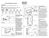
9
Front
Lift Points
Front
Front
Front
Lift Points
Lift Points
Lift Points
Unitized Body
Stub Frame
Perimeter Frame
Pickup Truck
Typical Lift Points
Fig.15
WARNING
Most specialty or modied vehicles can-
not be raised on a frame engaging lift.
Contact vehicle manufacturer for raising
or jacking details.
5. Problems, causes, actions
The following lists contain information on pote-
ntial problems,their causes, and actions to rect-
ify the fault.
Repairs to safety mechanisms on the lift
may richtungen only be carried out by
authorized maintenance contractors
(component persons).
During a breakdown (power failure), the lift
remains automatically in safe mode. This
means that all movement is halted.
If the lift is out of order for long periods,
carry out the following steps:
1. Lower the lift to the lowest position.
2. Switch the main switch to
Off and lock with a padlock.
3. Disconnect the power supply.
5.1 Troubleshooting by the operator
The following troubleshooting measures may
only be carried out by an authorized operator.
Before doing so, make sure that power supply
is connected, the main switch is in the "ON“position.
If thethe problem is not rectied by the listed
measures,you must seek advice from a
competent person.
The troubleshooting measures listed in 5.2
may only be carried out by maintenance
contractors.
i
i
i
i
19

Problem Possible cause Actions
The motor is not running.
• Blown fuse or circuit breaker.
• Overhead Sensor Actuated.
• Up button not functioning.
1. Replace blown fuse or reset circuit
breaker(customer side).
2.Check sensor or incorrect
connection.
3.Check UP button.
4. Contact service representative for
further assistance.
Motor runs but will not raise lift.
•Low oil level.
•Overloading lift.
1. Check and Fill tank.
2.Check vehicle weight and/or
balance vehicle weight on lift.
Lift won't lower. 1. Down button not functioning.
2. Safety Latches won't release.
3. Lowering Valve not
functioning.
Contact service representative for
further assistance.
Lift going up unlevel. See actions Contact service representative for
further assistance.
Anchors will not stay tight. See actions Contact service representative for
further assistance.
Locking latches do not engage. See actions Contact service representative for
further assistance.
Slow lifting speed or oil blowing
out ller breather cap.
See actions Contact service representative for
further assistance.
Lift slowly settles down. See actions Contact service representative for
further assistance.
5.2 Troubleshooting by authorized maintenance contractors
Problem Possible cause Actions
Motor does not run. 1. Blown fuse/circuit breaker.
2. Incorrect voltage to motor.
3. Bad wiring connections.
4. Up switch burned out.
5. Overhead limit switch burned
out.
6. Motor windings burned out.
1. Replace fuse or reset breaker.
2. Supply correct voltage to motor.
3. Repair and insulate all connections.
4. Replace switch/control buttons.
5. Replace overhead limit switch.
6. Replace motor.
20
/