Fujitsu UTP-RX04BH Installation guide

Category
Split-system air conditioners
Type
Installation guide

Fujitsu UTP-RX04BH is a refrigerant branch unit, a part of a VRF system, designed for authorized service personnel only. It requires professional installation and electrical wiring in compliance with local regulations. The unit is not suitable for explosive atmospheres and should be grounded correctly for safety. It does not have user-serviceable parts and should be handled by authorized personnel only.

Fujitsu UTP-RX04BH is a refrigerant branch unit, a part of a VRF system, designed for authorized service personnel only. It requires professional installation and electrical wiring in compliance with local regulations. The unit is not suitable for explosive atmospheres and should be grounded correctly for safety. It does not have user-serviceable parts and should be handled by authorized personnel only.

English
INSTALLATION MANUAL
RB UNIT
For authorized service personnel only.
Deutsch
INSTALLATIONSANLEITUNG
LTEMITTEL-ABZWEIGUNGS-GET
Nur für autorisiertes Fachpersonal.
TM
FrançaisEspañol
MANUEL D’INSTALLATION
MANUAL DE INSTALACIÓN
UNITÉ DE DÉRIVATION DE RÉFRIGÉRANT
UNIDAD DE DERIVACIÓN DE REFRIGERANTE
Pour le personnel agréé uniquement.
Únicamente para personal de servicio autorizado.
Italiano
MANUALE DI INSTALLAZIONE
UNITÀ REFRIGERANTE SECONDARIA
A uso esclusivo del personale tecnico autorizzato.
ΕλληνικάPortuguês
ΕΓΧΕΙΡΙΔΙΟ ΕΓΚΑΤΑΣΤΑΣΗΣ
ΜΟΝΆΔΑ ΔΙΑΚΛΆΔΩΣΗΣ ΨΥΚΤΙΚΟΎ
Μόνο για εξουσιοδοτημένο τεχνικό προσωπικό.
MANUAL DE INSTALAÇÃO
UNIDADE DE DERIVAÇÃO DE REFRIGERANTE
Apenas para técnicos autorizados.
РусскийTürkçe
РУКОВОДСТВО ПО УСТАНОВКЕ
МОДУЛЬ ВЕТКИ ОХЛАЖДЕНИЯ
Только для авторизованного обслуживающего персонала.
MONTAJ KILAVUZU
SOĞUTUCU DAĞITIM ÜNITESI
Yalnızca yetkili servis personeli için.
UTP-RX04BH
PART NO. 9366247043-05
[Original instructions]
En-1
1. SAFETY PRECAUTIONS
Be sure to read this Manual thoroughly before installation.
The warnings and precautions indicated in this Manual contain important informa-
tion pertaining to your safety. Be sure to observe them.
Hand this Manual, together with the Operating Manual, to the customer. Request
the customer to keep them on hand for future use, such as for relocating or repair-
ing the unit.
WARNING
This mark indicates procedures which, if improperly per-
formed, might lead to the death or serious injury of the user.
Never touch electrical components immediately after the power supply has been
turned o . Electrical shock may occur. After turning o the power, always wait 10
minutes or more before touching electrical components.
Request your dealer or a professional installer to install this unit in accordance with
this Installation Manual. An improperly installed unit can cause serious accidents
such as water leakage, electric shock, or re. If this unit is installed in disregard of the
instructions in the Installation Manual, it will void the manufacturer’s warranty.
Do not turn ON the power until all work has been completed. Turning ON the power
before the work is completed can cause serious accidents such as electric shock or
re.
If refrigerant leaks while work is being carried out, ventilate the area. If the refrigerant
comes in contact with a ame, it produces a toxic gas.
Installation work must be performed in accordance with national wiring standards by
authorized personnel only.
During installation, make sure that the refrigerant pipe is attached rmly before you
run the compressor.
Do not operate the compressor under the condition of refrigerant piping not attached
properly with 2-way or 3-way valve open. This may cause abnormal pressure in the
refrigeration cycle that leads to breakage and even injury.
When installing and relocating the air conditioner, do not mix gases other than the
speci ed refrigerant (R410A) to enter the refrigerant cycle.
If air or other gas enters the refrigerant cycle, the pressure inside the cycle will rise to
an abnormally high value and cause breakage, injury, etc.
Be sure to always use the parts accessories or the speci ed parts for installation.
Failure to use the speci ed parts may cause the equipment to fail, water leakage,
electric shock or re.
Install the equipment in a location that is out of reach of children.
Be sure to check that there are no refrigerant leaks after installation is completed.
If there is refrigerant gas leak indoors and comes into contact with an open ame
from such sources as a fan heater, bunsen burner, or stove, it can generate toxic
fumes.
Do not turn OFF the breaker (or the disconnect switch) connected to the RB unit dur-
ing operations except in an emergency. Doing so may cause a compressor malfunc-
tion. When turning OFF the RB unit power, rst stop refrigerant system operations,
and then turn OFF the breaker (or disconnect switch) connected to the RB unit.
CAUTION
This mark indicates procedures which, if improperly per-
formed, might possibly result in personal harm to the user, or
damage to property.
Read carefully all security information before use or install the air conditioner.
Do not attempt to install the air conditioner or a part of the air conditioner by yourself.
This unit must be installed by quali ed personnel with a capacity certi cate for han-
dling refrigerant uids. Refer to regulation and laws in use on installation place.
The installation must be carried out in compliance with regulations in force in the
place of installation and the installation instructions of the manufacturer.
This unit is part of a set constituting an air conditioner. It must not be installed alone
or with non-authorized by the manufacturer.
Always use a separate power supply line protected by a circuit breaker operating on
all wires with a distance between contact of 3mm for this unit.
The unit must be correctly grounded and the supply line must be equipped with a dif-
ferential breaker in order to protect the persons.
The units are not explosion proof and therefore should not be installed in explosive
atmosphere.
Do not turn on the power until all installation work is complete.
This unit contains no user-serviceable parts. Always consult authorized service per-
sonnel to repairs.
When moving, consult authorized service personnel for disconnection and installation
of the unit.
Children should be monitored to ensure they do not play with the device.
This product is not intended to be used by people (including children) with physical,
sensory or mental disability, or persons lacking experience or knowledge unless they
have been given by the through a person responsible for their safety, supervision or
instruction concerning the use of the device.
It is not necessary to provide drainage for this unit.
This equipment is for indoor use only.
2. ABOUT THIS PRODUCT
2.1. Precautions for using R410A refrigerant
WARNING
Do not introduce any substance other than the prescribed refrigerant into the
refrigeration cycle.
If air enters the refrigeration cycle, the pressure in the refrigeration cycle will
become abnormally high and cause the piping to rupture.
If there is a refrigerant leakage, make sure that it does not exceed the concentration limit.
If a refrigerant leakage exceeds the concentration limit, it can lead to accidents
such as oxygen starvation.
Do not touch refrigerant that has leaked from the refrigerant pipe connections or
other area. Touching the refrigerant directly can cause frostbite.
If a refrigerant leakage occurs during operation, immediately vacate the premises
and thoroughly ventilate the area.
If the refrigerant comes in contact with a ame, it produces a toxic gas.
2.2. Special tools for R410A
WARNING
To install a unit that uses the R410A refrigerant, use dedicated tools and piping
materials that have been manufactured speci cally for R410A use.
Because the pressure of the R410A refrigerant is approximately 1.6 times higher
than the R22, failure to use dedicated piping material or improper installation can
cause rupture or injury.
Furthermore, it can cause serious accidents such as water leakage, electric shock,
or re.
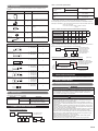
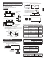
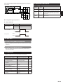
Tool name Contents of change
Gauge manifold
Pressure is huge and cannot be measured with a conventional
(R22) gauge. To prevent erroneous mixing of other refrigerants,
the diameter of each port has been changed.
It is recommended to use a gauge manifold with a high
pressure display range –0.1 to 5.3 MPa and a low pressure
display range –0.1 to 3.8 MPa.
Charging hose
To increase pressure resistance, the hose material and base
size were changed.
Vacuum pump
A conventional (R22) vacuum pump can be used by installing a
vacuum pump adapter. Be sure that the pump oil does not back
flow into the system. Use one capable for vacuum suction of
–100.7 kPa (5 Torr, –755 mmHg).
Gas leakage
detector
Special gas leakage detector for HFC refrigerant R410A.
INSTALLATION MANUAL
PART NO. 9366247043-05
VRF system RB unit
Contents
1. SAFETY PRECAUTIONS .........................................................................................1
2. ABOUT THIS PRODUCT .........................................................................................1
2.1. Precautions for using R410A refrigerant .........................................................1
2.2. Special tools for R410A ..................................................................................1
2.3. Accessories.....................................................................................................2
2.4. Optional parts..................................................................................................2
3. CONNECTION SPECIFICATIONS ...........................................................................2
4.
PIPING SPECIFICATIONS .......................................................................................................2
5. INSTALLATION WORK .............................................................................................2
5.1. Selecting an installation location .....................................................................2
5.2. Installation dimensions....................................................................................3
5.3. Hanger bolt installation ...................................................................................3
5.4. Hanging metal xtures ....................................................................................3
5.5. Installing the hanger........................................................................................3
5.6. Installation of the unit ......................................................................................3
6. PIPE INSTALLATION ................................................................................................4
6.1. Pipe selection..................................................................................................4
6.2. Selecting the pipe material..............................................................................5
6.3. Pipe connection ..............................................................................................5
6.4. Installing heat insulation..................................................................................5
7. ELECTRICAL WIRING ..............................................................................................5
7.1. Safety precautions for electrical wiring ...........................................................5
7.2. Electrical requirement .....................................................................................6
7.3. Wiring ..............................................................................................................6
8. FIELD SETTING ........................................................................................................9
8.1. PC board layout ..............................................................................................9
8.2. Address setting ...............................................................................................9
8.3. Function setting...............................................................................................9
9. EXTERNAL INPUT ....................................................................................................9
10. TEST RUN...............................................................................................................10
10.1. Test run using Outdoor unit (PC board) .......................................................10
10.2. Test run using Remote Controller .................................................................10
11. CHECK LIST ...........................................................................................................10
12. INDICATOR LAMP STATUS ...................................................................................10
En-2
2.3. Accessories
Do not discard the accessories required for installation until the installation work is
complete.
Name and shape Q’ty Application
Installation Manual
1
This manual
Hanger
4
For suspending the RB unit from
ceiling
Washer
8
For suspending the RB unit from
ceiling
Tapping screw
(ø4×10)
8
For suspending the RB unit from
ceiling
Cable tie
5
For mounting the transmission
cable
Reducer type Q'ty
Reducer-A
ab
a: ø9.52 [O.D.]
b: ø12.7 [I.D.]
4
Reducer-B
ab
a: ø9.52 [O.D.]
b: ø6.35 [I.D.]
4
Reducer-C
ab
a: ø19.05 [O.D.]
b: ø22.22 [I.D.]
2
Reducer-D
abс
a: ø19.05 [O.D.]
b: ø12.7 [I.D.]
c: ø15.88 [I.D.]
2
Reducer-E
a
b
с
d
a: ø28.58 [O.D.]
b: ø22.22 [I.D.]
c: ø19.05 [I.D.]
d: ø15.88 [I.D.]
2
Reducer-F
a
b
с
d
a: ø22.22 [O.D.]
b: ø19.05 [I.D.]
c: ø15.88 [I.D.]
d: ø12.7 [I.D.]
2
Reducer-G
a
b
с
a: ø15.88 [O.D.]
b: ø12.7 [I.D.]
c: ø9.52 [I.D.]
2
2.4. Optional parts
The following optional parts are available.
Description Model No. Application
External connect kit
UTY-XWZXZ6
For external input
(Dry contact terminal / CNA01)
UTY-XWZXZB
For external input
(Apply voltage terminal / CNA02)
3. CONNECTION SPECIFICATIONS
O.U.=Outdoor unit
I.U.=Indoor unit
O.U.
I.U. I.U. I.U.
I.U. I.U.
RB unit
Basic connection speci cations
Up to 8 units
Table 1) Connection speci cations
Maximum capacity of
connectable indoor
units (Q)
1 RB unit
Q 56.0kW
2 RB units (in serial) *1
Maximum capacity of connectable indoor units per
branch (Q)
Q 18.0kW
Maximum number of connectable indoor units per
branch
Up to 8 units
*1: Downstream of this unit, you can connect 1 RB unit of the same type.
The total capacity of the indoor units connected downstream is calculated as follows.
Example of calculation: In the case that the model codes of the connected indoor units
are 07, 09, 12 and 18.
Q = 2.2kW + 2.8kW + 3.6kW + 5.6kW = 14.2kW
Good
Table 2) Indoor unit model codes and model selection capacity
Model code 04 07 09 12 14 18 24
Indoor unit
capacity (Kw)
1.1 2.2 2.8 3.6
4.0
4.5
5.6 7.1
Model code 30 34 36 45 54 60
Indoor unit
capacity (Kw)
8.0
9.0
10.0 11.2 12.5 14.0 18.0
For connectable indoor units, refer to the catalogue or the Design & Technical manu-
al.
You must connect the indoor units with 3 or more branches.
I.U. I.U. I.U.
O.U.
RB unit
If connecting indoor
units with 3 branches,
you must connect
indoor units to the
branch furthest from
the outdoor unit.
To outdoor unit
To indoor unit
RB unit
RB unit
* Height:
20 or less
To indoor unit
* The RB unit on the down-
stream side must be installed
at a lower height level than
the upstream RB unit.
Length:
1000 or less
(Unit: mm)
Restrictions on installation related to serial connections
4. PIPING SPECIFICATIONS
For details of piping speci cations, refer to the outdoor unit installation manual.
5. INSTALLATION WORK
5.1. Selecting an installation location
WARNING
Take into consideration whether the place you install the main unit can fully with-
stand its weight.
For hanger bolts, use embedded inserts or embedded foundation bolts in the case
of new installation, and use a hole-in-anchor if already installed, and attach in a
way so that the unit’s weight can be supported.
CAUTION
Do not install this unit in the following areas:
• Area with high salt content, such as at the seaside. It will deteriorate metal parts,
causing the parts to fail or the unit to leak water.
• Area lled with mineral oil or containing a large amount of splashed oil or steam,
such as a kitchen. It will deteriorate plastic parts, causing the parts to fail or the unit
to leak water.
• Area that generates substances that adversely a ect the equipment, such as sulfu-
ric gas, chlorine gas, acid, or alkali. It will cause the copper pipes and brazed joints
to corrode, which can cause refrigerant leakage.
• Area containing equipment that generates electromagnetic interference. It will cause
the control system to malfunction, preventing the unit from operating normally.
• Area that can cause combustible gas to leak, contains suspended carbon bers or
ammable dust, or volatile in ammables such as paint thinner or gasoline. If gas
leaks and settles around the unit, it can cause a re.
• Area where small animals may live. It may cause failure, smoke or re if small
animals enter and touch internal electrical parts.
• Area where animals may urinate on the unit or ammonia may be generated.
En-3
CAUTION
Install this unit, power supply cable and transmission cable at least 1 m away
from a television or radio receivers. The purpose of this is to prevent TV reception
interference or radio noise. (Even if they are installed more than 1 m apart, you
could still receive noise under some signal conditions.)
If children under 10 years old may approach the unit, take preventive measures so
that they cannot reach the unit.
Select the place to instal the product after taking into consideration the following condi-
tions, and after obtaining approval from the customer.
Install this unit in a location that has strong support and no vibrations.
Install in a location that has enough space for this unit installation.
Install in a well-ventilated area.
Install in a location that is not exposed to high temperatures or humidity over a long
periods.
Do not install the unit near a bedroom. Refrigerant noise may be heard from the pip-
ing.
5.2. Installation dimensions
Provide a service access for maintenance and inspection purposes as shown in the
gure below. Be sure to prepare service access in control box side.
It is not necessary to provide drainage for this unit.
Install the RB unit without slant. (within ±2°).
Use M8 or M10 for the hanger bolt size when hanging.
A
E
D
C
B
H
G
F
Suction gas pipe
Liquid pipe
Discharge gas pipe
Liquid pipe
Gas pipe
Discharge
gas pipe
Liquid pipe
Suction gas pipe
UPWARD
5.2.1. Ceiling hanging
Be sure to install so that the top side faces up.
54
150
174
150
150
174
150
80
149
62
264
36
FE
A
158
658
158
18
HG
692
146
363
428
D
CB
(Unit: mm)
(Top side)
Product mass (kg)
UTP-RX04BH 31.5
Left side Right side
155
95
50
40
56
147
260
147
56
40
155
96
50
service access
400 or more
700 or more
Service access
(Unit: mm)
500
or more
500
or more
20 or more
(Unit: mm)
20 or more
Ceiling hanging
Installation limit
5.3. Hanger bolt installation
WARNING
Take into consideration whether the place you install the main unit can fully withstand
its weight, and, if necessary, install a hanger bolt after reinforcing with a beam.
Use a M8 or M10 size hanger bolt.
5.4. Hanging metal xtures
Support the connected piping within 1 m in front of and behind the main unit using
hanging metal xtures. If you place excessive weight on the main units hanging metal
xture, the unit may fall o .
5.5. Installing the hanger
Hanger ×4 (accessories)
Tapping screw ×8
(accessories)
Mount the hanger (accessories).
5.6. Installation of the unit
WARNING
Perform installation in a location which can properly withstand the weight of the unit.
Failure to install in a faulty installment may cause the equipment to fail, water leak-
age, electric shock or re.
During installation, secure the hanger bolt so it does not come o .
En-4
CAUTION
Be sure to provide adequate maintenance space when installing the unit above the
ceiling.
(Refer to the installation restrictions contained in “5.2. Installation dimensions”.)
5.6.1. Removing the pinch pipe
Melt the brazing ller metal on connecting part using a torch
and remove the pinch pipe.
If using the R-side
If using the L-side
Pinch pipe
Pinch pipe
Pinch pipe
Pinch pipe
Pinch pipe
Seal the unused pinch
pipe end by pinch
treating it.
Seal the pinch pipe end
on the unused side by
pinch treating it.
L-side
L-side
R-side
R-side
5.6.2. Fix the unit (When hanging from the ceiling)
(1) Attach the hanger (accessories) to the hanger bolts as shown in the overview
diagram below. (in 4 places)
(2) After checking that the equipment is horizontal, rmly xed in place with the
nuts (locally purchased) and washers (accessories).
Hanger bolt
(8 to 10)
Hexagonal nut
(locally purchased)
Hexagonal nut
(Double nut)
(locally purchased)
Hanger
(accessories)
Washers
(accessories)
30 to 40
(Unit: mm)
6. PIPE INSTALLATION
6.1. Pipe selection
(1) Select the piping to connect to the RB unit.
Type A) If connecting 1 indoor unit downstream of the RB unit
Suction gas pipe
Discharge gas pipe
Liquid pipe
Indoor unit
Liquid pipe
Gas pipe
RB unit
Select the connection pipe from Table 1, based on the total
capacity of indoor units connected downstream.
Select the connection
pipe from Table 3, based
on the capacity of the
indoor unit connected.
To outdoor unit or
other RB unit
Type B)
If connecting 2 or more indoor units downstream of the RB unit
Indoor unit
Indoor unit
Select the connection pipe from Table 1, based on the
total capacity of indoor units connected downstream.
• Select the connection pipe from Table 2, based
on the total capacity of indoor units connected
downstream.
• For piping from branch kit to indoor unit, refer
to the installation manual for the outdoor unit.
Suction gas pipe
Discharge gas pipe
Liquid pipe
RB unit
Liquid pipe
Gas pipe
To outdoor unit or
other RB unit
(2) If the size of the selected pipe is di erent from Table 4, use reducers (accessories)
to make the diameters match.
Connection pipe Reducer
Reducer
RB unit
Table 1) Indoor unit total capacity and RB unit upstream side connection pipe sizes
Total capacity of
indoor unit (kW)
Upstream of RB unit
Suction gas pipe
(mm (in))
Discharge gas
pipe (mm (in))
Liquid pipe
(mm (in))
1.1 to 11.1
ø15.88 (5/8")
+Reducer
ø12.7 (1/2")
+Reducer
ø9.52 (3/8")
+Reducer
11.2 to 13.9
ø19.05 (3/4")
+Reducer
ø12.7 (1/2")
+Reducer
ø9.52 (3/8")
+Reducer
14.0 to 22.3
ø22.22 (7/8")
+Reducer
ø15.88 (5/8")
+Reducer
ø12.7 (1/2")
+Reducer
22.4 to 28.0
ø22.22 (7/8")
+Reducer
ø19.05 (3/4")
+Reducer
ø12.7 (1/2")
+Reducer
28.1 to 44.7 ø28.58 (1-1/8")
ø19.05 (3/4")
+Reducer
ø12.7 (1/2")
+Reducer
44.8 to 46.9 ø28.58 (1-1/8")
ø19.05 (3/4")
+Reducer
ø15.88 (5/8")
47.0 to 56.0 ø28.58 (1-1/8") ø22.22 (7/8") ø15.88 (5/8")
Table 2) Indoor unit total capacity and RB unit downstream side connection
pipe sizes
Total capacity of
indoor unit (kW)
Downstream of RB unit
Gas pipe (mm (in)) Liquid pipe (mm (in))
2.2 to 11.1
ø15.88 (5/8")
+Reducer
ø9.52 (3/8")
11.2 to 13.9 ø19.05 (3/4") ø9.52 (3/8")
14.0 to 18.0
ø22.22 (7/8")
+Reducer
ø12.7 (1/2")
+Reducer
Table 3) Indoor unit capacity and connection pipe sizes
Indoor unit capacity
Downstream of RB unit
Gas pipe (mm (in))
Liquid pipe
(mm (in))
1.1 , 2.2 , 2.8 , 3.6 ,
4.0 , 4.5
ø12.7 (1/2")
+Reducer
ø6.35 (1/4")
+Reducer
5.6 , 7.1 , 8.0 , 9.0, 10.0
ø15.88 (5/8")
+Reducer
ø9.52 (3/8")
11.2 , 12.5 , 14.0 , 18.0 ø19.05 (3/4") ø9.52 (3/8")
Table 4) RB unit pipe size
Outdoor unit side Indoor unit side
Suction gas
pipe (mm (in))
Discharge gas
pipe (mm (in))
Liquid pipe
(mm (in))
Gas pipe
(mm (in))
Liquid pipe
(mm (in))
ø28.58 (1-1/8")
ø22.22 (7/8") ø15.88 (5/8") ø19.05 (3/4") ø9.52 (3/8")
En-5
(3) Indoor unit model codes and model selection capacity
Model code 04 07 09 12 14 18 24
Indoor unit
capacity (Kw)
1.1 2.2 2.8 3.6
4.0
4.5
5.6 7.1
Model code 30 34 36 45 54 60
Indoor unit
capacity (Kw)
8.0
9.0
10.0 11.2 12.5 14.0 18.0
6.2. Selecting the pipe material
Copper pipes
It is necessary to use seamless copper pipes and it is desirable that the amount of
residual oil is less than 40 mg/10 m. Do not use copper pipes having a collapsed, de-
formed or discolored portion (especially on the interior surface). Otherwise, the expan-
sion valve or capillary tube may become blocked with contaminants.
As an air conditioner using R410A incurs pressure higher than when using conventional
refrigerant (R22), it is necessary to choose adequate materials.
Thicknesses of copper pipes used with R410A are as shown in the table. Never use
copper pipes thinner than that in the table even when it is available on the market.
Thicknesses of Annealed Copper Pipes (R410A)
Pipe outside diam-
eter [mm (in)]
Thickness
[mm] *1
Material
6.35 (1/4") 0.80
COPPER JIS H3300
C1220T-O or equivalent
(Allowable tensile
stress 33 (N/mm
2
))
9.52 (3/8") 0.80
12.70 (1/2") 0.80
15.88 (5/8") 1.00
19.05 (3/4") 1.20
22.22 (7/8") 1.00
COPPER JIS H3300
C1220T-H or equivalent
(Allowable tensile
stress 61 (N/mm
2
))
28.58 (1-1/8") 1.00
*1 Endurance pressure of the pipes 4.2MPa
6.3. Pipe connection
6.3.1. Brazing
CAUTION
If air or di erent type of refrigerant enters the refrigeration cycle, the internal pres-
sure in the refrigeration cycle will become abnormally high and prevent the unit
from exerting its full performance.
Apply nitrogen gas while brazing the pipes.
Nitrogen gas pressure: 0.02 MPa
(= su cient pressure to be felt on
Pressure regulating valve
Brazing area
Nitrogen gas
Cap
the back of your hand or more)
If a pipe is brazed without applying nitrogen gas, it will create an oxidation lm.
This can degrade performance or damage the parts in the unit (such as the com-
pressor or valves).
Do not use ux to braze pipes. If the ux is the chlorine type, it will cause the pipes
to corrode.
In addition, if the ux contains uoride, it will a ect the refrigerant piping system due to
deterioration of refrigerant oil.
For brazing material, use phosphor copper that does not require ux.
6.3.2. Bending pipes
The pipes are shaped by your hands. Be careful not to collapse them. Do not bend the
pipes in an angle more than 90°.
When pipes are repeatedly bent or stretched, the material will harden, making it di cult
to bend or stretch them any more. Do not bend or stretch the pipes more than 3 times.
CAUTION
To prevent breaking of the pipe, avoid sharp bends. Bend the pipe with a radius of
curvature of 100 mm or over.
If the pipe is bent repeatedly at the same place, it will break.
6.3.3. Pipe connection
Liquid pipe
Discharge gas pipe
Suction gas pipe
Gas pipe
Liquid pipe
The pipe can be connected by brazing
Brazing
Brazing
RB
unit
6.4. Installing heat insulation
CAUTION
Insulate the suction gas pipe, discharge gas pipe, liquid pipe, and gas pipe with heat
insulation.
Use heat insulation with heat resistance above 120 °C.
In addition, if the humidity level at the installation location of the refrigerant piping is
expected to exceed 70%, install heat insulation around the refrigerant piping. If the
expected humidity level is 70-80%, use heat insulation that is 15 mm or thicker and if
the expected humidity exceeds 80%, use heat insulation that is 20 mm or thicker.
If heat insulation is used that is not as thick as speci ed, condensation may form
on the surface of the insulation. In addition, at 20 °C, use heat insulation with heat
conductivity of 0.045 W/(m·K) or less.
6.4.1. Piping insulation
(1) After the sealing test is complete, carry out insulation work.
(2) Insulate all pipes and piping connection parts so that there is no gap in it.
(3) Firmly connect the terminal part (a) so that no air comes in or out.
(4) Do not squeeze the cable ties excessively so as to ensure that the insulation mate-
rial is thick.
(a)
Insulation (locally purchased)
Cable tie (locally purchased)
RB Unit
7. ELECTRICAL WIRING
7.1. Safety precautions for electrical wiring
WARNING
Electrical work must be performed in accordance with this Manual by a person
certi ed under the national or regional regulations. Be sure to use a dedicated circuit
for the unit.
An insufficient power supply circuit or improperly performed electrical work can
cause serious accidents such as electric shock or re.
Before starting work, check that power is not being supplied to the RB unit, indoor
unit and outdoor unit.
For wiring, use the prescribed type of cables, connect them securely, making sure
that there are no external forces of the cables applied to the terminal connections.
Improperly connected or secured cables can cause serious accidents such as
overheating the terminals, electric shock, or re.
Securely install the electrical box cover on the unit.
An improperly installed electrical box cover can cause serious accidents such as
electric shock or re through exposure to dust or water.
Use the included connection cables and power cables or ones specified by the
manufacturer. Improper connections, insufficient insulation, or exceeding the
allowable current can cause electric shock or re.
Do not modify the power cables, use extension cables, or use any branches in the
wiring. Improper connections, insufficient insulation, or exceeding the allowable
current can cause electric shock or re.
Match the terminal block numbers and connection cable colors with those of the
indoor unit or outdoor unit. Erroneous wiring may cause burning of the electric parts.
Securely connect the connection cables to the terminal board. In addition, secure
the cables with wiring holders. Improper connections, either in the wiring or at the
ends of the wiring, can cause a malfunction, electric shock, or re.
Always fasten the outside covering of the connection cable with the cable clamp. (If
the insulator is chafed, electric discharge may occur.)
Install an earth leakage breaker. In addition, install the earth leakage breaker so
that the entire AC main power supply is cut o at the same time. Otherwise, electric
shock or re could result.
Always connect the earth (ground) cable.
Improper earthing (grounding) work can cause electric shocks.
Perform wiring work in accordance with standards so that the air conditioner can be
operated safely and positively.
If the supply cable is damaged, it must be replaced by the manufacturer, its service
agent or similarly quali ed persons in order to avoid a hazard.
CAUTION
Earth (Ground) the unit.
Do not connect the earth (ground) cable to a gas pipe, water pipe, lightning rod, or
a telephone earth (ground) cable.
Improper earthing (grounding) may cause electric shock.
En-6
Do not connect power supply cables to the transmission terminals, as this will
damage the product.
Never bundle the power supply cable and transmission cable, together.
Separate these cable by 50 mm or more.
Bundling these cables together will cause miss operation or breakdown.
When handling PC board, static electricity charged in the body may cause
malfunction of the PC board. Follow the cautions below:
Establish an earth (ground) for the RB units , indoor units, outdoor units and
peripheral devices.
• Cut power (breaker) o .
Touch metal part of the RB units, indoor units and outdoor units for more than
10 seconds to discharge static electricity charged in the body.
• Do not touch terminals of parts and patterns implemented on PC board.
7.2. Electrical requirement
Voltage rating 230 V
Operating range 198 to 264 V
• Select the power cable type and size in accordance with relevant local and national
regulations.
• Speci cations for local wiring power cord and branch wiring are in compliance with
local code.
• Max. wire length: Set a length so that the voltage drop is less than 2%. Increase the
wire diameter when the wire length is long.
Breaker should be installed at every refrigerant system. Do not use a breaker in a
di erent refrigerant system.
Refer to the table for the breaker speci cations of each installation condition. Perform
the power crossover wiring within the range of the same refrigerant system. When the
crossover wiring is done, make a connection for RB units to satisfy conditions A and B
below.
A. Current breaker requirements
Model MCA MFA
UTP-RX04BH 0.76 A 20 A
MCA: Minimum Circuit Ampacity
MFA: Maximum Fuse Ampacity
When the power crossover wiring is done, make it so that the total of the MCA of the
connected RB units and indoor units does not exceed the 15 A. For indoor unit MCA,
refer to the indoor unit installation manual.
If the capacity of connected RB units and indoor units exceeds the upper limit, either
add breakers or use a breaker with a greater capacity.
B. Earth leakage breaker requirements
Breaker capacity Connectable RB units and indoor units
30 mA, 0.1 sec or less 44 or less *
100 mA, 0.1 sec or less 45 to 148
* If the total number of units connected to the breaker exceeds 44, either add a 30mA
breaker, or use breakers with a greater capacity.
7.2.1. Cable speci cations
Follow the speci cations below for the power supply and transmission cable.
Recommended
cable size
(mm
2
)
Cable type Remark
Power supply
cable
2.5
Type60245
IEC57 or
equivalent
1ø 50 Hz 198 to 264 V
2 Cable + earth (ground)
Transmission
cable
0.33
LONWORKS
compatible
cable
22 AWG LEVEL 4
(NEMA) non-polar 2
core, twisted pair solid
core diameter 0.65 mm
7.3. Wiring
7.3.1. Power supply cable
Keep the ground cable longer than the other cables.
20 mm
Power supply cable
30 mm
Earth (Ground)
cable
(1) Use ring terminals with insulating sleeves as shown in the gure below to connect
to the terminal block.
(2) Securely clamp the ring terminals to the cables using an appropriate tool so that the
cables do not come loose.
(3) Use the speci ed cables, connect them securely, and fasten them so that there is
no stress placed on the terminals.
(4) Use an appropriate screwdriver to tighten the terminal screws.
Do not use a screwdriver that is too small, otherwise, the screw heads may be
damaged and prevent the screws from being properly tightened.
(5) Do not tighten the terminal screws too much, otherwise, the screws may break.
(6) See the table for the terminal screw tightening torques.
(7) Please do not x 2 power supply cables with 1 screw.
Strip 10 mm
Sleeve
Screw with spe-
cial washer
Screw with
special washer
Ring terminal
Cable
Cable
Terminal block
Ring terminal
Ring
terminal
WARNING
Use ring terminals and tighten the terminal screws to the specified torques,
otherwise, abnormal overheating may be produced and possibly cause heavy
damage inside the unit.
Tightening torque
M4 screw
(Power supply / L, N, GND)
1.2 to 1.8 N·m
(12 to 18 kgf·cm)
7.3.2. Transmission cable
30 mm
40 mm
Shielded cable
(no lm)
GOOD PROHIBITED
Di erent diameter
Connect to 1 side
WARNING
Tighten the terminal screws to the specified torques, otherwise, abnormal
overheating may be produced and possibly cause heavy damage inside the unit.
Tightening torque
M3 screw
(Transmission / X1, X2)
0.5 to 0.6 N·m
(5 to 6 kgf·cm)
CAUTION
To peel the lm from the lead cable, use a dedicated tool that will not damage the
conductor cable.
When installing a screw on the terminal block, do not cut the cable by
overtightening the screw. On the other hand, an under tightened screw can cause
faulty contact, which will lead to a communication failure.
En-7
7.3.3 Wiring method
The wiring example for RB units ,outdoor units and indoor units is shown in the gure.
LN
LN
LN
LN
LN
LN
*1
Breaker Breaker
Breaker
Power supply
230V 1
50Hz
Power
supply
Power
supply
Power
supply
Outdoor unit
Transmission
Transmission Transmission Transmission Transmission
Transmission
Transmission
Transmission
Indoor unit
Power supply
230V 1
50Hz
Power supply
230V 1 50Hz
RB unit RB unit
RB unit
[UTP-RX01*H]
Indoor unit Indoor unit Indoor unit Indoor unit
Indoor unit
Indoor unit
Refrigerant piping
*1:Cooling only
LN
LN
Breaker
Power supply
230V 1
50Hz
Power
supply
Transmission Transmission Transmission
Transmission Transmission
RB unit
Indoor unit Indoor unit Indoor unit
Indoor unit Indoor unit
The transmission cable connects indoor units belonging to the same RB group. The transmission cable cannot
be used to connect indoor units belonging to di erent RB groups.
GOOD PROHIBITED PROHIBITED
Refrigerant pipe
RB unit RB unit RB unit
Refrigerant pipe
RB group RB group RB group
Transmission line
Transmission line
Transmission line
L
N
L
N
L
N
L
N
Crossover wiring of power supply
RB unit
: Pull box
RB unitRB unit
Breaker
Power supply
230V 1ø 50Hz
Power supply
Power supply
Power supply
RB unit RB unit
GOOD
PROHIBITED
Transmission line
RB group RB group
Refrigerant pipe Refrigerant pipe
If using the indoor unit as a dedicated room cooling device, connect the
transmission terminal of the indoor unit to the "OUT/RB" terminal of RB unit or
outdoor unit transmission terminal.
En-8
7.3.4. Work procedure
(1) Remove the control box cover. (3 screws)
(2) Connect the transmission cable to the transmission cable terminal.
(3) Firmly attach the transmission cables using the accessory cable ties. (Up to 5 loca-
tions)
(4) Connect the power supply cable to the power supply cable terminal.
(5) Firmly x the power supply cable clamp in place.
Top view
A
B
C
(2) Transmission cable
To outdoor unit / other RB unit /
indoor unit (Cooling only)
(2) Transmission cable
to indoor unit
PC board
PC board
PC board
PC board
(2) Transmission cable
to indoor unit
(2) Transmission cable
to indoor unit
(2) Transmission cable
to indoor unit
[INDOOR UNIT D]
[INDOOR UNIT C]
[INDOOR UNIT B]
[INDOOR UNIT A]
(3)
(3)
(3)
(3)
(3)
(5)
(6)
(6)
(6)
(6)
(6)
(6)
(4) Power supply cable
Earth (ground)
Earth (ground)
To outdoor unit / other
RB unit / indoor unit
(Cooling only)
To indoor unit
(cooling / heating)
(Do not use)
TRANSMISSION
TO OUTDOOR UNIT
OR RB UNIT
Detail A : Power supply cable
Detail B : Transmission cable
Detail C : Transmission cable
(6) Fill the cable holes with putty in order to prevent small animals from entering.
(7) Install the Control box cover. (3 screws)
En-9
9. EXTERNAL INPUT
RB unit can be switched cooling priority and heating priority by using RB
unit PC board CNA01 or CNA02.
The "external input priority mode" must be set by changing DIP switch
SET2-1,2 on PC board of RB unit.
A twisted pair cable (22AWG) should be used. Maximum length of cable is
150m.
Use an external input cable with appropriate external dimension, depending
on the number of cables to be installed.
The wire connection should be separate from the power cable line.
INPUT SELECT
Use either one of these types of terminal according to the application. (Both types of
terminals cannot be used simultaneously.)
Dry contact terminal ([CNA01])
When a power supply is unnecessary at the input device you want to connect, use
the Dry contact terminal ([CNA01]).
*a: Select very low current use
contacts (usable at DC12V,
DC1mA or less).
*b: The wiring is di erent from
Apply voltage terminals. Be
su ciently careful when wiring.
1
2
connected unit
PC Board
GND
*a
*b
CNA01
When connected to Dry contact terminals of multiple RB units with a connected unit,
insulate each RB unit with relay, etc. as shown on below example.
RB unitRB unit
Power supply for relay
Input device
K1-K2 : Relay
(Device for DC current)
PC board
PC board
K1
K2
CNA 01
CNA 01
NOTE : When connected to multiple RB units directly, it will cause breakdown.
Apply voltage terminal ([CNA02])
When a power supply must be provided at the input device you want to connect, use
the Apply voltage terminal ([CNA02])
1
2
3
+
+
-
-
Input device
Load
resistance
*1
DC power sup-
ply 12 - 24V
connected unit
PC board
CNA02
*c
*d
*1: Make the power supply DC12 to 24V. Select a power supply capacity with an
ample surplus for the connected load.
Do not impress a voltage exceeding 24V across pins 1-3.
*c: T
he allowable current is DC 5mA to 10mA. (Recommended: DC5mA)
Provide a load resistance such that the current becomes DC10mA or less.
Select very low current use contacts (usable at DC12V, DC1mA or less).
*d: The polarity is [+] for pin 1 and [-] for pin 3. Connect correctly.
8. FIELD SETTING
CAUTION
Use an insulated screwdriver to set the dip switches.
8.1. PC board layout
• Before turning ON the power supply, set the switches. (The switch settings will be
disabled after the power supply has been turned ON.)
PC board
DIP switch
SET1
DIP switch SET1
(setting disabled)
Rotary switch
External Input
connector
Error indicator
lamp (Red)
Power indicator
lamp (Green)
CNA01
CNA02
DIP switch SET2
Rotary switch
DIP switch
SET2
8.2. Address setting
(1) RB unit address
When connecting multiple RB units to 1 refrigerant system, set the address at RB
AD SW.
Rotary switch (RB AD × 1)...Factory setting “0”
Rotary switch (RB AD × 10)...Factory setting “0”
(2) Refrigerant circuit address
In the case of multiple refrigerant systems, set REF AD SW
for each refrigerant system. Set to the same refrigerant circuit address as the
outdoor unit.
Rotary switch (REF AD × 1)...Factory setting “0”
Rotary switch (REF AD × 10)...Factory setting “0”
Setting Type of switch Setting range
RB unit address
Manual address setting
Setting
example
“2”
RB AD × 10 RB AD × 1
Automatic address setting*
Set this switch to 00 at factory setting.
0 to 63
Refrigerant
circuit address
Manual address setting
Setting
example
“63”
REF AD × 10 REF AD × 1
Automatic address setting*
Set this switch to 00 at factory setting.
0 to 99
* For details of automatic address setting, please refer to the outdoor unit installation
manual.
8.3. Function setting
Set the DIP switch SET2, referring to the table.
(1) Operation mode selecting switch
SET 2
Operation mode Remarks
12
OFF OFF Priority given to the rst command Factory setting
ON OFF
Priority given to external input of RB
unit
OFF ON
Priority given to administrative
indoor unit
ON ON Setting forbidden
(2) Cool/heat selection control time
SET 2
Cool/heat selection control time Remarks
34
OFF OFF 6 min Factory setting
ON OFF 3 min
OFF ON Setting forbidden
ON ON
Setting forbidden
If the cool/heat selection control time is short, the sound of passing refrigerant may
be loud during the cool/heat selection control process.
Settings other than those in specified positions are not to be changed.
En-10
When connected to Apply voltage terminals of multiple RB units with a connected
unit, be sure to make a branch outside the RB unit using a pull box, etc. as shown on
below example.
Input device
RB unitRB unit
Load
resistance
DC power sup-
ply 12 - 24V
connected unit
PC board
PC board
CNA
02
CNA
02
Cooling/heating priority function
"Edge" input only
Connector Input signal Command
CNA01 or CNA02
OFF ON Heating priority
ON OFF Cooling priority
CNA01 or CNA02
Priority mode
Heating
On
O
Cooling
10. TEST RUN
10.1. Test run using Outdoor unit (PC board)
• Refer to the Installation Manual for the outdoor unit to perform the test run using the
outdoor unit.
10.2. Test run using Remote Controller
• Refer to the Installation Manual for the remote controller to perform the test run
using the remote controller.
11. CHECK LIST
Pay special attention to the check items below when installing the RB unit(s). After
installation is complete, be sure to check the following check items again.
CHECK ITEMS If not performed correctly
CHECK
BOX
Has the RB unit been installed
correctly?
Vibration, noise, RB unit may
drop
Has there been a check for gas
leaks (refrigerant pipes)?
No cooling, No heating
Has heat insulation work been
completed?
Water leakage
Is the voltage of the power source
the same as that indicated on the
label on the RB unit?
No operation, heat or burn
damage
Is the address setting correctly
configured?
No operation
Are the wires and pipes all
connected completely?
No operation, heat or burn
damage
Is the RB unit earthed (grounded)? Short circuit
Is the connection cable the specified
thickness?
No operation, heat or burn
damage
12. INDICATOR LAMP STATUS
Power indi-
cator lamp
(Green)
Error
indicator lamp
(Red)
Status contents
(Lit)
Lit when the power is turned on.
(Lit) (Lit)
The wiring is incorrect. The "IN/U" terminal of RB
unit and outdoor unit transmission terminal are
connected with the transmission cable. Correctly
connect the wiring. When re-wiring, you must turn
o the power.
(Lit)
(Flashing)
There is a fault with the communication board or
the main board.
: 0.1s ON / 0.1s OFF
  • Page 1 1
  • Page 2 2
  • Page 3 3
  • Page 4 4
  • Page 5 5
  • Page 6 6
  • Page 7 7
  • Page 8 8
  • Page 9 9
  • Page 10 10
  • Page 11 11

Fujitsu UTP-RX04BH Installation guide

Category
Split-system air conditioners
Type
Installation guide

Fujitsu UTP-RX04BH is a refrigerant branch unit, a part of a VRF system, designed for authorized service personnel only. It requires professional installation and electrical wiring in compliance with local regulations. The unit is not suitable for explosive atmospheres and should be grounded correctly for safety. It does not have user-serviceable parts and should be handled by authorized personnel only.

Ask a question and I''ll find the answer in the document

Finding information in a document is now easier with AI