
NIM system
INSTALLATION MANUAL
APPENDIX
MOUNTING CONNECTIONGETTING STARTED
SETUP AFTER
INSTALLATION
Thank you for selecting Aiphone for your communication needs. Please read this manual carefully before installation, and keep it
in a safe place for future reference.
Please note that images and illustrations depicted in this manual may differ from the actual product.
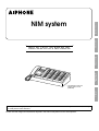
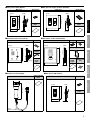
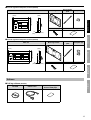
The illustration shows the *
Master station, 40-call
(NIM-40B).

2
Contents
Introduction ................................ 3
Precautions ................................. 3
WARNING ........................................... 3
CAUTION ............................................ 3
GENERAL PRECAUTIONS ............... 3
NOTICES ............................................ 4
System requirements for PC ............ 5
GETTING STARTED ....................... 6
System confi guration ................ 6
Package contents and
dimensions ................................. 8
Master station .................................... 8
Sub station, call button, wall jack ... 8
Ceiling speaker,
ceiling microphone ..........................11
Corridor light, reset button .............11
Software ........................................... 13
MOUNTING .................................. 14
CONNECTION ............................... 18
Connection wiring diagram
(outline) ..................................... 18
Handling cables ........................ 20
Notes about handling cables ......... 20
Connection wiring diagram
(details) ..................................... 21
Connecting to the master station .. 21
Multiple-user room examples of
using the ceiling speaker (NI-LB)
and the ceiling microphone
(NI-SB) .............................................. 22
Multiple-user room examples of
using the ceiling speaker (NI-LB)
and not using the ceiling
microphone (NI-SB) ........................ 23
Multiple-user room examples of
using the bedside handheld sub
stations (NI-RC) etc. ........................ 24
Examples of using the bathroom
call buttons
(NIR-7W or NIR-7HW) ...................... 26
Single room examples of using
the surface mount sub station
(NI-BA) .............................................. 27
Examples of using the fl ush
mount sub station (NI-JA) .............. 28
Notes about connecting to
a corridor light with nameplate
(NIR-31, NIR-32, NIR-34) ................. 29
SETUP AFTER INSTALLATION ... 30
Adjusting volume and
ringtone settings ...................... 30
APPENDIX ..................................... 31
Troubleshooting ....................... 31
Warranty ..................... Back cover

3
Precautions
Prohibited
Do not dismantle unit
Keep unit away from water
Be sure to follow the instruction
WARNING
Negligence could result in death or serious injury.
1. Do not dismantle or alter the unit. Fire or electric shock could
result.
2. Keep the unit away from water or any other liquid.
Fire or electric shock could result.
3. High voltage is present internally. Do not open the case.
Electric shock could result.
4. For power supply, use Aiphone power supply model specifi ed
for use with system. If non-specifi ed product is used, fi re or
malfunction could result.
5. Do not connect any non-specifi ed power source to the +, -
terminals. Also, do not install two power supplies in parallel to a
single input. Fire or damage to the unit could result.
6. Do not connect any terminal on the unit to an AC power line.
Fire or electric shock could result.
7. Keep AC cord from being marred or crushed. If the AC cord is
damaged, fi re or electric shock could result.
8.
Do not plug or unplug unit with wet hands. Electric shock could
result.
9. Insert AC plug completely and securely into AC outlet.
Otherwise, fi re or electric shock could result.
10.
Periodically check for and remove dust on the power plug. If
dust is left, it could cause the power plug to heat up, resulting in
fi re.
11.
Do not put any metal or fl ammable material into the unit through
the openings. Fire, electric shock, or unit trouble could result.
CAUTION
Negligence could result in injury to people or damage to property.
1.
Do not install or make any wire terminations while power supply
is plugged in. It can cause electrical shock or damage to the unit.
2. When mounting the unit on a wall, install the unit in a
convenient location, but not where it could be jarred or
bumped. Injury could result.
3. Before turning on power, make sure wires are not crossed or
shorted. If not, fi re or electric shock could result.
4.
Do not place or install the unit in the locations subject to frequent
vibration or impact. If the unit falls, injury to people or damage to
the unit could result.
5. Do not put anything on the unit or cover the unit with cloth, etc.
Fire or unit trouble could result.
6. Do not install the unit in any of the following locations. Fire,
electric shock, or unit trouble could result.
Places under direct sunlight or near heating equipment that *
varies in temperature.
Places subject to dust, oil, chemicals, hydrogen sulfi de (hot *
spring).
Places subject to moisture and humidity extremes, such as *
bathrooms, cellars, greenhouses, etc.
Places where the temperature is quite low, such as inside a *
refrigerated area or in front of an air conditioner.
Places subject to steam or smoke (near heating or cooking *
surfaces).
Where noise generating devices such as dimmer switches or *
inverter electrical appliances are closeby.
Locations subject to frequent vibration or impact.*
Locations subject to extremely powerful electric fi elds.*
7. Be sure to perform a call test or check the chime volume with
the handset on the hook. If you operate the hook switch with
the handset on your ear, a sudden call etc. may cause damage
to your ear.
8. The unit must be installed and wired by a qualifi ed technician.
GENERAL PRECAUTIONS
1. Keep the unit more than 1 m (3.3') away from radio or TV sets.
2. Keep the intercom wires more than 30cm (12'') away from AC
100-240V wiring. AC induced noise and/or unit malfunction could
result.
3. Comply with all third party manufacturing specifi cations that will be
used with this system.
4. If it is used close to a cellular phone, the unit may malfunction.
5. The unit can be damaged if dropped. Handle with care.
6. The unit will not work during power failure.
7. In areas where broadcasting station antennas are close by, the
intercom system may be affected by radio frequency interference.
8. All the units, except for Sub station, fl ush mount (NI-JA), are
designed for indoor use only. Do not use at outdoor locations.
9. Environmental sound around the unit may hinder clear
communication, but this is not a malfunction.
10. Using a mobile phone or professional-use radio equipment such
as walkie-talkie close to the system may cause a malfunction.
Introduction
The NIM system is a communication system designed for applications in facilities such as hospitals, offi ce buildings, factories,
•
schools, and prisons. Various types of equipment enable you to confi gure a system that meets your needs for not only general
purpose internal communications, but also for calling and communication in health care or various commercial applications. This
system also allows you to check the call history by connecting a PC installed with the specifi ed application software.
The NIM system is telecommunication equipment, not to be used as Medical Equipment.
•

4
NOTICES
We will under no conditions be liable for damage that occurs due
•
to the inability to communicate due to malfunctions, problems, or
operational errors in this product.
We will under no conditions be liable for any damages or losses
•
resulting from this product's contents or specifi cations.
This manual was created by Aiphone Co., Ltd., all rights reserved.
•
Copying a part of or this entire manual without prior permission from
Aiphone Co., Ltd. is strictly forbidden.
Please note that images and illustrations depicted in this manual
•
may differ from the actual ones.
Please note that product specifi cations may be changed for the sake
•
of improvement without prior notice.
This system is not intended for life support or crime prevention. It is
•
just a supplementary means of conveying information. Aiphone will
under no conditions be liable for loss of life or property which occurs
while the system is being operated.

5
System requirements for PC
Your PC must meet the following system requirements to use the NI-SOFT.
Also refer to the instruction manual supplied with your PC.
OS
(English ver. only)
Windows 7 Home Premium/Professional/Ultimate (Service Pack 1, 32/64bit)
Windows 8.1/Pro (32/64bit)
Processor 2.7 GHz or higher
System memory
(RAM)
2 GB RAM or higher
Hard disk Total 100 MB or higher (*1)
Run-time Microsoft® .NET Framework 4.5 (*2)
Display 1024 (W) x 768 (H) or higher, 16-bit or more
Serial port RS-232C, D-sub 9-pin
Fonts Arial
(*1): If the software is to be installed onto a drive other than C: drive, both the C: drive and the installation drive each require 50
MB or more of memory.
(*2): If the specifi ed Run-time is not installed on the PC, it will be installed automatically when installing the NI-SOFT.
The NI-SOFT may not run, or may not operate correctly (such as freezes occurring) on a PC with specifi cations below
•
the necessary requirements.
We recommend using a PC and CD-ROM/DVD-ROM drive that exceed the basic system requirements.
•
The PC should be operable 24 hours a day.
•
Refer to the NI-SOFT operation manual included in the CD-ROM of the NI-SOFT for the setting method of the NI-SOFT.
•
Microsoft and Windows are either registered trademarks or trademarks of Microsoft Corporation in the United States and/or other
countries.

6
GETTING STARTED
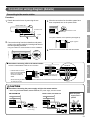
System confi guration
The following is a system confi guration example. You can select needed equipment to confi gure a system to meet your application
needs.
or
CALL
NOTE:
The above example may differ from actual product.
Master station, 40-call (NIM-40B)
Call extension
speaker (IER-2)
Power supply unit
(IS-PU only)
PC for call
log software
(NI-SOFT)
Corridor
light,
single
bed
(NIR-4)
NIR-4
Call
reset
button
(NIR-2)
NIR-2
Ceiling speaker
(NI-LB)
NI-LB
Ceiling
microphone
(NI-SB)
NIR-6
NIR-MB
NIR-MB
NIR-6
NIR-8
NIR-8
NIR-8
Call button
(NIR-6)
Wall jack with
microphone for
NIR-8 (NIR-MB)
Sub station,
fl ush mount
(NI-JA)
Wall jack
for
NI-RC
(NIR-HP)
Bedside handheld
sub station (NI-RC)
NI-RC
Corridor light with
nameplates, 4 names
(NIR-34)
NIR-7W or
NIR-7HW
Wall jack with
hanger for
NI-RC
(NIR-HPF)
Call latching
wall jack for
NIR-8
(NIR-7BS)
NIR-4
NIR-2
(
*
)
: Special order product.
N/A in North America.
• Master station,
20-call (NIM-20B)
• Master station,
60-call
(
*
)
/80-call
(
*
)
Speaker etc. (3W/20Ω,
third party product)
SP-20N/A
(
*
)
(
*
)
: North America only
Bedside call
switch (NIR-8)

7
MOUNTING CONNECTIONGETTING STARTED APPENDIX
SETUP AFTER
INSTALLATION
CALL
CALL
■
Maximum number of stations in a single system
The maximum number of sub stations differs depending on the master station model.
Master station
Sub station (Qty) Personal computer (Qty)
Model Qty
NIM-20B 120 1
NIM-40B 140 1
Master station, 60-call
(
*
)
160 1
Master station, 80-call
(
*
)
180 1
(
*
)
: Special order product.
N/A in North America.
■
Communication methods
The following two methods are available on the master station.
Method Communication style Description
Using handset Voice-actuated communication The communication mode is VOX, half duplex. When speaking
into the handset, voice is transmitted to the other station. When
listening, the voice from the remote station is heard through the
handset.
Hands-free Push-to-talk
To speak, press and hold the
TALK
button.
To listen, release the
TALK
button.
Bathroom
call button
(NIR-7W)
Bathroom
call button
with pull cord
(NIR-7HW)
Sub station,
surface mount
(NI-BA)
NIR-8
NIR-HP
NI-RC
NIR-4
NIR-2
NIR-4
NIR-2
Wall jack
for NIR-8
(NIR-1)
Corridor light
with reset button
(NIR-42)

8
Package contents and dimensions
Verify that the following parts are included for each product package.
Dimensions are shown in millimeters (inches).
*
Master station
■
Master station, 20-call (NIM-20B)
■
Master station, 40-call (NIM-40B)
* Master station, 60-call
(
*
)
or Master station, 80-call
(
*
)
is also available.
Main unit
NIM-20B (Front) NIM-40B (Front) (Side)
480 (18-7/8”)
230 (9-1/16”)
140 (5-1/2”)
330 (13”)
230
(9
-
1/16”)
Room number plate Nameplate
Installation manual/
Operation manual
Chinese RoHS
paper
Sub station, call button, wall jack
■
Bedside handheld sub station (NI-RC)
Main unit Hanging bracket
171.5 (6-3/4”)
95 (3-3/4”)
28 (1-1/8”)
56 (2-3/16”)
ø36 (1-7/16”)
81 (3-3/16”)
19 (3/4”)
Approx. 30 (1-3/16”)
Chinese RoHS paper
NIM-20B: 2pcs.
NIM-40B: 4pcs.
Master station, 60-call: 6pcs.
Master station, 80-call: 8pcs.
NIM-20B: 22pcs.
NIM-40B: 44pcs.
Master station, 60-call: 66pcs.
Master station, 80-call: 88pcs.
(Front)
(Front)
(Side)
Cord: Approx. 1.4m (4.6') Cord: Approx. 1.5m (5')
(Side)
(
*
)
: Special order product.
N/A in North America.

9
MOUNTING CONNECTIONGETTING STARTED APPENDIX
SETUP AFTER
INSTALLATION
■
Wall jack for NI-RC (NIR-HP)
■
Wall jack with hanger for NI-RC (NIR-HPF)
Main unit Screw (x2) Main unit Screw (x4)
120 (4-3/4”)
12 (1/2”)70 (2-3/4”)
120 (4-3/4”)
23 (7/8”)
116 (4-9/16”)
Chinese RoHS
paper
Chinese RoHS
paper
■
Sub station, fl ush mount (NI-JA)
■
Sub station, surface mount (NI-BA)
Main unit Screw (x4) Main unit Screw (x2)
Wood screw (x2)
120 (4-3/4”)
120 (4-3/4”)
2 (1/16”)
150 (5-7/8”)
130 (5-1/8”)
33 (1-5/16”)
Mounting bracket
Hexagonal
wrench
Chinese
RoHS
paper
Chinese
RoHS
paper
Rubber foot
(x4)
■
Bedside call switch (NIR-8)
■
Wall jack for NIR-8 (NIR-1)
Main unit
Chinese RoHS
paper
Main unit Screw (x2)
95 (3-3/4”)
ø36 (1-7/16”)
120 (4-3/4”)
12 (1/2”)
70 (2-3/4”)
Chinese RoHS
paper
(Front)
(Side)
(Front)
(Side)
(Front)
(Front)
(Side)
(Side)
(Front)
(Side)
Cord:
Approx.1.4m (4.6')

10
■
Wall jack with microphone for NIR-8 (NIR-MB)
■
Call latching wall jack for NIR-8 (NIR-7BS)
Main unit Screw (x2) Main unit Screw (x2)
120 (4-3/4”)
12 (1/2”)
70 (2-3/4”)
120 (4-3/4”)
70 (2-3/4”)
12 (1/2”)
Chinese RoHS
paper
Chinese RoHS
paper
■
Call button (NIR-6)
Main unit Screw (x2)
120 (4-3/4”)
70 (2-3/4”)
13 (9/16”)
Chinese RoHS
paper
■
Bathroom call button (NIR-7W)
■
Bathroom call button with pull cord (NIR-7HW)
Main unit Screw (x2) Main unit Screw (x2)
CALL
120 (4-3/4”)
11 (7/16”)
70 (2-3/4”)
CALL
120 (4-3/4”)
11
(7/16”)
70 (2-3/4”)
Chinese RoHS
paper
Chinese RoHS
paper
(Front)
(Front)
(Front)
(Side)
(Side)
(Side)
(Front)
(Front)
(Side)
(Side)
Pull cord:
Approx. 550 (21-5/8")

11
MOUNTING CONNECTIONGETTING STARTED APPENDIX
SETUP AFTER
INSTALLATION
Ceiling speaker, ceiling microphone
■
Ceiling speaker (NI-LB)
■
Ceiling microphone (NI-SB)
Main unit
Chinese RoHS
paper
Main unit
Wood screw
(x2)
15 (9/16”)
ø180 (7-1/16”)
ø105 (4-1/8”)
5 (3/16”)
Holder
Chinese RoHS
paper
65
(2-9/16”)
Corridor light, reset button
■
Corridor light, single bed (NIR-4)
■
Corridor light, multiple beds (NIR-4S)
■
Call reset button (NIR-2)
Main unit Screw (x2) Main unit Screw (x2)
21.5 (7/8”)
120 (4-3/4”)
70 (2-3/4”)
120 (4-3/4”)
70 (2-3/4”)
13 (1/2”)
Chinese RoHS
paper
Chinese RoHS
paper
(Front)
(Front)
(Side)
(Side)
(Front)
(Front)
(Side)
(Side)
(Side)

12
■
Corridor light with reset button (NIR-42)
Main unit Screw (x4)
120 (4-3/4”)
27 (1-1/16”)
116 (4-9/16”)
Chinese RoHS
paper
■
Corridor light with buzzer (NIR-4BZ)
Main unit Screw (x4)
120 (4-3/4”)
27 (1-1/16”)
116 (4-9/16”)
Chinese RoHS
paper
■
Corridor light with nameplate, 1 name (NIR-31)
Main unit Mounting bracket
Room number
plate
Nameplate
144 (5-11/16”)
16
(5/8”)
190 (7-1/2”)
24 (15/16”)
Screw (x4) Chinese RoHS paper
(Front)
(Front)
(Side)
(Side)
(Front)
(Side)

13
MOUNTING CONNECTIONGETTING STARTED APPENDIX
SETUP AFTER
INSTALLATION
■
Corridor light with nameplates, 2 names (NIR-32)
Main unit Mounting bracket
Room number
plate
Nameplate (x2)
144 (5-11/16”)
16
(5/8”)
190 (7-1/2”)
24 (15/16”)
Screw (x4) Chinese RoHS paper
■
Corridor light with nameplates, 4 names (NIR-34)
Main unit Mounting bracket
Room number
plate
Nameplate (x4)
144 (5-11/16”)
16
(5/8”)
306 (12-1/16”)
24 (15/16”)
Screw (x4) Chinese RoHS paper
Software
■
Call log software
(NI-SOFT)
CD-ROM RS232C cable
Product Key code paper/
Chinese RoHS paper
(Front)
(Side)
(Front)
(Side)

14
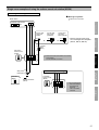
MOUNTING
This section illustrates the mounting procedures for wall- and ceiling-mount equipment.
■
Ceiling speaker (NI-LB)
■
Ceiling microphone (NI-SB)
ø105mm (4-3/16”)
66.7mm (2-11/16”)
NOTE:
Make sure to mount the ceiling microphone 50 cm (20") apart from the ceiling speaker to prevent audio feedback.
•
Pay attention to the depth of the unit.
•
Use board anchors or concrete plugs as needed on a concrete wall.
•
Holder
Hook
Connector
Loop
Main unit
Main unit
Spring
Ceiling
Ceiling
Ø150mm
(5-7/8")
Disconnect the connector,
2
and then make wire
connections with other
equipment.
Make a hole of 150mm (5-7/8")
1
in diameter in the ceiling.
Put the holder into
3
the hole by tilting it,
and then position it as
shown.
Hang the loop on the
4
hook at one side.
Connect the connector to
5
the main unit.
Hang the loop on the
6
hook
at the other side, and
install the main unit so
that it is positioned at the
center of the hole.
Wood screw x 2
(included)
Central part
Cut
1
the ceiling so that
the central part of the
unit fi ts in.
Make wire
2
connections with the
other equipment.
Fasten the unit to the
3
wall with the wood
screws.
W: 47mm (1-7/8")
Opening dimensions
H: 38mm
(1-1/2")
D: 40mm
(1-9/16")

15
MOUNTING CONNECTIONGETTING STARTED APPENDIX
SETUP AFTER
INSTALLATION
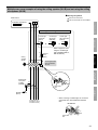
■
Wall jack (NIR-HP, NIR-1, NIR-MB, NIR-7BS)
Call button (NIR-6)
Corridor light (NIR-4, NIR-4S)
Call reset button (NIR-2)
The illustration shows the wall jack for NI-RC (NIR-HP).
*
Bathroom call button (NIR-7W, NIR-7HW)
The illustration shows the bathroom call button (NIR-7W).
*
CALL
Remove the front cover from
1
the main unit.
Install a single gang box
2
in the wall. Pass the wires
through the gang box and
make the wire connections
with the other equipment.
83.5mm
(3-5/16")
Single-gang box
Screw x 2
(included)
Main unit
Front cover
Fasten the unit to the single-
3
gang box with the screws.
Attach the front cover
4
to the main unit.
Install a single gang box
2
in the wall. Pass the wires
through the gang box and
make the wire connections
with the other equipment.
83.5mm (3-5/16")
Single-gang box
Screw x 2
(included)
Main unit
Front cover
Fasten the unit to the
3
single-gang box with the
screws.
The screw holes are on the
*
backside of gray rubber.
Attach the front cover to the main unit.
4
CALL
Remove the front cover
1
from the main unit.
Insert a fl at head screwdriver
into the hole on the bottom of
the unit, and then pull the fl at
head screwdriver toward you.
The front cover opens.
Flat head
screwdriver
Hole
H
D
W
H
D
W
Opening dimensions without a gang box
W: 45mm (1-3/4"), H: 72mm (2-13/16"),
D: 54mm (2-1/8")
Opening dimensions without a gang box
W: 50mm (1-15/16"), H: 70mm (2-3/4"),
D: 20mm (13/16")

16
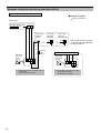
■
Sub station, surface mount (NI-BA)
When mounting NI-BA on a wall, follow the procedure shown below.
*
■
Sub station, fl ush mount (NI-JA)
Tighten
Special screw x 4
(included)
46 mm
(1-13/16'')
Loosen
Hexagonal wrench
(included)
Opening dimensions without a gang box
W: 90mm (3-9/16"), H: 73mm (2-7/8"), D: 54mm (2-1/8")
Main unit
2-gang box
Install a 2 gang box in the wall.
1
Pass the wires through the
gang box and make the wire
connections with the terminal
cover open.
Be sure to route the wires through
*
inlet.
Inlet Terminal cover
83.5 mm
(3-5/16'')
Fasten the main unit to
2
the gang box with the
special screws.
Install a single gang box in the wall. Pass the
1
wires through the gang box and make the wire
connections with the other equipment.
83.5mm (3-5/16")
Single-gang box
Screw x 2
(included)
Main unit
Fasten the mounting bracket to
2
the gang box with the screws.
Attach the main unit to
3
the mounting bracket.
Mounting bracket
(attached to NI-BA when shipped)
When setting NI-BA on a desk
Rubber foot
Cable inlet plate
Cable inlet
Cable inlet
Attach the included 4 rubber feet on the back
•
of NI-BA.
Route the wires through the cable inlet at the
•
upper or lower part of NI-BA.
When routing the wires at the upper part,
*
remove the cable inlet plate to allow
passage of the wires.

17
MOUNTING CONNECTIONGETTING STARTED APPENDIX
SETUP AFTER
INSTALLATION
■
Wall jack (NIR-HPF)
Corridor light (NIR-42, NIR-4BZ)
■
Corridor light with nameplate (NIR-31, NIR-32, NIR-34)
The illustration shows the corridor light with nameplates, 4 names (NIR-34).
*
Mounting bracket
(attached to the unit when shipped)
Main unit
Screw (for gang box) × 4 (included)
Single, 2- or 3-gang box
Install a gang box in the wall.
1
NIR-31, NIR-32: 2-gang box
(
*
)
NIR-34: 3-gang box
(
*
)
(
*
): Recommended
Detach the mounting
2
bracket from the main unit
by removing the room
number plate and the
screw.
Fasten the mounting
3
bracket to the gang box
with the screws.
String
Wires
Gang box
Main unit
Hang the string of
4
the main unit on a
projecting part or a
thread on the bracket
to suspend the main
unit.
Make wire connections
5
with other equipment.
Screw
(attached)
Room number
plate
46 mm
(1-13/16'')
2-gang box
Remove the front
1
cover from the
main unit.
Install a 2 gang box in
2
the wall. Pass the wires
through the gang box and
make the wire connections
with the other equipment.
83.5mm (3-5/16")
Screw x 4
(included)
Main unit
Front cover
Fasten the unit to the 2-gang
3
box with the screws.
Attach the front cover
4
to the main unit.
The illustration shows the
*
corridor light with reset
button (NIR-42).
Screw
(attached)
Room number
plate
Mount the main unit on the
6
mounting bracket, and affi x
the main unit to the bracket
with the screw.
Attach the room number
7
plate to the main unit
Opening dimensions without a gang box
W: 95mm (3-3/4"), H: 75mm (2-15/16"), D: 54mm (2-1/8")

18
CONNECTION
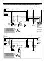
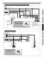
Connection wiring diagram (outline)
The following is an example of basic wiring diagram.
The wiring methods differ depending on the equipment used. Refer to page 20 to 29 for details about various wiring methods.*
E
1
M
2
3
4
5
10
12
19
20
11
SK
S1
SK
S1
I-G
RX
TX
Black
Orange
White
Gray
Orange/
White
Blue
Yellow
Red
Gray
White
PC
Blue
Blue
Blue
Blue
22
29
30
21
32
39
40
E
M
31
34
33
Gray
White
Blue
Blue
Red
White
Black
Black
Yellow
Red
Blue
or
NIR-8
NI-LB
Green
Black
Yellow
Red
Blue
Green
Black
Yellow
Red
Blue
Green
NI-RC
NIR-HP
NI-RC
NIR-HP
NIR-4
NIR-2
Blue
Blue
Black
Orange
White
Gray
Orange/
White
Blue
Yellow
Red
Blue
Blue
Blue
Blue
Corridor
light, single
bed
(NIR-4)
Call reset
button
(NIR-2)
Ceiling speaker
(NI-LB)
Master station,
40-call (NIM-40B)
When using the master
station, 60-call or 80-call,
two power supplies are
needed.
Do not connect two
power supplies in
parallel.
• Master station,
20-call (NIM-20B)
• Master station,
60-call
(
*
)
• Master station,
80-call
(
*
)
Call extension
speaker (IER-2)
Power supply
unit (IS-PU only)
RS232C
cable
(included on
NI-SOFT)
Ceiling
microphone
(NI-SB)
Wall jack
for NIR-8
(NIR-1)
Bedside
call switch
(NIR-8)
(6 wall jacks can be
connected in total.)
* Connect to
each of the
color-coded
wires.
* Connect to
each of the
color-coded
wires.
(6 wall jacks can be
connected in total.)
Refer to page 21 for
details about wiring to
a master station.
Refer to page 22 for details and examples of
using alternative equipment.
Refer to page 23 for details and examples of
using alternative equipment.
Wall jack with
microphone
for NIR-8
(NIR-MB)
Wall jack for
NI-RC (NIR-HP)
Bedside handheld sub station (NI-RC)
(
*
)
: Special order product.
N/A in North America.
Speaker etc.
(3W/20Ω,
third party
product)
SP-20N/A
(
*
)
(
*
)
: North America
only
(
*
1)
(
*
1)

19
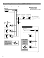
APPENDIX
MOUNTING CONNECTIONGETTING STARTED
SETUP AFTER
INSTALLATION
Red
Black
CALL
Blue
Green
Blue
Blue
Blue
Blue
Red
Black
Blue
Red
Black
Blue
CALL
CALL
Blue
Blue
Blue
Blue
II
Blue
Blue
Green
Green
Brown
Black
Black
Orange
Red
Red
Yellow
Blue
Green
NIR-7W or
NIR-7HW
NIR-7W or
NIR-7HW
NIR-7W or
NIR-7HW
Blue
Blue
Blue
Blue
E
C
CE
CS
M
A
NIR-4
NIR-2
NIR-4
NIR-2
NIR-8
NIR-1
NIR-4
NIR-2
CALL
E
C
CE
CS
M
A
■
Wiring distance
Wire diameter Maximum distance
Master station - sub station
Ø0.65mm (22 AWG)
Ø0.9mm (18 AWG)
130m (425')
200m (650')
Master station - power supply unit Ø0.9mm (18 AWG) 10m (33')
Master station - call extension
speaker (IER-2), speaker etc.
Ø0.9mm (18 AWG) 50m (165')
■
Master station terminal marking
E
: Common line (for earth ground)
M
: Common line (for microphone)
1
...
10
,
11
...
: Individual channel line
Refer to page 28 for details and examples
of using alternative equipment.
Refer to page 27 for
details and examples
of using alternative
equipment.
Refer to page 26 for details and examples
of using alternative equipment.
Refer to page 24-25 for
details and examples
of using alternative
equipment.
Refer to page 29 for
details about wiring to
the corridor light with
nameplate (NIR-34,
NIR-32 or NIR-31).
* Up to 3 bathroom
call buttons can be
connected to a single
channel line.
Bathroom
call button
(NIR-7W or
NIR-7HW)
Sub station,
surface mount
(NI-BA)
Sub station,
fl ush mount
(NI-JA)
Corridor light with
nameplates, 4
names
(NIR-34)
■
Meanings of symbols
: Wire-to-wire connection
: The wire should be cut and
insulated.
(
*
1)
: • The common line
E
and individual channel lines should be in the same sheath wiring.
• The remainder wires in the same sheath wiring should be connected to the common line
E
of the master station for noise prevention.

20
Handling cables
Notes about handling cables
Cables and connectors are not included with the products.
*
■
Notes on cables
Use PE (polyethylene)-insulated PVC jacketed cable.
•
Parallel or jacketed conductors, mid-capacitance, non-shielded cable
is recommended.
Never use twisted pair cable or coaxial cable.
•
■
How to connect or disconnect stranded wires.
To ensure that the wire won't bend, press the release button while inserting into terminal.
•
8mm
(3/8")
■
Note about wire-to-wire connection.
Make wire-to-wire connections securely as shown below.
e.g.) NI-BA
Release button
From a sub station
Wire nut
Cable
Splice 2 wires with wire nuts,
securely protecting from being
pulled or crushed.
e.g.) NIM-40B
Release button
Page is loading ...
Page is loading ...
Page is loading ...
Page is loading ...
Page is loading ...
Page is loading ...
Page is loading ...
Page is loading ...
Page is loading ...
Page is loading ...
Page is loading ...
Page is loading ...
-
 1
1
-
 2
2
-
 3
3
-
 4
4
-
 5
5
-
 6
6
-
 7
7
-
 8
8
-
 9
9
-
 10
10
-
 11
11
-
 12
12
-
 13
13
-
 14
14
-
 15
15
-
 16
16
-
 17
17
-
 18
18
-
 19
19
-
 20
20
-
 21
21
-
 22
22
-
 23
23
-
 24
24
-
 25
25
-
 26
26
-
 27
27
-
 28
28
-
 29
29
-
 30
30
-
 31
31
-
 32
32


Optimus NIM-20B User manual
- Type
- User manual
Ask a question and I''ll find the answer in the document
Finding information in a document is now easier with AI
Related papers
Other documents
-
Aiphone NIM Operating instructions
-
 Commercial Electric 217F WH User manual
-
 Commercial Electric B4684CW002 User manual
-
-
-
-
-
-
-
 Toyani TA-JY500 User manual


