Page is loading ...

Surge Protective Devices
SPD200K/300K Series

Safety Information
Important Information
Read these instructions carefully and look at the equipment to become
familiar with the device before trying to install, operate, service or maintain it.
The following special messages may appear throughout this bulletin or on the
equipment to warn of potential hazards or to call attention to information that
clarifies or simplifies a procedure.
The addition of either symbol to a “Danger” or “Warning” safety label
indicates that an electrical hazard exists which will result in personal
injury if the instructions are not followed.
This is the safety alert symbol. It is used to alert you to potential
personal injury hazards. Obey all safety messages that follow this
symbol to avoid possible injury or death.
DANGER
DANGER indicates a hazardous situation which, if not avoided,
will result in death or serious injury.
WARNING
WARNING indicates a hazardous situation which, if not avoided,
could result in death or serious injury.
CAUTION
CAUTION indicates a hazardous situation which, if not avoided,
could result in minor or moderate injury.
NOTICE
NOTICE is used to address practices not related to physical injury. The safety
alert symbol shall not be used with this signal word.
Please Note
Electrical equipment should be installed, operated, serviced, and maintained only
by qualified personnel. No responsibility is assumed by Appleton Grp LLC d/b/a
Appleton Group for any consequences arising out of the use of this material.
A qualified person is one who has skills and knowledge related to the
construction, installation, and operation of electrical equipment and has received
safety training to recognize and avoid the hazards involved.

Page: 1
SPD200K/300K
Precautions
DANGER
HAZARD OF ELECTRIC SHOCK, EXPLOSION, OR ARC FLASH
• Apply appropriate personal protective equipment (PPE) and follow safe electrical work practices. See NFPA 70E,
NOM-029-STPS or CSA Z462.
• This equipment must only be installed and serviced by qualied electrical personnel.
• Turn o all power supplying this equipment before working on or inside equipment.
• Always use a properly rated voltage sensing device to conrm power is o.
• Replace all devices, doors and covers before turning on power to this equipment.
• This equipment must be eectively grounded per all applicable codes. Use an equipment-grounding conductor to
connect this equipment to the power system ground.
Failure to follow these instructions will result in death or serious injury.
WARNING: This product can expose you to chemicals including DINP, which is known to the State of California
to cause cancer, and DIDP which is known to the State of California to cause birth defects or other reproductive
harm. For more information go to: www.P65Warnings.ca.gov.
NOTICE
LOSS OF BRANCH CIRCUIT POWER / LOSS OF SURGE SUPPRESSION
• Perform periodic inspection of the surge protective device status indicator lights as part of the preventative
maintenance schedule.
• Promptly replace the surge protective device when an alarm state exists.
• Use dry contacts to signal an alarm state to the central supervisory system for unmanned, inaccessible, or
critical installations.
• Use multiple surge protective devices to achieve redundancy for critical applications.
Failure to follow these instructions can result in equipment damage.
At end-of-life conditions, Surge Protective Devices (SPDs) can lose their ability to suppress power system
voltage and attempt to draw excessive current from the line. This SPD is equipped with overcurrent and
overtemperature components that will automatically disconnect the surge suppression elements from the
mains should the surge suppression elements reach end of life. Tripping of the branch circuit breaker or fuse
feeding the SPD can occur when the surge suppression elements reach end of life.

SPD200K/300K
Page: 2
DANGER
HAZARD OF ELECTRIC SHOCK, EXPLOSION, OR ARC FLASH
• Do not energize the surge protective device until the electrical system is completely installed, inspected and
tested.
• Ensure all conductors are connected.
• Verify the voltage rating of the device and system prior to energizing.
• Perform high-potential insulation testing, or any other tests where surge protective device components will be
subjected to voltages higher than their rated turn-on voltage, with the neutral and surge protective device discon-
nected from the power source
Failure to follow these instructions will result in death or serious injury.
Introduction
DANGER
HAZARD OF ELECTRIC SHOCK, EXPLOSION, OR ARC FLASH
• Apply appropriate personal protective equipment (PPE) and follow safe electrical work practices. See NFPA 70E,
NOM-029-STPS or CSA Z462.
• This equipment must only be installed and serviced by qualied electrical personnel.
• Turn o all power supplying this equipment before working on or inside equipment.
• Always use a properly rated voltage sensing device to conrm power is o.
• Replace all devices, doors and covers before turning on power to this equipment.
• This equipment must be eectively grounded per all applicable codes. Use an equipment-grounding conductor to
connect this equipment to the power system ground.
Failure to follow these instructions will result in death or serious injury.
Proper installation is imperative to maximize the SolaHD SPD200K/300K's effectiveness and performance.
Follow the steps outlined in this instruction manual to ensure proper installation. Read the entire instruction
manual before beginning the installation. These instructions are not intended to replace national or local
electrical codes. Check all applicable electrical codes to verify compliance. Installation of these surge
suppressors must only be performed by qualied electrical personnel.
Unpacking and Preliminary Inspection
Inspect the shipping container for damage before unpacking the device. Remove the packing material and
further inspect the device for shipping damage. If any damage is found, immediately le a claim with the
shipping company.
Storage
The device should be stored in a clean, dry environment. Storage temperature is -40°F (-40°C) to +140°F (+60°C). All
of the packaging materials should be left intact until the device is ready for installation.

Page: 3
SPD200K/300K
Surge Protective Device (SPD) Location Considerations
Environment
The device is designed to operate in an ambient temperature range of -25° C (-13° F) to +60° C (140° F) with a
relative humidity of 0 to 95% non- condensing.
Audible Noise
The device background noise is negligible and does not restrict the location of the installation.
Mounting
The device is designed to be surface mounted. Refer to the device submittal drawings or the product catalog
for typical mounting dimensions and weight.
Service Clearance
The service clearance must meet all applicable code requirements.
Equipment Performance
To obtain the maximum system performance, locate the device as close to the circuit being addressed as
possible to minimize the interconnecting wiring length. For every foot of wire length, approximately 160 Volts
(6 kV / 3 kA, 8/20 microsecond) is added to the suppressed voltage. The Voltage Protection Rating (VPR) is
located on the device nameplate and is measured six inches from the enclosure sidewall, according to
UL
®
1449 test standards.
Electrical
Voltage Rating
DANGER
HAZARD OF ELECTRIC SHOCK, EXPLOSION, OR ARC FLASH
• Conrm the SPD voltage rating on the module or nameplate label is not less than operating voltage the operating
voltage.
Failure to follow these instructions will result in death or serious injury.
Prior to mounting the SPD, verify that the device has the same voltage rating as the power distribution system
in which it is installed. Compare the nameplate voltage or model number on the SPD with the nameplate of
the electrical distribution equipment.
The specier or user of the device must be familiar with the conguration and arrangement of the power
distribution system in which any SPD is to be installed. The system conguration of any power distribution
system is based strictly on how the secondary windings of the transformer supplying the service entrance
main or load are congured. This includes whether or not the transformer windings are referenced to ground
via a grounding conductor. The system conguration is not based on how any specic load or equipment is
connected to a particular power distribution system. See Table 1 for the service voltage of each SPD.

SPD200K/300K
Page: 4
Table 1: Part Number Construction
SPD 200K or 300K oooRC
Surge Protective Device 200kA or 300kA Rating Per Phase Voltage Codes
10Y – 208Y/120V
27Y – 480Y/277V
24D – 240V Delta
48D – 480V Delta
34Y – 600Y/347V
60D – 600V Delta*
R = Internal Rotary Disconnect
C = LED(s)/Audible Alarm/Relay/ Surge Counter
Example: Part no. SPD200K10YRC is a 200kA, 120/208V Internal Rotary Disconnect and
LED(s)/Audible Alarm/Relay/Surge Counter
Available Part Number Combinations:
PARALLEL SPDs PARALLEL SPDs
SPD200K10YRC SPD300K10YRC
SPD200K27YRC SPD300K27YRC
SPD200K24DRC SPD300K24DRC
SPD200K48DRC SPD300K48DRC
SPD200K34YRC SPD300K34YRC
SPD200K60DRC
Figure 1: DELTA & HRG WYE Figure 2: WYE
Phase A (Black)
Phase C (Black)
Phase B (Black)
Ground (Green)
}
V
}
Phase A (Black)
Phase B (Black)
Neutral (White)
Phase C (Black)
Ground (Green)
A
C
N
V
B
DELTA & HRG WYE
3 Phase, 1 Ground
WYE
3 Phase, 1 Neutral, 1 Ground
*200K version only

Page: 5
SPD200K/300K
Terminals, Wire Size and Installation Torque
Terminals are provided for phase (line), neutral, and equipment ground connections.
Table 2: Terminal Torque
Connection Torque
Power Connection Torque
AØ, BØ, CØ, N and Ground 40–50 lb-in. ( 4.5–5.6 N•m)
Wire Size: 8 AWG to 1/0 AWG Copper
Location of Surge Protective Device (SPD)
Locate the SPD as close as possible to the circuit being addressed to minimize the wire length and optimize
SPD performance. Avoid long wire runs so that the device will perform as intended. To reduce wire impedance
from surge currents, the phase, neutral, and ground conductors must be routed within the same conduit and
tightly bundled or twisted together to optimize device performance. Avoid sharp bends in the conductors. See
Figure 3.
Figure 3: Surge Protective Device Wiring Practice
To load(s)
Phases
Neutral
Ground
Ground bus
Neutral bus
SPD
Phase A
Phase B
Phase C
Neutral
Ground
Panel
Interconnect wiring
– Minimize length
– Avoid sharp bends
Grounding
DANGER
HAZARD OF ELECTRIC SHOCK, EXPLOSION, OR ARC FLASH
• Connect the Surge Protective Device ground terminal to the building grounding grid structure.
• Use an appropriately sized equipment grounding conductor.
• Do not use isolated bushings to interrupt the metallic raceway or conduit.
• Maintain electrical continuity at all raceway and conduit connections using appropriate bonding devices.
• Do not use a separate isolated ground for this Surge Protective Device.
• Verify proper equipment connection to the grounding system.
• Verify ground grid continuity by performing regularly scheduled inspections and testing as part of a
comprehensive electrical maintenance program.
Failure to follow these instructions will result in death or serious injury.

SPD200K/300K
Page: 6
SPD DAMAGE AND POWER SYSTEM OVERVOLTAGE
• Ungrounded power systems are inherently unstable and can produce excessively high line-to-ground voltages
during certain fault conditions. During these fault conditions any electrical equipment, including an SPD, may be
subjected to voltages which exceed their designed ratings. This information is being provided to the user so that
an informed decision can be made before installing any electrical equipment on an ungrounded power system.
• Resistance-grounded power systems must be maintained in a over-damped state to limit voltage overshoot and
duration during operation.
• Verication and adjustment of correct power system damping should be done following power system
modications and periodically, as part normal system maintenance.
Failure to follow these instructions can result in injury or equipment damage.
General
The SolaHD SPD200K/300K has SPD elements connected from phase to ground. It is critical that there be a
robust and effective connection to the building grounding structure. The grounding connection must
utilize an equipment grounding conductor run with the phase and neutral (if present) connection of the
power system.
For proper over-voltage suppression by this SPD, use a single-point ground system where the service entrance
grounding electrode system is connected to, and bonded to, all other available electrodes, building steel,
metal water pipes, driven rods, etc. (for reference, see IEEE 142-2007). The ground impedance measurement
of the electrical system should be as low as possible, and in compliance with all applicable codes.
Solidly Grounded Power Systems
DANGER
HAZARD OF ELECTRIC SHOCK, EXPLOSION, OR ARC FLASH
• Do not connect devices rated for use on solidly-grounded power systems to resistance-grounded (for example,
High Resistance Ground) or ungrounded power systems.
• Verify that the service entrance equipment is bonded to ground in accordance with all applicable codes.
• Verify that the neutral terminal of the power system transformer feeding the device is bonded to system ground in
accordance with all applicable codes.
Failure to follow these instructions will result in death or serious injury.
SPDs rated for use on solidly-grounded power systems must not be connected to resistance-grounded or
ungrounded power systems. Such a connection can result in damage to the SPD.
Always verify the power system grounding conguration prior to application of power to the device. Conrm
that all ground bonds are installed at both the service entrance equipment and power system transformer
prior to application of power.
CAUTION

Page: 7
SPD200K/300K
Delta and Resistance-Grounded Power Systems
DANGER
HAZARD OF ELECTRIC SHOCK, EXPLOSION, OR ARC FLASH
• For resistance-grounded system maintain an over-damped state to limit voltage overshoot and duration during
operation.
• Verication and adjustment of correct power system damping should be done following power system modica-
tions and periodically, as part normal system maintenance.
Failure to follow these instructions will result in death or serious injury.
This product is intended for use on resistance-grounded power systems where the power system has been set
for, and is maintained in, an over-damped state. For the power system to be over-damped, the current through
the grounding resistor during a bolted phase-to-ground fault must be signicantly greater than the total
charging current of the system.
Periodic engineering evaluation of the power system is required to determine the worst-case charging current
of th e system and to adjust the grounding resistance accordingly. As the power system is modied, the value
of the grounding resistor must be evaluated and adjusted to maintain the system in the over-damped state.
Installation
DANGER
HAZARD OF ELECTRIC SHOCK, EXPLOSION, OR ARC FLASH
• Apply appropriate personal protective equipment (PPE) and follow safe electrical work practices. See NFPA 70E,
CSA Z462 or NOM-029-STPS.
• This equipment must only be installed and serviced by qualied electrical personnel.
• Turn o all power supplying this equipment before working on or inside equipment.
• Always use a properly rated voltage sensing device to conrm power is o.
• Replace all devices, doors and covers before turning on power to this equipment.
• This equipment must be eectively grounded per all applicable codes. Use an equipment-grounding conductor to
connect this equipment to the power system ground.
Failure to follow these instructions will result in death or serious injury.
Conduit Location and Recommendations
The recommended conduit entry is at the bottom or either side of the device enclosure. Use a conduit seal
that is appropriate for the enclosure rating.

SPD200K/300K
Page: 8
Module Rotation Feature
Installation lead wire length must be minimized because longer leads hurt performance. Lead length may be
reduced by rotating the module inside the enclosure. SPD ships with terminals pointing down. If installation
lends itself toward other orientation, the module’s aluminum backplane can be unscrewed and reoriented.
For example, if leads enter from top, rotate module assembly such that leads are shortest. Be careful with
ribbon cable connector and take care to retighten screws and secure ribbon cable. Mounting screws are in four
corners. Rectangular enclosures may be rotated up or down only.
Wiring
DANGER
HAZARD OF ELECTRIC SHOCK, EXPLOSION, OR ARC FLASH
• Apply appropriate personal protective equipment (PPE) and follow safe electrical work practices. See NFPA 70E,
CSA Z462 or NOM-029-STPS.
• This equipment must only be installed and serviced by qualied electrical personnel.
• Turn o all power supplying this equipment before working on or inside equipment.
• Always use a properly rated voltage sensing device to conrm power is o.
• Replace all devices, doors and covers before turning on power to this equipment.
• This equipment must be eectively grounded per all applicable codes. Use an equipment-grounding conductor to
connect this equipment to the power system ground.
• Conrm the SPD voltage rating on the module or nameplate label is not less than the operating voltage.
Failure to follow these instructions will result in death or serious injury.
The SPD200K/300K Series
Follow steps 1 through 7 to make wiring connections to units with rotary disconnect switch:
1. Turn off all power supplying this equipment before working on or inside any enclosure containing this
equipment.
2. Conrm SPD is rated for your system by comparing voltage measurements to the Line Voltage (L-L, L-N) on
the product label.
3. Identify proper location for surge protective device. Locate as close as possible to the panel being
addressed so the wires are as short as possible. Mount unit securely.
Note: The surge protective device must be installed in an accessible location as described in the NEC.

Page: 9
SPD200K/300K
4. Install in accordance with national and local electrical codes for overcurrent protection recommendations
and wire ampacity considerations.
Note: Use on solidly grounded systems unless the SPD model is designed for installation on ungrounded
/HRG systems.
Note: See “Terminals, Wire Size, and Installation Torque” and Table 2 on page 5 for acceptable wire size and
installation torque.
5. Twist conductors 1/2 turn or more for every twelve inches of length. Do not loop or coil wires. Be sure to
maintain adequate wire bending space per NEC.
6. If the remote signaling contacts of the diagnostic display panel are to be used, refer to the section, “Dry
Contacts,” on page 14 for wiring instructions.
7. Replace all devices, doors, and covers before turning on power to the equipment. If the SPD is properly
installed and functioning, the green LED indicators on the display will be lit and the service LED
extinguished.
If you have any questions pertaining to the installation of this device, contact us at 1-800-377-4384
or solahd.technicalservices@emerson.com.
Dimensions and Weights
Model H/W/D (in. / mm.) Weight
SPD200K / SPD300K
12" x 12" x 6" (305 x 305 x 152) 23 lbs (10.4 kg)
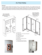
Figure 8: Typical Panel Installation
When breaker connecting, use
closest breaker to SPD
Locate SPD close
to intended breaker
Keep Leads Short as Possible
Avoid Sharp Bends
Outdoor installation requires
appropriate weather sealing
at nipple (gasket, sealing
conduit, etc.)
To Protected Loads
A
BC
G
N
BREAKER

SPD200K/300K
Page: 10
Figure 4: Three-Phase, Three- or Four-Wire, Grounded Wye Installation with Integral Switch
If the neutral conductor is not present on three-wire
grounded power systems. For these systems (Wye, no
neutral), bond the neutral and ground lugs together
inside the SPD using 10 AWG wire.
A
2
1
3
4 6
5
7
8
B
C
N
A
B
C
N
AB NC
G
THREE POLE
C
N
G
A
TWO POLE
2
1
3
46
5
7
8
G
CB NA
THREE POLE W/ DS
N
G
B
SINGLE POLE
C
N
G
BA
THREE POLE
SPD
PHASE C
PHASE A
PHASE B
NEUTRAL
GROUND
N
A
B
C
Wiring Diagrams With Disconnect Switch
NOTICE
HAZARD OF LOSS OF PROPERLY FUNCTIONING LED/ALARM/STATUS
• Bond the ground and neutral lugs with a 10 AWG wire when connected to no-neutral power sources only.
Failure to follow these instructions can result in equipment damage.

Page: 11
SPD200K/300K
Figure 5: Three-Phase, Three-Wire + Ground, Delta Installation
The ground connection of the Delta SPD shall be connected to the system ground conductor. The
neutral conductor is not present on Delta systems.
Phase B of the electrical system is typically the grounded phase
A
2
1
3
4 6
5
7
8
B
C
N
A
B
C
N
AB NC
G
THREE POLE
C
N
G
A
TWO POLE
2
1
3
46
5
7
8
G
CBA
THREE POLE W/ DS
N
G
B
SINGLE POLE
C
N
G
BA
THREE POLE
SPD
Ground
Phase B
Phase C
Phase A
B
A
C
Corner Grounded Delta
SPD
Ground
Phase B
Phase C
Phase A
B
A
C
Ungrounded Delta

SPD200K/300K
Page: 12
UL 1283 Required Language Concerning the Installation of EMI Filters
(Standard on SPD200K/300K)
A. An insulated grounding conductor that is identical in size and insulation material and thickness to the
grounded and ungrounded circuit supply conductors, except that it is green with or without one or more
yellow stripes, is to be installed as part of the circuit that supplies the lter. Reference should be made to
Table 250-122 of the National Electrical Code regarding the appropriate size of the grounding conductor.
B. The grounding conductor mentioned in item a is to be grounded at the service equipment or other
acceptable building ground such as the building frame in the case of a high-rise steel frame structure.
C. Any attachment-plug receptacles in the vicinity of the lter are to be of a grounding type, and the
grounding conductors serving these receptacles are to be connected to ground at the service equipment
or other acceptable building ground such as the building frame in the case of a high-rise steel-frame
structure.
D. Pressure terminal or pressure splicing connectors and soldering lugs used in the installation of the lter
shall be identied as being suitable for the material of the conductors. Conductors of dissimilar metals
shall not be intermixed in a terminal or splicing connector where physical contact occurs between
dissimilar conductors unless the device is identied for the purpose and conditions of use.
Operation
DANGER
HAZARD OF ELECTRIC SHOCK, EXPLOSION, OR ARC FLASH
• Apply appropriate personal protective equipment (PPE) and follow safe electrical work practices. See NFPA 70E,
CSA Z462 or NOM-029-STPS.
• This equipment must only be installed and serviced by qualied electrical personnel.
• Turn o all power supplying this equipment before working on or inside equipment.
• Always use a properly rated voltage sensing device to conrm power is o.
• Replace all devices, doors and covers before turning on power to this equipment.
• This equipment must be eectively grounded per all applicable codes. Use an equipment-grounding conductor to
connect this equipment to the power system ground.
Failure to follow these instructions will result in death or serious injury.
LED Status Indicators
The SPD diagnostic display panel shows the status of each phase of the SPD with diagnostically controlled
green/red LEDs). If a unit is operating correctly, all of the phase LEDs will be illuminated green. To test the
integrity of the diagnostics for each phase, push the button below the phase LEDs on the diagnostic display
panel. The green LED will turn red and the alarm will sound, if the alarm is enabled. Releasing the test button
will complete the test; the red LED will turn green and the alarm will shut off.
If an inoperable condition occurs on any phase, the audible alarm sounds and the corresponding phase LED on
the diagnostic display panel is extinguished and the service light will illuminate. This indicates that the device
needs service by qualied electrical personnel.
The audible alarm can be silenced, until a qualied person is able to evaluate and service the SPD, by pressing
the alarm silence button. The alarm will silence and the LED above the buttom will be lit. The red service LED
will continue to be illuminated until the inoperative condition had been cleared.

Page: 13
SPD200K/300K
Figure 6: Diagnostic Display Panel
Phase A, B & C: Green LED indicators—one per phase. Green is good. Out indicates problem. Every
suppression element in this SPD is monitored. (N-G indicates on Phase A)
Service LED (Red): LED illuminates in the event of problems. This indicator is logic-connected to the Phase
LEDs. Should a Phase LED go out the Service LED will illuminate and the Audible Alarm will sound.
Test: Tests red Service LED and Audible Alarm, and changes state of Dry Contacts.
Alarm Silence: Turns Audible Alarm off. (Alarm is deactivated when the Silence LED is illuminated.)
Surge Counter Count: Increments optional surge counter by one. (+1)
Surge Counter Reset: Resets optional surge counter to zero. (0)
Audible Alarm
Push the alarm silence button to enable or disable the alarm (see Figure 6). If the service LED is lit the alarm is
enabled. If the service LED is not lit the alarm is disabled.
Surge Counter
The surge counter displays the number of transient voltage surges since the counter was last reset. The
counter is battery powered to retain memory in the event of a power loss to the SPD. To reset the surge
counter, press the button on the front display. This will reset the counter to zero. To test the surge counter
functionality press the count button located on the front panel. This will incrementally increase the surge
counter by one.

SPD200K/300K
Page: 14
Dry Contacts
DANGER
HAZARD OF ELECTRIC SHOCK, EXPLOSION, OR ARC FLASH
• Use 600 Vac rated dry contact wiring.
• Dry contact wiring must have less than 1/16 in. (1.6 mm) exposed wire from the dry contact block.
• Do not supply more than 24 V dc / 24 V ac and no more than a current of 2 A.
Failure to follow these instructions will result in death or serious injury.
The SolaHD 200K/300K series SPD is provided with dry contacts. The connection for the dry contacts is
located on the inside of the SPD enclosure and will accept # 22 - 14 AWG stranded or solid wire. The dry
contacts are three-position, Form “C” type with Normally Open, Normally Closed, and Common connections.
In the unpowered state the contact is closed between terminals NC and COM. This is also the alarm condition.
The opposite state, closed between terminals NO and COM, indicates that power is on to the unit and that no
alarm condition exists.
Figure 7: Dry Contact Option
NO
DRY CONTACTS
NC NC C NOC
These contacts can be used for remote indication of the SPD’s operating status to a computer interface board
or emergency management system. Also, these contacts are designed to work with the SPD remote monitor
option described in the next section.
Table 3: Dry Contact Configuration
Alarm Contact Terminals Contact State with Power Applied
NO to COM Closed
NC to COM Open
The dry contacts are designed for a maximum voltage of 24 Vdc / 24 Vac and a maximum current of 2 A. For
application questions, contact us at 1-800-377-4384 or solahd.technicalservices@emerson.com.

Page: 15
SPD200K/300K
Maintenance and Troubleshooting
DANGER
HAZARD OF ELECTRIC SHOCK, EXPLOSION, OR ARC FLASH
• Apply appropriate personal protective equipment (PPE) and follow safe electrical work practices. See NFPA 70E,
CSA Z462 or NOM-029-STPS.
• This equipment must only be installed and serviced by qualied electrical personnel.
• Turn o all power supplying this equipment before working on or inside equipment.
• Always use a properly rated voltage sensing device to conrm power is o.
• Replace all devices, doors and covers before turning on power to this equipment.
• This equipment must be eectively grounded per all applicable codes. Use an equipment-grounding conductor to
connect this equipment to the power system ground.
Failure to follow these instructions will result in death or serious injury.
Preventative Maintenance
Inspect the SPD periodically to help maintain system performance and continued transient voltage surge
suppression. Periodically check the state of the diagnostic display panel LED status indicators. Routinely use
the built-in diagnostics to inspect for inoperative modules.
Troubleshooting
This surge protector has little to troubleshoot. If a phase LED in extinguished or the service light is on please
contact us.
For application questions, contact us at 1-800-377-4384 or solahd.technicalservices@emerson.com.
Replacement Parts
The module is eld replaceable. Deenergize SPD, conrm with appropriate measurement equipment and
discharge internal capacitance to ground. Mark locations and carefully disconnect diagnostic cables, dry
contact connections, phase conductors, unplug parallel connections on SPD200K/300K models, etc. Reinstall
in reverse order.
There are no user serviceable parts inside the module. We strongly recommend against disassembly.
Modules may be returned to the factory for factory service, qualication and return. Please contact us
at 1-800-377-4384 for assistance.

SPD200K/300K
Page: 16

Page: 17
SPD200K/300K
Technical Support
Website: www.solahd.com
Technical Support E-Mail: solahd.technicalservices@emerson.com
Toll-Free: (800) 377-4384
USA: (847) 268-6651
Warranty
Please refer to the “Terms & Conditions of Sale” document.
While every precaution has been taken to ensure accuracy and completeness in this manual, Appleton Grp LLC d/b/a Appleton Group
assumes no responsibility, and disclaims all liability for damages resulting from use of this information or for any errors or omissions.

SPD200K/300K Series
A272-328 Rev. 0 12/2020
The Emerson logo is a trademark and service mark of Emerson Electric Co.
Appleton Grp LLC d/b/a Appleton Group. SolaHD is a registered trademark of Appleton Grp LLC.
All other marks are the property of their respective owners. © 2020 Emerson Electric Co. All rights reserved.
United States
(Headquarters)
Appleton Grp LLC
9377 W. Higgins Road
Rosemont, IL 60018
United States
T +1 800 621 1506
Australia Sales Office
Bayswater, Victoria
T +61 3 9721 0348
Europe
ATX SAS
Espace Industriel Nord
35, rue André Durouchez,
CS 98017
80084 Amiens Cedex 2
France
T +33 3 2254 1390
China Sales Office
Shanghai
T +86 21 3338 7000
Canada
EGS Electrical Group Canada
Ltd.
99 Union Street
Elmira ON, N3B 3L7
Canada
T +1 888 765 2226
Middle East Sales Office
Dammam, Saudi Arabia
T +966 13 510 3702
Chile Sales Office
Las Condes
T +56 2928 4819
India Sales Office
Chennai
T +91 44 3919 7300
Korea Sales Office
Seoul
T +82 2 3483 1555
PN# 9645_r-
Asia Pacific
EGS Private Ltd.
Block 4008, Ang Mo Kio
Ave 10,
#04-16 TechPlace 1,
Singapore 569625
T +65 6556 1100
Latin America
EGS Comercializadora
Mexico S de RL de CV
Calle 10 N°145 Piso 3
Col. San Pedro de los Pinos
Del. Álvaro Obregon
Ciudad de México. 01180
T +52 55 5809 5049
/