Page is loading ...

Operating instructions
EN
Electrode grinding machine
TGM 40230 Porta 230V 50Hz
099-003694-EW501
04.05.2017
Register now
and benefit!
Jetzt Registrieren
und Profitieren!
www.ewm-group.com
*For details visit
www.ewm-group.com
*

General instructions
WARNING
Read the operating instructions!
The operating instructions provide an introduction to the safe use of the products.
• Read and observe the operating instructions for all system components, especially the
safety instructions and warning notices!
• Observe the accident prevention regulations and any regional regulations!
• The operating instructions must be kept at the location where the machine is operated.
• Safety and warning labels on the machine indicate any possible risks.
Keep these labels clean and legible at all times.
• The machine has been constructed to state-of-the-art standards in line with any applicable
regulations and industrial standards. Only trained personnel may operate, service and
repair the machine.
• Technical changes due to further development in machine technology may lead to a
differing welding behaviour.
In the event of queries on installation, commissioning, operation or special conditions at the
installation site, or on usage, please contact your sales partner or our customer service
department on +49 2680 181-0.
A list of authorised sales partners can be found at www.ewm-group.com.
Liability relating to the operation of this equipment is restricted solely to the function of the
equipment. No other form of liability, regardless of type, shall be accepted. This exclusion of
liability shall be deemed accepted by the user on commissioning the equipment.
The manufacturer is unable to monitor whether or not these instructions or the conditions and
methods are observed during installation, operation, usage and maintenance of the equipment.
An incorrectly performed installation can result in material damage and injure persons as a
result. For this reason, we do not accept any responsibility or liability for losses, damages or
costs arising from incorrect installation, improper operation or incorrect usage and maintenance
or any actions connected to this in any way.
© EWM AG
Dr. Günter-Henle-Straße 8
56271 Mündersbach
Germany
The copyright to this document remains the property of the manufacturer.
Copying, including extracts, only permitted with written approval.
The content of this document has been prepared and reviewed with all reasonable care. The information
provided is subject to change; errors excepted.

Contents
Notes on the use of these operating instructions
099-003694-EW501
04.05.2017
3
1 Contents
1 Contents .................................................................................................................................................. 3
2 For your safety ....................................................................................................................................... 4
2.1 Notes on the use of these operating instructions .......................................................................... 4
2.2 Explanation of icons ....................................................................................................................... 5
2.3 General .......................................................................................................................................... 5
3 Intended use ........................................................................................................................................... 7
3.1 Applications .................................................................................................................................... 7
3.2 Documents which also apply ......................................................................................................... 7
3.2.1 Warranty ......................................................................................................................... 7
3.2.2 Declaration of Conformity ............................................................................................... 7
3.2.3 Service documents (spare parts) ................................................................................... 7
4 Machine description .............................................................................................................................. 8
5 Design and function ............................................................................................................................... 9
5.1 Transport and installation .............................................................................................................. 9
5.1.1 Ambient conditions ......................................................................................................... 9
5.1.1.1 In operation ................................................................................................... 10
5.1.1.2 Transport and storage ................................................................................... 10
5.1.2 Presets ......................................................................................................................... 10
5.1.2.1 Topping up the grinding liquid ....................................................................... 11
5.1.2.2 Preparing electrodes for the grinding process .............................................. 12
5.1.2.3 Setting the grinding angle of the tungsten electrode .................................... 13
5.2 Grinding the electrode ................................................................................................................. 13
6 Maintenance and care .......................................................................................................................... 14
6.1 Cleaning ....................................................................................................................................... 14
6.2 Replacing the grinding disk .......................................................................................................... 15
7 Technical data ...................................................................................................................................... 16
7.1 TGM 40230 – PORTA.................................................................................................................. 16
8 Accessories .......................................................................................................................................... 17
8.1 Replaceable parts ........................................................................................................................ 17
9 Appendix A ........................................................................................................................................... 18
9.1 Overview of EWM branches ........................................................................................................ 18

For your safety
Notes on the use of these operating instructions
4
099-003694-EW501
04.05.2017
2 For your safety
2.1 Notes on the use of these operating instructions
DANGER
Working or operating procedures which must be closely observed to prevent imminent
serious and even fatal injuries.
• Safety notes include the "DANGER" keyword in the heading with a general warning symbol.
• The hazard is also highlighted using a symbol on the edge of the page.
WARNING
Working or operating procedures which must be closely observed to prevent serious
and even fatal injuries.
• Safety notes include the "WARNING" keyword in the heading with a general warning
symbol.
• The hazard is also highlighted using a symbol in the page margin.
CAUTION
Working or operating procedures which must be closely observed to prevent possible
minor personal injury.
• The safety information includes the "CAUTION" keyword in its heading with a general
warning symbol.
• The risk is explained using a symbol on the edge of the page.
Special technical points which users must observe.
Instructions and lists detailing step-by-step actions for given situations can be recognised via bullet
points, e.g.:
• Insert the welding current lead socket into the relevant socket and lock.

For your safety
Explanation of icons
099-003694-EW501
04.05.2017
5
2.2 Explanation of icons
Symbol
Description
Symbol
Description
Indicates technical aspects which the
user must observe.
Activate and release/tap/tip
Switch off machine
Release
Switch on machine
Press and keep pressed
Switch
Wrong
Turn
Correct
Numerical value – adjustable
Menu entry
Signal light lights up in green
Navigating the menu
Signal light flashes green
Exit menu
Signal light lights up in red
Time representation (e.g.: wait
4 s/activate)
Signal light flashes red
Interruption in the menu display (other
setting options possible)
Tool not required/do not use
Tool required/use
2.3 General
WARNING
Risk of accidents due to non-compliance with the safety instructions!
Non-compliance with the safety instructions can be fatal!
• Carefully read the safety instructions in this manual!
• Observe the accident prevention regulations and any regional regulations!
• Inform persons in the working area that they must comply with the regulations!
CAUTION
Noise exposure!
Noise exceeding 70 dBA can cause permanent hearing damage!
• Wear suitable ear protection!
• Persons located within the working area must wear suitable ear protection!

For your safety
General
6
099-003694-EW501
04.05.2017
The respective national directives and laws must be observed when operating the machine!
• National implementation of the framework directive (89/391/EWG), as well as the associated
individual directives.
• In particular, the directive (89/655/EWG) on the minimum regulations for safety and health
protection when staff members use equipment during work.
• The regulations regarding occupational safety and accident prevention for the respective
country.
• Check at regular intervals that users are adhering to the safety regulations in their work.
• Check the machine at regular intervals according to BGV A3.
The manufacturer's warranty becomes void if non-genuine parts are used!
• Only use system components and options (power sources, welding torches, electrode
holders, remote controls, spare parts and replacement parts, etc.) from our range of products!
• Only insert and lock accessory components into the relevant connection socket when the
machine is switched off.

Intended use
Applications
099-003694-EW501
04.05.2017
7
3 Intended use
WARNING
Hazards due to improper usage!
The machine has been constructed to the state of the art and any regulations and
standards applicable for use in industry and trade. It may only be used for the welding
procedures indicated at the rating plate. Hazards may arise for persons, animals and
material objects if the equipment is not used correctly. No liability is accepted for any
damages arising from improper usage!
• The equipment must only be used in line with its designated purpose and by trained or
expert personnel!
• Do not improperly modify or convert the equipment!
3.1 Applications
Grinder for TIG electrodes.
3.2 Documents which also apply
3.2.1 Warranty
For more information refer to the "Warranty registration" brochure supplied and our information
regarding warranty, maintenance and testing at www.ewm-group.com!
3.2.2 Declaration of Conformity
The labelled machine complies with the following EC directives in terms of its design and
construction:
• Machine directive
• Low Voltage Directive (LVD)
• Electromagnetic Compatibility Directive (EMC)
• Restriction of Hazardous Substance (RoHS)
In case of unauthorised changes, improper repairs, non-compliance with specified deadlines for "Arc
Welding Equipment – Inspection and Testing during Operation", and/or prohibited modifications which
have not been explicitly authorised by EWM, this declaration shall be voided. An original document of the
specific declaration of conformity is included with every product.
3.2.3 Service documents (spare parts)
WARNING
Do not carry out any unauthorised repairs or modifications!
To avoid injury and equipment damage, the unit must only be repaired or modified by
specialist, skilled persons!
The warranty becomes null and void in the event of unauthorised interference.
• Appoint only skilled persons for repair work (trained service personnel)!
Spare parts can be obtained from the relevant authorised dealer.

Machine description
Documents which also apply
8
099-003694-EW501
04.05.2017
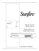
4 Machine description
Figure 4-1
Item
Symbol
Description 0
1
Grinding disk
2
Inspection glass
3
Filling hose
4
Mains connection cable
5
Dust container
6
Indication of correct liquid level
7
Machine table
8
Depth gauge setting bolt
9
Collet chuck
10
Electrode holder
Area of application: unalloyed and low-alloy materials
11
On/off switch
12
Torch body
13
Grinding angle scale
14
Infeed channel
15
Brass disc
16
Allen screw
17
Depth gauge

Design and function
Transport and installation
099-003694-EW501
04.05.2017
9
5 Design and function
WARNING
Harmful electrode material!
Electrodes may contain harmful substances!
• Observe the instructions by the electrode manufacturer!
CAUTION
Open infeed channel!
If the infeed channel is left open, chips and dirt particles can be expelled from the
channel when the grinding disk is running and might get into the eyes or be breathed
in!
• Place the electrode holder in the infeed channel before switching on.
• Allow the grinding disk to come to a stop after switching off before removing the electrode
holder from the infeed channel.
Starting with electrode against grinding disc!
If the grinder is started while the electrode lies against the grinding disc, the electrode
can jam and cause damage to the disc, the machine and people!
• When starting the grinder, make sure the electrode does not lie against the grinding disc!
• Before starting the grinder, check the electrode position through the inspection window!
If too much pressure is exerted from the electrode onto the grinding disk, the electrode may
overheat and become annealed. An annealed electrode can become unusable and damage the
machine!
• Do not press the electrode too forcefully against the grinding disk!
• Turn the electrode evenly during the grinding process!
5.1 Transport and installation
CAUTION
Risk of accidents due to supply lines!
During transport, attached supply lines (mains leads, control cables, etc.) can cause
risks, e.g. by causing connected machines to tip over and injure persons!
• Disconnect all supply lines before transport!
5.1.1 Ambient conditions
Unusually high quantities of dust, acid, corrosive gases or substances may damage the
equipment.
• Avoid high volumes of smoke, vapour, oil vapour and grinding dust!
• Avoid ambient air containing salt (sea air)!
Insufficient ventilation results in a reduction in performance and equipment damage.
• Observe the ambient conditions!
• Keep the cooling air inlet and outlet clear!
• Observe the minimum distance of 0.5 m from obstacles!

Design and function
Transport and installation
10
099-003694-EW501
04.05.2017
5.1.1.1 In operation
Temperature range of the ambient air:
• -25 °C to +40 °C
Relative air humidity:
• Up to 50% at 40 °C
• Up to 90% at 20 °C
5.1.1.2 Transport and storage
Storage in an enclosed space, temperature range of the ambient air:
• -30 °C to +70 °C
Relative air humidity
• Up to 90% at 20 °C
5.1.2 Presets
CAUTION
Complete assembly!
The machine must only be used with all the add-on parts fitted to the casing. Operating
the machine when incomplete can result in damage and injury.
• Check that all components are fitted correctly before operation!

Design and function
Transport and installation
099-003694-EW501
04.05.2017
11
5.1.2.1 Topping up the grinding liquid
Operating without grinding liquid!
The machine is not factory-filled with grinding liquid. The machine must not be operated without
grinding liquid!
• Top up the grinding liquid before commissioning!
Figure 5-1
Item
Symbol
Description 0
1
Grinding disk
2
Grease nipple plug
3
Filling hose
4
Inspection glass
5
Indication of correct liquid level
6
Dust container
7
Drain thread
8
Machine table
• Unfasten the locking screw from the drain thread.
• Manually screw the duct collector to the drain thread.
• Remove the lubricating nipple plug from the filling hose.
• Place the grinding liquid container inlet onto the filling hose.
• Refill grinding liquid.
• Observe the indication of the correct liquid level in the inspection window (do not exceed)!
Do not transport the grinder with grinding liquid filled in!
• Drain the grinding liquid into a container that can be tightly closed!

Design and function
Transport and installation
12
099-003694-EW501
04.05.2017
5.1.2.2 Preparing electrodes for the grinding process
Various collet chucks modified to the electrode diameter should be used to secure the electrodes for the
grinding process.
CAUTION
Incorrect collet chuck!
Using a collet chuck that does not match the electrode size can mean that the electrode
may become loose, the machine damaged and can also result in injury.
• Only use genuine collet chucks!
• Only use collet chucks that match the relevant electrode diameter!
Figure 5-2
Item
Symbol
Description 0
1
Electrode
2
Collet chuck
3
Electrode holder
Area of application: unalloyed and low-alloy materials
• Select the collet chuck according to the electrode diameter.
• Insert the electrode into the collet chuck.
• Screw the collet chuck into the electrode holder.
Figure 5-3
Item
Symbol
Description 0
1
Depth gauge setting bolt
Depth gauge setting bolt
The setting bolt on the rear of the depth gauge can be used to set the grinding of the tungsten
electrode.
• Rotate out: More grinding
• Rotate in: Less grinding

Design and function
Grinding the electrode
099-003694-EW501
04.05.2017
13
5.1.2.3 Setting the grinding angle of the tungsten electrode
The grinding angle is set via the indicator mark on the infeed. Half angles of 7.5 to 90° can be set.
Figure 5-4
Item
Symbol
Description 0
1
Infeed
2
Grinding angle scale
3
Carrying handle
4
Mark
• Unfasten the knurled screw on the infeed.
• Set the mark on the infeed to the required half angle.
• Tighten the knurled screw hand-tight.
5.2 Grinding the electrode
A faulty grinding disc can cause damage to the electrode and electrode holder.
• Do not use the grinder if the grinding disc is damaged.
• Use original grinding discs only.
• Check that the on/off switch is in the "0" position.
• Connect the machine to the power supply.
• Check through the inspection glass that the electrode is not positioned against the grinding disk.
• Switch on machine.
• Move the electrode holder onto the grinding disk while turning it slowly, so that the tungsten electrode
does not anneal. Check the process through the inspection glass.
• Complete the grinding process using light pressure and slow even rotation of the electrode holder.
• The grinding process is complete when the electrode holder limit stop has been reached.
• Switch off the machine and allow it to come to a stop.
• Remove the electrode holder from the infeed channel.
• Insert the electrode holder into the depth gauge and unfasten the electrode by turning to the left.

Maintenance and care
Cleaning
14
099-003694-EW501
04.05.2017
6 Maintenance and care
6.1 Cleaning
WARNING
Mains voltage!
Before carrying out any cleaning or testing measures, ensure that all mains connections
and supply lines of the machine are disconnected.
• Disconnect all mains connections and supply lines.
CAUTION
Grinding dust!
Grinding dust may get into the eyes during cleaning. Grinding liquid residue can enter
the bloodstream via surface skin wounds.
• Wear safety glasses and protective gloves during cleaning!
Figure 6-1
Item
Symbol
Description 0
1
Inspection glass frame screws
2
Indication of correct liquid level
3
Allen screw
4
Brass disc
5
Grinding disk
6
Inspection glass frame

Maintenance and care
Replacing the grinding disk
099-003694-EW501
04.05.2017
15
• Disconnect the grinding machine from the mains.
• Draw off the grinding liquid in an appropriate container.
• Disassemble the dust container.
• Remove the screws on the inspection glass frame.
• Remove the inspection glass and inspection glass frame.
• Clean the grinding chamber using clean water.
• Top up the cleaning water in a suitable container and dispose of in accordance with regulations.
• Re-fit the inspection glass and inspection glass frame using the screws.
• Make sure the sealing ring fits tightly between casing and inspection glass.
6.2 Replacing the grinding disk
• Disconnect the grinding machine from the mains.
• Draw off the grinding liquid into an appropriate container.
• Remove the inspection glass and inspection glass frame.
• Remove the Allen screw ( left-hand thread) in the centre of the grinding disk.
• Remove the brass disk.
• Replace the grinding disk.
• Re-fit the brass disk using the Allen screw.
• Re-fit the inspection glass and inspection glass frame.
• Top up the grinding liquid.
• Make sure the sealing ring fits tightly between casing and inspection glass.

Technical data
TGM 40230 – PORTA
16
099-003694-EW501
04.05.2017
7 Technical data
7.1 TGM 40230 – PORTA
Mains cable length
2 m
Output
380 W
Mains connection (EN 50144)
230 V, 50/60 Hz
Speed
8500 rpm
Diamond disk diameter
40 mm
Grinding speed
44 m/s
Grinding angle setting
7.5 °-90 °
Grinding liquid fill capacity
250 ml
Weight
9.3 kg
Harmonised standards used
EN 61029
Safety identification

Accessories
Replaceable parts
099-003694-EW501
04.05.2017
17
8 Accessories
8.1 Replaceable parts
Using replacement parts which are not genuine, such as grinding disks and grinding concentrate,
may shorten the service life of the machine and void the warranty. Use only genuine replacement
parts!
Type
Designation
Item no.
COL Porta/Handy Ø 0.8 mm
Collet chuck for EWM tungsten electrode grinders
098-003696-00000
COL Porta/Handy Ø 1.0 mm
Collet chuck for EWM tungsten electrode grinders
098-003697-00000
COL Porta/Handy Ø 1.2 mm
Collet chuck for EWM tungsten electrode grinders
098-003698-00000
COL Porta/Handy Ø 1.6 mm
Collet chuck for EWM tungsten electrode grinders
098-003674-00000
COL Porta/Handy Ø 2.0 mm
Collet chuck for EWM tungsten electrode grinders
098-003675-00000
COL Porta/Handy Ø 2.4 mm
Collet chuck for EWM tungsten electrode grinders
098-003676-00000
COL Porta/Handy Ø 3.2 mm
Collet chuck for EWM tungsten electrode grinders
098-003677-00000
COL Porta/Handy Ø 4.0 mm
Collet chuck for EWM tungsten electrode grinders
098-003678-00000
Diamond grinding disk
Grinding disk
098-003695-00000
Grinding concentrate, 250 ml
Grinding concentrate
098-003699-00000

Appendix A
Overview of EWM branches
18
099-003694-EW501
04.05.2017
9 Appendix A
9.1 Overview of EWM branches
/