Page is loading ...

VCS500 AND VCS550 SERIES
HB0181
INSTALLATION INSTRUCTIONS
INTENDED FOR DOMESTIC COOKING ONLY
INSTALLER: LEAVE THIS MANUAL WITH HOMEOWNER.
HOMEOWNER: USE AND CARE INFORMATION ON PAGES 13 AND 14.
READ AND SAVE THESE INSTRUCTIONS
Venmar Ventilation ULC, 550 Lemire Blvd., Drummondville QC J2C 7W9 1-800-567-3855
REGISTER YOUR PRODUCT ONLINE AT: www.bnv.ca
For additional information - visit www.venmar.ca
22745 rev. 07
! !

2
TO REDUCE THE RISK OF FIRE, ELECTRIC SHOCK OR
INJURY TO PERSONS, OBSERVE THE FOLLOWING:
1. Use this unit only in the manner intended by the manufacturer.
If you have questions, contact the manufacturer at the address
or telephone number listed in the warranty.
2. Before servicing or cleaning unit, switch power off at service
panel and lock service disconnecting means to prevent
power from being switched on accidentally. When the service
disconnecting means cannot be locked, securely fasten a
prominent warning device, such as a tag, to the service panel.
3. Installation work and electrical wiring must be done by
qualified personnel in accordance with all applicable codes
and standards, including fire-rated construction codes and
standards.
4. Sufficient air is needed for proper combustion and exhausting
of gases through the flue (chimney) of fuel burning equipment
to prevent backdrafting. Follow the heating equipment
manufacturer’s guidelines and safety standards such as
those published by the National Fire Protection Association
(NFPA) and the American Society for Heating, Refrigeration
and Air Conditioning Engineers (ASHRAE) and the local code
authorities.
5. When cutting or drilling into wall or ceiling, do not damage
electrical wiring and other hidden utilities.
6. Ducted fans must always be vented outdoors.
7. Do not use this unit with any solid-state speed control device.
8. To reduce the risk of fire, use only metal ductwork.
9. This unit must be grounded.
10. When applicable, local regulations comprise more
restrictive installation and/or certification requirements,
the aforementioned requirements prevail on those of this
document and the installer agrees to conform to these at his
own expense.
TO REDUCE THE RISK OF A RANGE TOP GREASE FIRE:
a) Never leave surface units unattended at high settings. Boilovers
cause smoking and greasy spillovers that may ignite. Heat oils
slowly on low or medium settings.
b) Always turn power hood ON when cooking at high heat or
when flambeing food (i.e.: Crêpes Suzette, Cherries Jubilee,
Peppercorn Beef Flambé).
c) Clean ventilating fans frequently. Grease should not be allowed
to accumulate on fan, filters or in exhaust ducts.
d) Use proper pan size. Always use cookware appropriate for the
size of the surface element.
1. For indoor use only.
2. For general ventilating use only. Do not use to exhaust
hazardous or explosive materials and vapors.
3. To avoid motor bearing damage and noisy and/or unbalanced
impellers, keep drywall spray, construction dust, etc. off power
unit.
4. Your hood motor has a thermal overload which will automatically
shut off the motor if it overheats. The motor will restart when it
cools down. If the motor continues to shut off and restart, have
the hood serviced.
5. The minimum hood distance above cooktop must not be
less than 24” (30” over a gas range). A maximum of 30”
above cooktop is recommended for best capture of cooking
impurities.
6. Two installers are recommended because of the large size and
weight of this unit.
7. To reduce the risk of fire and to properly exhaust air, be sure to
duct air outside — Do not exhaust air into spaces within walls
or ceiling or into attics, crawl space or garage.
8. Because of the high exhausting capacity of this hood, you
should make sure enough air is entering the house. Open a
window close to or in the kitchen.
9. To reduce the risk of fire and electrical shock, the Venmar Chef
VCS500 and VCS550 Series models should only be installed
with their own built-in blowers.
10. When used in recirculation mode, to reduce the risk of fire
and shock, use only conversion kit model HRKM with VCS500
Series range hoods and kit model HRKB with VCS550 Series
range hoods.
11. Please read specification label on product for further
information and requirements.
WARNING
!
CAUTION
TO REDUCE THE RISK OF INJURY TO PERSONS IN THE
EVENT OF A RANGE TOP GREASE FIRE, OBSERVE
THE FOLLOWING*:
1. SMOTHER FLAMES with a close-fitting lid, cookie sheet or
metal tray, then turn off the burner. BE CAREFUL TO PREVENT
BURNS. IF THE FLAMES DO NOT GO OUT IMMEDIATELY,
EVACUATE AND CALL THE FIRE DEPARTMENT.
2. NEVER PICK UP A FLAMING PAN — You may be burned.
3. DO NOT USE WATER, including wet dishcloths or towels —
This could cause a violent steam explosion.
4. Use an extinguisher ONLY if:
A. You own a Class ABC extinguisher and you know how to
operate it.
B. The fire is small and contained in the area where it started.
C. The fire department has been called.
D. You can fight the fire with your back to an exit.
* Based on “Kitchen Fire Safety Tips” published by NFPA.
WARNING
!

3
1. PREPARE THE INSTALLATION
NOTE: Before proceeding to the installation, check the contents of the box. If items are missing or damaged, contact the manufacturer.
Make sure that the following items are included:
- Hood
- Accessories • Decorative flue assembly (lower and upper flues)
• Hood mounting bracket
• Upper flue mounting bracket
• 2 micromesh filters (for model VCS500)
• 2 hybrid filters (for model VCS550)
• 6” round adapter/damper (for vertical discharge), in a bag
• 3¼” x 10” adapter/damper (for horizontal or vertical discharge)
• Suction cup (taped to one of the GU10 halogen bulbs) (for model VCS500)
• Bag of parts including: 5 no. 8 x 1½” countersunk screws, 8 no. 8 x 3/4” screws, 6 no. 8 x 3/8” screws,
6 drywall anchors, 3 washers, 2 no. 8 x 1/2” screws, 2 neoprene pieces,
2 no. 8 x 1/2” quadrex black screws. If need be, discard extra hardware.
Parts sold separately:
- Duct, elbows, wall or roof caps.
- Optional flue extensions for 10-ft. ceilings models no. 63680 (Stainless steel) or 63685 (Black stainless steel).
- Non-duct kits model HRKMSS (for VCS500 stainless steel range hoods), model HRKBSS (for VCS550 Stainless steel range hoods),
or HRKBBLS (for VCS550 black stainless steel range hoods), mandatory for non-ducted installation.
NOTE: The maximum ceiling height must not exceed 9 ft. when using a non-duct kit.
WARNING
!
When performing installation, servicing or cleaning the unit, it is recommended to wear safety glasses and gloves.
2. SELECT INSTALLATION TYPE
NOTE: During the installation, protect countertop and/or cooktop.
2.1 NON-DUCTED INSTALLATION
A non-duct kit (model HRKMSS, HRKBSS or HRKBBLS, according to the range hood model) is required for a non-ducted installation.
2.2 DUCTED INSTALLATION
Plan where and how the ductwork will be installed.
Install proper-sized ductwork, elbows and roof or wall cap depending on the type of
installation. For vertical discharge, use 6” round or 3¼” x 10” ductwork and for horizontal
discharge use 3¼” x 10” ductwork only. Use metal foil duct tape to seal duct joints.
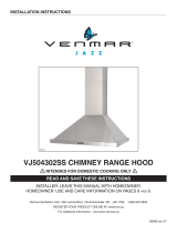
2.3 ALL INSTALLATIONS
The minimum hood distance above cooktop is 24” (30” over a gas range). A
maximum of 30” above cooktop is recommended for best capture of cooking
impurities.
Distances over 30” are at the installer and users discretion providing that ceiling
height and decorative flue length allow it.
HH0246A
3¼” X 10” DUCT
OR 6 ” ROUND DUCT
ROOF CAP
3¼” X 10” DUCT
WALL
C
AP
HOOD
DECORATIVE
FLUE
REFER TO CHART
FOR
DISTANCE ABOVE
COOKING SURFACE
CEILING HEIGHT
MINIMUM HOOD DISTANCE ABOVE
ELECTRIC RANGE COOKTOP
MINIMUM HOOD DISTANCE
ABOVE GAS RANGE COOKTOP
8 FT. 24 IN. 30 IN.
9
FT. 28½ IN. 30 IN.
10 FT.* 28½ IN. 30 IN.
* 10-ft. ceilings require flue extension model no. 63680 (Stainless
steel) or 63685 (Black stainless steel) (sold separately).
Before installation, remove and discard the shipping bracket (in grey) and its retaining
screws. See illustration on the right.
HD0816
SCREW LOCATIONS

4
2. SELECT INSTALLATION TYPE (CONT'D)
Refer to illustrations below to locate duct opening according to discharge type chosen (grey parts to be installed later).
3. REMOVE GREASE FILTERS
Rest the range hood on a table. Remove tapes on
filters. Remove filters from range hood by pushing
them down and tilt, then set aside the filters.
Remove both styrofoam pieces and tape from
under the blower and discard.
3”
2
7
/8”
C
L
9¾”
HK0202A
14
15
/16”
11
15
/16”
17
15
/16”
24”
WIDTH HOOD
30” WIDTH HOOD
36” WIDTH HOOD
3¼”
15/16”
VERTICAL DISCHARGE
12
7
/8”
14
15
/16”
C
L
9¾”
HK0272A
6
7
/16”
11
15
/16”
17
15
/16”
24”
WIDTH HOOD
30” WIDTH HOOD
36” WIDTH HOOD
3¼”
HORIZONTAL DISCHARGE
4. CHOOSE THE OPENING
FOR VERTICAL DISCHARGE OR NON-DUCTED INSTALLATION:
Remove the knockout in order to clear vertical discharge opening (see illustration beside).
HR0122
6” DIA.
C
L
HK0201A
14
15
/16”
11
15
/16”
17
15
/16”
24”
WIDTH HOOD
30” WIDTH HOOD
36” WIDTH HOOD
VERTICAL DISCHARGE OR NON-DUCTED INSTALLATION
HD0811
2
1
VCS500
HD0812
2
1
VCS550

5
5. BLOWER REMOVAL (HORIZONTAL DISCHARGE ONLY)
The VCS500 and VCS550 Series range hoods are factory shipped with the blower mounted for a vertical discharge configuration. For a
horizontal discharge configuration, disassemble the blower from the inner top of the hood (see procedure below). It will be assembled to the
inner back of the hood once the hood is mounted on the wall.
FOR HORIZONTAL DISCHARGE:
From outside the unit, remove the knockout from back of hood (see illustration beside).
HR0123
4. CHOOSE THE OPENING (CONT'D)
2) Using a 5/16” socket, or a Robertson or a Phillips no. 2
screwdriver, remove the 4 blower mounting screws (2 on each
side) from the inner top of the hood. Set the blower and
screws aside.
1) Unplug the blower.
HD0386
RIGHT SIDE MOUNTING
SCREW LOCATIONS
HD0385
LEFT SIDE MOUNTING
SCREW LOCATIONS
HD0817

6
7. WIRING INSTALLATION
WARNING
!
Improper grounding can result in a risk of electric shock. Consult a qualified electrician if the grounding instructions
are not completely understood, or if there is any doubt as to whether the appliance is properly grounded. Do not
use an extension cord. If the power supply cord is too short, have a qualified electrician install an outlet near the
appliance, in accordance with all applicable codes and standards. Turn off electrical power at service entrance
before wiring.
GROUNDING INSTRUCTIONS
This appliance must be grounded. In the event of an electrical short circuit, grounding reduces the risk of electric shock by providing an
escape wire for the electric current. This appliance is equipped with a cord having a grounding wire with a grounding plug. The plug must
be plugged into an outlet that is properly installed and grounded.
Position the outlet within the space covered by the decorative flue. Place the outlet at a
maximum distance of 24” (from where the cord exits from the hood). The center of the outlet
must be positioned at 3½”
from the center of the future hood location (as illustrated beside).
Make sure this does not interfere with a mounting bracket fastening area or with the decorative
flue (where the flue touches the wall).
C
L
C
L
HE0233A
Secure the adapter/damper to the back of the hood using 2 no. 8 x 3/8” screws
(included). Seal the adapter/damper to the hood using metal foil duct tape.
NOTE: The wall ducting must be properly prepared to receive the adapter. Before
performing the installation, make sure the adapter fits easily in the duct.
HJ0129
6. INSTALL ADAPTER/DAMPER (6” ROUND OR 3¼” X 10”)
Mount the 6” round adapter/damper (included in bag) using 4 no. 8 x 3/8” screws (included) or the 3¼” x 10” adapter/damper to the hood
using 2 no. 8 x 3/8” screws (included). Seal the adapter/damper to the hood using metal foil duct tape.
HJ0126
HJ0125
VERTICAL DISCHARGE 3¼” X 10”
H
ORIZONTAL DISCHARGE 3¼” X 10” ONLY
VERTICAL DISCHARGE 6” ROUND AND
NON-DUCTED INSTALLATION ONLY

7
8. INSTALL HOOD MOUNTING BRACKET
Construct wood wall framing that is even with the surface of wall studs.
Wood wall framing must be at least 1/2” thick and 3” high. Fasten wood wall
framing to wall studs for a solid installation.
Make sure that the height of the framing will allow the mounting bracket
to be secured to the framing within the dimensions shown (see illustration
beside).
After wall surface is finished, carefully center and level the hood
mounting bracket over installation location. Secure it to wall framing using
3 no. 8 x 1½” screws.
Using a level, draw a vertical line up to the ceiling starting from the
mounting bracket center.
9. INSTALL UPPER FLUE MOUNTING BRACKET (DUCTED INSTALLATION ONLY)
10. INSTALL THE HOOD
WARNING
!
When cutting or drilling into wall, do not damage electrical
wiring and other hidden utilities.
Center the upper flue mounting bracket with the center line previously
drawn in step 8 and place it flush with the ceiling.
Use the upper flue mounting bracket as a template to mark the position of
its screws.
Drill the 3 screw holes using a 3/16” drill bit.
Insert the included drywall anchors into the drilled holes (1 per hole).
Secure the upper flue bracket to the wall using 3 no. 8 x 3/4” screws.
Ensure that the bracket is tight against the wall.
CAUTION
DO NOT REMOVE the protective plastic film covering the decorative flue (upper & lower) yet.
1. Align the hood and center it above the hood mounting bracket. Gently lower the
hood until it securely engages the bracket.
2. Level the hood.
3. With the hood hanging in place, mark both hole locations on wall (2 embossed
holes on back of hood; see illustration at right).
4. Remove the hood.
5. Drill through both marked holes on wall using a 3/16” drill bit. Insert the included
drywall anchors into the drilled holes (one for each hole).
6. Hang the hood to the wall bracket.
7. Secure the hood to the wall using 2 no. 8 x 3/4” screws and 2 washers.
36
7
/8” = BOTTOM OF HOOD 24” ABOVE COOKTOP
42
7
/8” = BOTTOM OF HOOD 30” ABOVE COOKTOP
SCREW LOCATIONS
HD0377
C
L
CEILING
MOUNTING BRACKET
FLUSH WITH CEILING
WARNING
!
BE CAREFUL when installing the decorative flue and hood, they may have sharp edges.
HOLE LOCATIONS
Ø 3/16” TYP.
HD0810A
SIDE VIEW
HD0813A
WALL STUDS
FRAMING BEHIND DRYWALL
NOTE: ILLUSTRATION ABOVE REPRESENTS HORIZONTAL
EXHAUST CONFIGURATION, BUT IT ALSO APPLIES TO
ALL CONFIGURATIONS.

8
11. REINSTALL BLOWER (HORIZONTAL DISCHARGE ONLY)
1) Position the blower on the inner back of the hood, as shown on the right.
2) Using a 5/16” socket, or a Robertson or a Phillips no. 2 screwdriver and the 4 screws
previously removed, secure the blower to the hood.
NOTE: In order to ease installation, before mounting the blower, prepare the screw holes
by screwing all 4 screws without the blower, then remove and mount the blower.
3) Plug the blower connector back in and plug hood power cord into the outlet.
HD0829
RIGHT SIDE
MOUNTING
SCREW
LOCATIONS
12. PLENUM INSTALLATION (NON-DUCTED INSTALLATION ONLY)
HD1025
Using 4 no. 8 x 3/8” provided screws, assemble the 6” round adapter to the lower plenum plate.
HD1024
A
A
A
Remove the shipping tape retaining the lower and upper plenum plates with the 6” round adapter
together. Carefully align the upper plenum plate central notch with the line traced in step 8 (see
inset at right) and place it flush to the ceiling. Use the plate as a template to mark the position (A)
of its screws.
NOTE: To ease installation, there are many screw configurations: 6 in ceiling and 3 in wall. Only 4
screws are needed to hold the top plenum plate.
Insert the included drywall anchors in the marked holes, then secure the upper plate using
4 no. 8 x 3/4” screws and washers (included with non-duct kit). Make sure the plate is tight against
the wall and ceiling.
HA0135
Assemble the lower plenum plate and 6” round adapter assembly to the upper plate by inserting
both tabs of the top plenum plate to their corresponding slots in lower plenum plate. Secure the
plenum assemby using 2 no. 8-18 x 3/8” screws (included).

9
HJ0131
HJ0130
13. DUCT CONNECTION (VERTICAL DISCHARGE AND NON-DUCTED INSTALLATION ONLY)
VERTICAL DISCHARGE:
Plug hood power cord into the outlet. Slide a 6” round or a 3¼” x 10” metal duct over the adapter/damper on the hood. Use metal foil duct
tape to seal the joint.
NON-DUCTED INSTALLATION:
Plug hood power cord into the outlet.
Slide a 6” round flexible metal duct (included) over the adapter/damper on the hood. Use
metal foil duct tape to seal the joint.
HJ0152
Stretch the flexible metal duct up to the plenum, over the adapter. Use metal foil duct tape
to seal the joint.
HJ0155

10
14. PREPARE DECORATIVE FLUE
HO0271
LOWER FLUE
REAR NOTCH
DUCTED INSTALLATION:
Remove protective plastic film covering the lower flue only.
Peel off both corners at the top of the upper flue (note that upper part has one hole on left and right
sides; see image on the right).
Position the lower flue rear notches down.
Gently slide upper flue inside lower flue.
Both lower and upper flues are included with the hood, but for a 10-foot ceiling, discard the provided
upper flue and use the optional extension flue, part no. 63680 (Stainless steel) or
63685 (Black
stainless steel) (sold separately).
HA0078
LOUVERS
NON-DUCTED INSTALLATION:
Remove protective plastic film covering the lower flue only.
NOTE: Do not use the upper decorative flue included with the hood.
Peel off the plastic film covering both top corners of the upper decorative flue (included with
the non-duct kit).
Position the lower flue rear notches down (the ones with the 45° angle).
Gently slide upper flue inside lower flue, louvers end up.

11
15. INSTALL DECORATIVE FLUE
ALL INSTALLATIONS:
Carefully slide in place decorative flue base (notches end first) in the groove
(shaded part in inset at right) behind the exterior wall of the top of the hood.
DUCTED INSTALLATIONS:
Slide up the upper flue until it is aligned with its mounting bracket. The bracket must be
inside the flue. Secure the upper flue to its bracket using 2 no. 8 x 3/8” included screws for
stainless steel model or 2 no. 8 x 1/2” included black quadrex screws for black stainless
model. See illustration beside.
NOTE: Duct not shown in illustration to ease understanding.
Remove protective plastic film covering the upper flue.
16. REINSTALL MICROMESH (VCS500) OR HYBRID FILTERS (VCS550)
Rest filters springs in range hood inside rear groove. Using finger
cup, tilt up the filters into position. Make sure both screws located
in the front panel edge of the hood are securely engaged in both
filters oval holes (A) after installation.
HD0814
A
HO0140
UPPER FLUE MOUNTING BRACKET
FRONT VIEW
UPPER
FLUE
VCS500
Rest rear filters edge on filter springs in the range hood. Using
finger cup, tilt up the filters into position. Make sure both tabs (B) are
securely engaged in range hood front edge slots after installation.
VCS550
HO0272
HD0815
B
NON-DUCTED INSTALLATION:
Slide the upper flue up to the ceiling. The plenum must be inside the flue. Secure the upper
flue to the plenum sides using 2 no. 8 x 3/8” screws (included) per side for stainless steel
model or 2 no. 8 x 1/2” quadrex black screws (included) per side for black stainless model.
NOTE: Ceiling not shown in illustration to ease understanding.
HA0136
ALL INSTALLATIONS:
Remove protective plastic film covering the upper flue.

12
17. LIGHTING
!
WARNING
Do not touch lamps during or soon after operation. Burns may occur. Cannot be replaced by any other type of light
bulb or LED module.
The lighting of VCS550 Series range hood is produced by two LED modules (included).
The lighting of VCS500 Series range hood is produced by two shielded halogen bulbs (120 V, 50 W, with GU10 base), included.
WARNING
!
Do not touch lamps during or soon after operation. Burns may occur. In order to prevent the risk of personal injury,
only install shielded halogen lamps. Also, never install a cool beam, a dichroic lamp, a lamp not suitable for use in
recessed luminaires or identified for use in enclosed fixtures.
VCS500
VCS550
CAUTION
Do not use suction cup tool on halogen bulbs during or soon after operation; wait until they are cold to use
suction cup tool.
NOTE: The suction cup tool (included with hood) can be used to install and remove light bulbs. Press suction cup tool on bulb and rotate
counterclockwise to remove bulb or clockwise to install bulbs.
1. Install the lamps by placing the bulb leads in the socket.
2. Gently push upwards and turn clockwise until secure.
HR0124
BULB LEADS
SUCTION CUP
TOOL
BULB LEAD GROOVES
(IN SOCKET)
CAUTION
Most GU10 LED replacement bulbs commonly found in the market are not designed for use in a cooking
environment and might not perform as advertised. Their usage with this product is not recommended.

13
18. CARE
WARNING
!
Before servicing or cleaning the unit, switch power off at service panel and lock service panel to prevent power
from being switched on accidentally. When the service disconnecting means cannot be locked, securely fasten a
prominent warning device, such as a tag, to the service panel.
Hood cleaning
Avoid when choosing a detergent:
- Any cleaners that contain bleach will attack stainless steel.
- Any products containing: chloride, fluoride, iodide, bromide will deteriorate surfaces rapidly.
- Any combustible products used for cleaning such as acetone, alcohol, ether, benzol, etc., are highly explosive and should never be
used close to a range.
Do:
• Regularly wash with clean cloth or rag soaked with warm water
and mild phosphate-free soap or liquid dish detergent.
• Always clean in the direction of original polish lines.
• Always rinse well with clear water (2 or 3 times) after cleaning.
Wipe dry completely.
• You may also use a specialized household stainless steel
cleaner
Don’t:
• Use any steel or stainless steel wool or any other scrapers to
remove stubborn dirt.
• Use any harsh or abrasive cleansers.
• Allow dirt to accumulate.
• Let plaster dust or any other construction residues reach the
hood. During construction/renovation, cover the hood to make
sure no dust sticks to stainless steel surface.
19. OPERATION
Always turn ON your hood before you begin cooking in order to establish an air flow in the kitchen. Let the blower run for a few minutes to
clear the air after you turn off the range. This will help keep the whole kitchen cleaner and fresher.
BLOWER SWITCH
I Turns blower on to LOW speed.
• Turns blower OFF.
II Turns blower on to HIGH speed.
LIGHT SWITCH
I Turns light on in LOW intensity.
• Turns light OFF.
II Turns light on to HIGH intensity.
VCS500
Grease Filters
Hybrid and micromesh filters should be cleaned monthly. Remove filters by pushing them towards the back of the hood and flipping them
downward. Use a warm phosphate-free dishwashing detergent solution to clean the filters. Let them dry and reinstall them. Discoloration
of the filters may occur if using phosphate detergents, or as a result of local water conditions−but this will not affect the filter performance.
This discoloration is not covered by the warranty.

14
19. OPERATION (CONT'D)
VCS550
BLOWER BUTTON
When blower is OFF, press this button to turn ON the blower at the last saved speed. If there was no speed saved, the blower will be set
on LOW speed.
NOTE: When LOW speed is activated from OFF, the blower starts on MEDIUM speed for a very short lapse of time, and then resume to
LOW speed.
To change the blower speed, press on this button again until the desired speed is reached (from LOW to MEDIUM to HIGH speed to OFF).
Each time a blower speed is activated, a beep is heard and LED indicators light up to show the corresponding speed chosen (lower LED
for LOW speed, lower and center LEDs for MEDIUM speed and all LEDs for HIGH speed).
When blower is on (no matter the speed level), press and hold this button until the beep sound ends; this will turn off the blower and save
this blower speed to memory.
LIGHT BUTTON
When lights are OFF, press once on this button to turn ON the lights at the last saved setting. If there was no light setting saved, the lights
will be set on LOW intensity. Press another time to set the lights on HIGH intensity. Pressing another time after the HIGH setting will turn
OFF the lights. Each time the lights are turned ON, a beep is heard and LED indicators light up to show the corresponding intensity chosen
(lower LED for LOW and both LEDs for HIGH).
When lights are on (no matter the lighting level), press and hold this button until the beep sound ends; this will turn off the lights and save
the chosen light intensity.
FILTER CLEANING REMINDER
When it is time to clean the hood and filters, the 3 blower button LED indicators will flash slowly for 30 seconds after turning the blower OFF.
This will happen every time the blower is turned OFF until the filter cleaning reminder has been reset. Once the cleaning is done, reset
the filter cleaning reminder indicators by pressing on the blower button for 3 seconds while the 3 blower button LED indicators flash slowly.

15
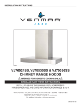
20. WIRING DIAGRAMS
LINE
NEUTRAL
GROUND
120 V AC
CONTROL BOARD
J2
POWER
MOTOR
J6
OVERRIDE
5
4
32
1
6
J4
LED
J1
TRANSFORMER
RED
LED
LED
BLK
5
4
3
2
1
5
4
3
2
1
7
6
2
3
4
1
J10
INTERFACE
1
2
3
4
5
6
7
8
USER INTERFACE
MOUNTED TO J10
ON BACK OF
CONTROL BOARD
RED
FAN MOTOR
BRN
GRY
BLU
WHT
WHT
2
6
5
1
3
4
WHT
BLK
RED (LOW)
ORG (MEDIUM
)
BLK (HIGH)
BLK
WHT
WHT
BLU
BLU
RED
RED
BLK
BLK BLACK
BLU BLUE
BRN BROWN
GRY GREY
ORG ORANGE
RED RED
WHT WHITE
COLOR CODE
HE0236A
BLK
ORG
LINE
NEUTRAL
GROUND
120 V AC
RED
FAN MOTOR
BLU
ORA
YEL (LOW)
BLK
LIGHTS SWITCH
MOTOR SWITCH
RED (LOW)
BLK
WHT
WHT
BLK (HIGH)
BLU (HIGH)
BLK
WHT
2
6
5
1
3
4
BLK
WHT
BRN
GRY
HE0257A
BLK BLACK
BLU BLUE
BRN BROWN
GRY GREY
ORG ORANGE
RED RED
WHT WHITE
YEL YELLOW
COLOR CODE
BLK
VCS500
VCS550

16
21. WARRANTY
WARRANTY
VENMAR VENTILATION FIVE-YEAR WARRANTY
Venmar Ventilation ULC warrants to the original consumer purchaser of the Venmar Chef VCS500 and VCS550 Series range hood that
such product will be free from defects in materials or workmanship for a period of five (5) years from date of original purchase except
for LED modules which is covered for a period of three (3) years. This warranty includes in-home service for the first year and workshop
service for the four (4) remaining years.
THERE ARE NO OTHER WARRANTIES, EXPRESS OR IMPLIED, INCLUDING, BUT NOT LIMITED TO, IMPLIED WARRANTIES
OF MERCHANTABILITY OR FITNESS FOR A PARTICULAR PURPOSE. VENMAR VENTILATION ULC WILL NOT BE HELD
RESPONSIBLE FOR ANY CLAIMS OVER THE ORIGINAL PURCHASE PRICE OF A VENMAR VCS500 AND VCS550 SERIES
RANGE HOOD NOR HELD RESPONSIBLE FOR SUBSEQUENT DAMAGE OR INCIDENT.
During the period stated above, Venmar Ventilation ULC will, at its option, repair or replace without charge any product or part which is
found to be defective under normal use and service. THIS WARRANTY DOES NOT EXTEND TO ANY LIGHT BULBS AND FILTERS.
This warranty does not cover (a) normal maintenance and service, (b) any products or parts which have been subject to misuse,
negligence, accident, improper maintenance or repair made by other than Venmar Ventilation ULC, or c) faulty installation or installation
contrary to recommended installation instructions.
Warranty service is to be completed by an authorized Service Center designated by Venmar Ventilation ULC. Where applicable,
in-home service will be made available only in areas where a contracted service provider offers service. If in-home service is not
available, the product will be repaired or replaced, at Venmar’s discretion, by the nearest authorized service provider. The unit removal
and reinstallation works are under the customer responsibility, and Venmar cannot be charged for them.
The duration of any implied warranty is limited to the 5-year period as specified for the express warranty. Some provinces do not allow
limitation on how long an implied warranty lasts, so the above limitation may not apply to you.
VENMAR VENTILATION ULC'S OBLIGATION TO REPAIR OR REPLACE, AT VENMAR VENTILATION ULC’S OPTION, SHALL BE THE
PURCHASER’S SOLE AND EXCLUSIVE REMEDY UNDER THIS WARRANTY. VENMAR VENTILATION ULC SHALL NOT BE LIABLE
FOR INCIDENTAL, CONSEQUENTIAL OR SPECIAL DAMAGES ARISING OUT OF OR IN CONNECTION WITH PRODUCT USE OR
PERFORMANCE. SOME PROVINCES DO NOT ALLOW THE EXCLUSION OR LIMITATION OF INCIDENTAL OR CONSEQUENTIAL
DAMAGES, SO THE ABOVE LIMITATION OR EXCLUSION MAY NOT APPLY TO YOU.
This warranty gives you specific legal rights, and you may also have other rights, which vary from province to another. This warranty
supersedes all prior warranties.
To contact Venmar Ventilation ULC warranty service call 1-800-567-3855 in Canada. In order to qualify for a warranty claim, the owner of
a Venmar Chef Series range hood must have the model and serial number along with a proof of the original purchase date. At the time
of requesting service, describe the nature of any defect in the product or part.
Venmar Ventilation ULC, 550 Lemire Blvd., Drummondville, QC J2C 7W9 (1-800-567-3855)
www.venmar.ca

17
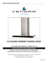
22. SERVICE PARTS
REPLACEMENT PARTS AND REPAIRS
In order to ensure your unit remains in good working condition, you must use
Venmar Ventilation ULC genuine replacement parts only. Venmar Ventilation
ULC genuine replacement parts are specially designed for each unit and are
manufactured to comply with all the applicable certification standards and
maintain a high standard of safety. Any third party replacement part used
may cause serious damage and drastically reduce the performance level
of your unit, which will result in premature failing. Venmar Ventilation ULC
recommends to contact a certified service depot for all replacement parts
and repairs.
VCS500
* NOT SHOWN
ITEM
N
O.
P
ART NO.DESCRIPTION
QTY. (HOOD WIDTH)
24”
S
TAINLESS
30”
STAINLESS
36”
STAINLESS
1 63673 UPPER FLUE MOUNTING BRACKET 111
2 SV63663 UPPER DECORATIVE FLUE, STAINLESS 111
3 SV63662 LOWER DECORATIVE FLUE, STAINLESS 111
4 13296 3¼” X 10” ADAPTER/DAMPER 111
5 SV08487 6” ROUND ADAPTER/DAMPER 111
6 SV08582
INTERNAL BLOWER
(INCLUDING CAPACITOR)
111
7 SV05921
SHIELDED HALOGEN BULBS
120 V, 50 W, GU10 TYPE
222
8 09983 SUCTION CUP 111
9
63677 MICROMESH FILTERS (THE PAIR)1
14131 MICROMESH FILTERS (THE PAIR)11
10 63678 R
OCKER SWITCH (2) 1 1 1
11 09014 HOOD MOUNTING BRACKET 111
* 22745 INSTALLATION GUIDE 111
* 09027
PARTS BAG :
5 NO. 8 X 1½” COUNTERSUNK SCREWS,
8 NO. 8 X 3/4” SCREWS
6 NO. 8 X 3/8” SCREWS
6 DRYWALL ANCHORS, 3 WASHERS,
2 NO. 8 X 1/2” SCREWS,
2 NEOPRENE PIECES, 2 NO. 8 X 1/2”
QUADREX BLACK SCREWS.
111
HL0307
B
C
D
H
L
I
F
E
K
J
G
KEY
NO.
PART NO.DESCRIPTION QTY.
12 SV63628
NON-DUCT KIT UPPER DECORATIVE FLUE CHIMNEY,
STAINLESS STEEL
1
13 SV22756 6” ROUND METAL FLEXIBLE DUCT 1
14 SV63626 UPPER PLENUM PLATE 1
15 SV63627 LOWER PLENUM PLATE 1
16 SV08487WD 6” ROUND ADAPTER 1
17 SV22758 CHARCOAL FILTER (PAIR) (INCLUDING ITEM 18) 1
18 S99527587 CHARCOAL FILTER CLIP (SET OF 4) 1
* SV05803
PARTS BAG:
10 NO. 8-18 X 3/8” SCREWS,
4 NO. 8 X 1/2” BLACK SCREWS,
9 NO. 8-18 X 3/4” SCREWS, 4 WASHERS,
9 DRYWALL ANCHORS, 6 NO. 6 X 1/2” SCREWS.
1
* NOT SHOWN.
NON-DUCT KIT MODEL HRKMSS
HL0384
M
N
O
Q
P
S
R

18
REPLACEMENT PARTS AND REPAIRS
In order to ensure your unit remains in good working condition, you must use Venmar
Ventilation ULC genuine replacement parts only. Venmar Ventilation ULC genuine
replacement parts are specially designed for each unit and are manufactured to
comply with all the applicable certification standards and maintain a high standard
of safety. Any third party replacement part used may cause serious damage and
drastically reduce the performance level of your unit, which will result in premature
failing. Venmar Ventilation ULC recommends contacting a certified service depot for
all replacement parts and repairs.
21. SERVICE PARTS (CONT'D)
VCS550
ITEM
NO.
PART NO.DESCRIPTION
QTY. (HOOD WIDTH)
30”
S
TAINLESS
36”
STAINLESS
30”
BLACK
STAINLESS
36”
BLACK
STAINLESS
1 63673 UPPER FLUE MOUNTING BRACKET 1111
2
SV63663 UPPER DECORATIVE FLUE, STAINLESS 11
SV63665
UPPER DECORATIVE FLUE,
BLACK STAINLESS
11
3
SV63662 LOWER DECORATIVE FLUE, STAINLESS 11
SV63664
LOWER DECORATIVE FLUE,
BLACK STAINLESS
11
4 13296 3¼” X 10” ADAPTER/DAMPER 1111
5 SV08487 6” ROUND ADAPTER/DAMPER 1111
6 97020187 LED MODULE (1) 2222
7 99271569 TRANSFORMER 1111
8 SV08582
INTERNAL BLOWER
(INCLUDING CAPACITOR)
1111
9 62053
HYBRID FILTER
15.875” X 14” X 0.5” (1)
2222
10
63681
CAPACITIVE CONTROL
2 BUTTONS (STAINLESS)
11
63682
C
APACITIVE CONTROL
2 BUTTONS (BLACK)
11
11 09014 HOOD MOUNTING BRACKET 1111
* 22745 INSTALLATION GUIDE 1111
* 09027
PARTS BAG:
5 NO. 8 X 1½” COUNTERSUNK SCREWS,
8 NO. 8 X 3/4” SCREWS,
6 NO. 8 X 3/8” SCREWS,
6 DRYWALL ANCHORS, 3 WASHERS,
2 NO. 8 X 1/2” SCREWS,
2 NEOPRENE PIECES, 2 NO. 8 X 1/2”
QUADREX BLACK SCREWS
1111
* NOT SHOWN
HL0283
B
C
D
L
I
G
H
K
J
E
F
KEY
NO.
PART NO.DESCRIPTION QTY.
12
SV63628
NON-DUCT KIT UPPER DECORATIVE FLUE CHIMNEY,
STAINLESS STEEL
1
SV63629
N
ON-DUCT KIT UPPER DECORATIVE FLUE CHIMNEY,
BLACK STAINLESS STEEL
13 SV22756 6” ROUND METAL FLEXIBLE DUCT 1
14 SV63626 UPPER PLENUM PLATE 1
15 SV63627 LOWER PLENUM PLATE 1
16 SV08487WD 6”
ROUND ADAPTER 1
17 SV22759 C
HARCOAL FILTER (PAIR)1
18 SV22757 CHARCOAL FILTER CLIP (SET OF 4) 1
* SV05803
PARTS BAG:
10 NO. 8-18 X 3/8” SCREWS,
4 NO. 8 X 1/2” BLACK SCREWS,
9 NO. 8-18 X 3/4” SCREWS, 4 WASHERS,
9 DRYWALL ANCHORS, 6 NO. 6 X 1/2” SCREWS.
1
* NOT SHOWN.
NON-DUCT KIT MODELS HRKBSS AND HRKBBLS
HL0385
M
N
O
Q
P
S
R
/