ProCom Heating SSFBD28T User manual
- Category
- Fireplaces
- Type
- User manual

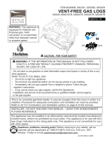
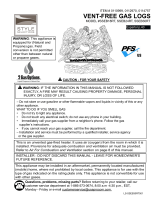
WARNING: IF THE INFORMATION IN THIS MANUAL IS NOT FOLLOWED
EXACTLY, A FIRE MAY RESULT CAUSING PROPERTY DAMAGE, PERSONAL
INJURY, OR LOSS OF LIFE.
– Do not store or use gasoline or other ammable vapors and liquids in vicinity of
this or any other appliance.
WHAT TO DO IF YOU SMELL GAS
• Do not try to light any appliance.
• Do not touch any electrical switch; do not use any phone in your building.
• Immediately call your gas supplier from a neighbor’s phone. Follow the gas
supplier’s instructions.
• If you cannot reach your gas supplier, call the re department.
– Installation and service must be performed by a qualied installer, service agency
or the gas supplier.
This appliance may be installed in an aftermarket, permanently located manufactured
(mobile) home, where not prohibited by local codes. This appliance is for use with the
type of gas indicated on the rating plate only. This appliance is not convertible for use
with other gases.
This is an unvented gas-red heater. It uses air (oxygen) from the room in which it is
installed. Provisions for adequate combustion and ventilation air must be provided.
Refer to Air For Combustion and Ventilation section on page 8 of this manual.
INSTALLER : DO NOT DISCARD THIS MANUAL - LEAVE FOR HOMEOWNER'S
FUTURE REFERENCE.
Questions, problems, missing parts? Before returning to your retailer, contact
our customer service department at 1-866-573-0674, 8:00 a.m - 4:30 p.m.,
EST, Monday - Friday or e-mail [email protected].
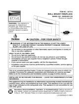
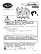
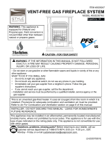
WARNING: This appliance
is equipped for (Natural and
Propane) gas. Field conversion is
not permitted other than between
natural or propane gases.
LS-FBD28D654-1002
ITEM #0030334
VENT-FREE GAS FIREPLACE INSERT
MODEL #SSFBD28T
Español p. 32
CAUTION - FOR YOUR SAFETY

2
TABLE OF CONTENTS
Safety Information.........................................................................................................................3
Product Features...........................................................................................................................6
Air For Combustion and Ventilation...............................................................................................8
Installation ...................................................................................................................................11
Installing Logs..............................................................................................................................19
Operation.....................................................................................................................................20
Care and Maintenance................................................................................................................24
Troubleshooting...........................................................................................................................26
Replacement Parts......................................................................................................................29
WARNING: Read the installation & operation instructions before using this
appliance.
IMPORTANT: Read instructions and warnings carefully before starting installation.
Failure to follow these instructions may result in a possible re
hazard and will void the warranty.
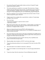
PRODUCT SPECIFICATIONS
ITEM # 0030334 VENT FREE GAS FIREPLACE INSERT
Input Rating 26,000 BTU/Hr 26,000 BTU/Hr
Gas Type Natural LP/Propane
Ignition Piezo/Automatic Piezo/Automatic
Manifold Pressure 4 in. W.C. 9 in. W.C.
Inlet Gas Pressure (*For purpose of inlet adjustment)
Maximum 10.5 in. 14 in.
Minimum 5 in. 11 in.
Dimension, inches (H x W x D)
Heater 28.74 in. x 23.9 in. x 12 in.
Carton 31.2 in. x 27.1 in. x 14.84 in.
Weight, lbs.
Stove 48.5
Shipping 56.6

3
SAFETY INFORMATION
IMPORTANT: Read this owner’s manual carefully and completely before trying to assemble,
operate, or service this heater. Improper use of this heater can cause serious injury or death from
burns, re, explosion, electrical shock, and carbon monoxide poisoning.
Only a qualied installer, service agent, or local gas supplier may install and service this product.
WARNING: Do not store or use gasoline or other ammable vapors or liquids in the
vicinity of this or any other appliance.
WARNING: This appliance is for use with only the type of gas indicated on the rating
plate. This appliance is not convertible for use with other gases.
CARBON MONOXIDE POISONING: Early signs of carbon monoxide poisoning resemble the u
with headaches, dizziness, or nausea. If you have these signs, the heater may not be working
properly. Get fresh air immediately! Have heater serviced. Some people are more affected
by carbon monoxide than others. These include pregnant women, people with heart or lung
disease, people who are anemic, those under the inuence of alcohol, and those living in high
altitudes.
NATURAL AND PROPANE/LP GAS: Natural and Propane/LP gases are odorless. An odor-
making agent is added to the gas. The odor helps you detect a gas leak. However, the odor
added to the gas can fade. Gas may be present even though no odor exists. Make certain you
read and understand all warnings. Keep this manual for reference. It is your guide to operating
this heater safely.
WARNING: Any change to this replace or its controls can be dangerous.
WARNING: Do not allow fans to blow directly into replace. Avoid any drafts that alter
burner ame patterns.
WARNING: Do not use a blower insert, heat exchange insert or other accessory not
approved for use with this heater.
Due to high temperatures, the appliance should be located out of trafc and away from furniture
and draperies. Do not place clothing or other ammable material on or near the appliance. Never
place any objects in the heater. Heater becomes very hot when running heater. Keep children and
adults away from hot surfaces to avoid burns or clothing ignition. Fireplace will remain hot for a
time after shutdown. Allow surfaces to cool before touching. Carefully supervise young children
when they are in the room with the heater.
You must operate this heater with screen in place. Keep the heater area clear and free from
combustible materials, gasoline, and other ammable vapors and liquids.

4
1. Do not place Propane/LP supply tank(s) inside any structure. Propane/LP supply
tank(s) must be placed outdoors.
2. This heater needs fresh air ventilation to run properly. This heater has an Oxygen
Depletion Sensing (ODS) safety shut-off system. The ODS shuts down the heater if
not enough fresh air is available. See Air for Combustion and Ventilation, pages 8
through 10. If heater keeps shutting off, see Troubleshooting, pages 26 through 28.
3. Keep all air openings in front and bottom of heater clear and free of debris. This will
ensure enough air for proper combustion.
4. If heater shuts off, do not relight until you provide fresh, outside air. If heater keeps
shutting off, have it serviced.
5. Do not run heater:
• Where ammable liquids or vapors are used or stored.
• Under dusty conditions.
6. Before using furniture polish, wax, carpet cleaner, or similar products, turn heater off. If
heated, the vapors from these products may create a white powder residue within
burner box or on adjacent walls or furniture.
7. Always run heater with control knob at PILOT or ON locked positions.
Never set control knob between locked positions. Poor combustion and higher levels of
carbon monoxide may result.
8. Do not use heater if any part has been under water. Immediately call a qualied service
technician to inspect the room heater and to replace any part of the control system and
any gas control which has been under water.
9. Turn off and unplug heater and let cool before servicing. Only a qualied service
person should service and repair heater.
10. Operating heater above elevations of 4,500 ft. could cause pilot outage.
11. To prevent performance problems, do not use propane/LP fuel tank of less than 100 lb.
capacity.
12. This heater should not be installed in a bedroom or bathroom.
13. Do not use this heater as a wood-burning heater. Use only the logs provided with the
heater.
14. To prevent sooting, follow the instructions in Care and Maintenance (page 24).

5
15. Do not add extra logs or ornaments such as pine cones, vermiculite, or rock wool.
Using these added items can cause sooting. Do not add lava rock around base. Rock
and debris could fall into the control area of heater. After servicing, always replace
screen before operating heater.
16. This heater is designed to be smokeless. If logs ever appear to smoke, turn off heater
and call a qualied service person. Note: During initial operation, slight smoking could
occur due to log curing and the heater burning manufacturing residues.
QUALIFIED INSTALLING AGENCY
Only a qualied agency should perform installation and replacement of gas piping, gas
utilization equipment or accessories, and repair and servicing of equipment. The term
“qualied agency” means any individual, rm, corporation, or company that either in
person or through a representative is engaged in and is responsible for:
a) Installing, testing, or replacing gas piping or
b) Connecting, installing, testing, repairing, or servicing equipment; that is experienced
in such work; that is familiar with all precautions required; and that has complied with
all the requirement of the authority having jurisdiction.

6
SAFETY PILOT
This heater has a pilot with an Oxygen Depletion Sensing (ODS) safety shutoff system.
The ODS/pilot shuts off the heater if there is not enough fresh air.
PIEZO IGNITION SYSTEM
This heater is equipped with an electronic piezo control system. This system requires
AAA batteries (provided).
THERMOSTAT HEAT CONTROL
The control automatically cycles the burner on and off to maintain a desired room
temperature. See page 21.
2 GAS OPTIONS CAPABLE
Your heater is equipped to operate on either propane or natural gas. The heater is
shipped from the factory ready for connecting to propane. The heater can easily be
changed to natural gas by having your qualied installer follow the instructions on page
16 and the markings on the heater.
State of Massachusetts: The installation must be made by a licensed plumber or
gas tter in the Commonwealth of Massachusetts. Sellers of unvented propane or
natural gas-red supplemental room heaters shall provide to each purchaser a copy
of 527 CMR 30 upon sale of the unit.
In the State of Massachusetts, unvented propane or natural gas-red space heaters
shall be prohibited in bedrooms and bathrooms.
In the State of Massachusetts the gas cock must be a T-handle type. The State
of Massachusetts requires that a exible appliance connector cannot exceed
three feet in length.
Install and use heater with care. Follow all codes. In the absence of local codes, use the latest
edition of The National Fuel Gas Code, ANSI Z223.1, also known as NFPA 54*.
*Available from:
American National Standard Institute, Inc National Fire Protection Association, Inc.
1430 Broadway 1 Batterymarch Park
New York, NY 10018 Quincy, MA 02269-9101
This heater is designed for vent-free operation. State and local codes in some areas prohibit the
use of vent-free heaters.
LOCAL CODES
PRODUCT FEATURES

7
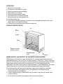
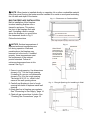
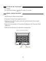
1. Remove top inner pack.
2. Tilt carton so that heater is upright.
3. Remove protective side packaging.
4. Slide heater out of carton.
5. Remove protective plastic wrap.
6. Hold the screen, lift, and pull forward.
7. Remove log set by cutting plastic ties.
8. Carefully unwrap log.
9. Check for any shipping damage. If heater or log is damaged, promptly inform your
dealer where you bought the heater.
10. Remove four screws and two bottoms of angle iron.
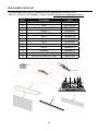
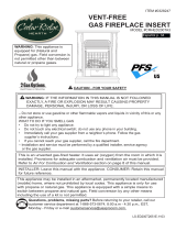
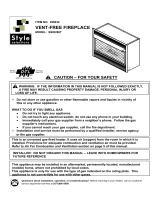
PRODUCT IDENTIFICATION
WATER VAPOR: A BY-PRODUCT OF UNVENTED ROOM HEATERS
Water vapor is a by-product of gas combustion. An unvented room heater produces
approximately one (1) ounce (30 mL) of water for every 1,000 BTUs (.3 kw) of gas input
per hour. An unvented room heater is recommended as a supplemental heater (a room)
rather than a primary heat source (an entire house). In most supplemental heat
applications, the water vapor does not create a problem. In most applications, the water
vapor enhances the low humidity atmosphere experienced during cold weather.
The following steps will help ensure that water vapor does not become a problem:
1. Be sure the heater is the proper size for the application, including adequate
combustion air and circulation air.
2. If there is high humidity, a dehumidier may be used to help lower the water vapor
content of the air.
3. Do not use an unvented room heater as the primary heat source.
Fig. 1
UNPACKING
Hood
Screen
Logs
Heater Controls
(Behind Panel)
Shipping Bracket
Front
Screw

8
AIR FOR COMBUSTION AND VENTILATION
WARNING: This heater should not be installed in a conned space or unusually tight
construction unless provisions are provided for adequate combustion and ventilation
air. Read the following instructions to ensure proper fresh air for this and other fuel burning
appliances in your home.
PRODUCING ADEQUATE VENTILATION
This heater shall not be installed in a room or space unless the required volume of indoor
combustion air is provided by the method described in the NATIONAL FUEL GAS CODE,
ANSI Z223.1/NFPA 54, the INTERNATIONAL FUEL GAS CODE, or applicable local codes.
The following are excerpts from National Fuel Gas Code, NFPA 54/ANSI Z223.1,Section
5.3, Air for Combustion and Ventilation. All spaces in homes fall into one of the three
following ventilation classications:
1. Unusually Tight Construction
2. Unconned Space
3. Conned Space
The information on pages 8 through 9 will help you classify your space and provide
adequate ventilation.
Conned and Unconned Space
The National Fuel Gas Code, ANS Z 223.1 denes a conned space as a space whose
volume is less than 50 cu. ft. per 1,000 BTU/hr (4.8 m^3 per kw) of the aggregate input
rating of all appliances installed in that space and an unconned space as a space
whose volume is not less than 50 cu. ft. per 1,000 BTU/hr (4.8 m^3 per kw) of the
aggregate input rating of all appliances installed in that space. Rooms connecting
directly with the space in which the appliances are installed*, through openings not
furnished with doors, are considered a part of the unconned space.
This heater shall not be installed in a conned space or unusually tight construction
unless provisions are provided for adequate combustion and ventilation air.
* Adjoining rooms are connecting only if there are door-less passageways or
ventilation grills between them
Unusually Tight Construction
The air that leaks around doors and windows may provide enough fresh air for
combustion and ventilation. However, in buildings of unusually tight construction, you
must provide additional fresh air.
Unusually tight construction is dened as construction where:
a) walls and ceilings exposed to the outside atmosphere have a continuous water vapor
retarder with a rating of one perm (6x10
-11
kg per pa-sec-m
2
) or less with openings
gasket or sealed and
b) weather stripping has been added on windows that can be opened and on doors and
c) caulking or sealants are applied to areas such as joints around window and door frames,
between sole plates and oors, between wall-ceiling joints, between wall panels, at
penetrations for plumbing, electrical, and gas lines, and at other openings.
If your home meets all of the three criteria above, you must provide additional fresh air.
See “Ventilation Air From Outdoors” (page 10). If your home does not meet all of the
three criteria above, proceed to “Determining Fresh-Air Flow For Heater Location”.

9
DETERMINING FRESH-AIR FLOW FOR HEATER LOCATION
Determining if You Have a Conned or Unconned Space
Use this worksheet to determine if you have a conned or unconned space.
Space: Includes the room in which you will install heater plus any adjoining rooms with
door-less passageways or ventilation grills between the rooms.
1. Determine the volume of the space Length × Width × Height = cu. ft. (volume of space)
Example: Space size 20 ft. (length) × 16 ft.(width) × 8 ft. (ceiling height) = 2560 cu. ft.
(volume of space)
If additional ventilation to adjoining room is supplied with grills or openings, add the
volume of these rooms to the total volume of the space.
2. Divide the space volume by 50 cu. ft. to determine the maximum BTU/hr the space
can support.
_______ (volume of space) ÷ 50 cu. ft.= (Maximum BTU/hr the space can support)
Example: 2560 cu. ft. (volume of space) ÷ 50 cu. ft. = 51.2 or 51,200 (maximum
BTU/hr the space can support)
3. Add the BTU/hr of all fuel burning appliances in the space.
Vent-free heater ________ BTU/hr
Gas water heater* _______BTU/hr
Gas furnace ___________ BTU/hr
Vented gas heater _______BTU/hr Example:
Gas heater logs ________ BTU/hr Gas water heater 30,000 BTU/hr
Other gas appliances*+ ___BTU/hr Vent-free heater + 26,000 BTU/hr
Total =________________ BTU/hr Total = 56,000 BTU/hr
*Do not include direct-vent gas appliances. Direct-vent draws combustion air from the
outdoors and vents to the outdoors.
4. Compare the maximum BTU/hr the space can support with the actual amount of BTU/hr
used.
_______ BTU/hr (maximum the space can support)
_______ BTU/hr (actual amount of BTU/hr used).
Example : 51,200 BTU/hr (maximum the space can support)
56,000 BTU/hr (actual amount of BTU/hr used)
The space in the above example is a conned space because the actual BTU/hr used is
more than the maximum BTU/hr the space can support.
You must provide additional fresh air. Your options are as follows:
a) Rework worksheet, adding the space of an adjoining room. If the extra space
provides an unconned space, remove door to adjoining room or add ventilation
grills between rooms. See “Ventilation Air From Inside Building,” page 10.
b) Vent room directly to the outdoors. See “Ventilation Air From Outdoors”, page 10.
c) Install a lower BTU/hr heater if lower BTU/hr size makes room unconned. If the
actual BTU/hr used is less than the maximum BTU/hr the space can support, the
space is an unconned space. You will need no additional fresh air ventilation.

10
WARNING: If the area in which the heater may be operated is smaller than that dened as
an unconned space or if the building is of unusually tight construction, provide adequate
combustion and ventilation air by one of the methods described in the National Fuel Gas
Code, ANS Z223.1, Section 5.3 or applicable local codes.
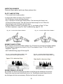
Ventilation Air From Outdoors
Provide extra fresh air by using ventilation
grills or duct. You must provide two
permanent openings: one within 12 in. of
the ceiling and one within 12 in. of the oor.
Connect these items directly to the outdoors
or spaces open to the outdoors. These
spaces include attics and crawl spaces.
Follow the National Fuel Gas Code NFPA
54/ANS Z223.1. Air for Combustion and
Ventilation for required size
of ventilation grills or ducts.
Ventilation Air From Inside Building
This fresh air would come from adjoining
unconned space. When ventilating to an
adjoining unconned space, you must
provide two permanent openings: one
within 12 in. of the wall connecting
the two spaces (see options 1 and 2,
Fig. 2). You can also remove door into
adjoining room (see option 3, Fig. 2).
Follow the National Fuel Gas Code
NFPA 54/ANS Z223.1. Air for Combustion
and Ventilation for required size of
ventilation grills or ducts.
IMPORTANT: Do not provide openings
for inlet or outlet air into attic if attic has a
thermostat-controlled power vent. Heated
air entering the attic will activate the
power vent. Rework worksheet, adding the
space of the adjoining unconned space.
The combined spaces must have enough
fresh air to supply all appliances in both
spaces.
Fig. 2 - Ventilation Air from Inside Building
Fig. 3 - Ventilation Air from Outdoors
WARNING: If the area in which the heater may be operated does not meet the required
volume for indoor combustion air, combustion and ventilation air shall be provided by one
of the methods described in the NATIONAL FUEL GAS CODE, ANSI Z223.1/NFPA 54, the
INTERNATIONAL FUEL GAS CODE, or applicable local codes.
Ventilation
Grills
Into Adjoining
Room,
Option 1
Or
Remove
Door
Into
Adjoining
Room,
Option 3
Ventilation Grills
Into adjoining Room,
Option 2
Outlet
Air
Ventilated
Attic
To Attic
To
Crawl
Space
Outlet
Air
Inlet
Air
Inlet Air
Ventilated
Crawl Space

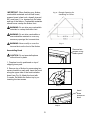
11
Fig. 4 - Minimum Clearance to
Wall and Ceiling
INSTALLATION
NOTICE: This heater is intended for use as supplemental heat. Use this heater along
with your primary heating system. Do not install this heater as your primary heat source.
If you have a central heating system, you may run system’s circulating blower while
using heater. This will help circulate the heat throughout the house.
WARNING: A qualied technician must install heater. Follow all local codes.
WARNING: Never install the heater:
• in a bedroom or bathroom
• in a recreational vehicle
• where curtains, furniture, clothing, or other ammable objects are less than 42
in. from the front, top or sides of the heater.
• in high trafc areas
• in windy or drafty areas
CAUTION: This heater creates warm air currents. These currents move heat to wall
surfaces next to heater. Installing heater next to vinyl or cloth wall coverings or
operating heater where impurities (such as tobacco smoke, aromatic candles, cleaning
uids, oil or kerosene lamps, etc.) in the air exist, may cause walls to discolor.
WARNING: Maintain the minimum clearances. If you can, provide greater clearances
from oor, ceiling and adjoining side and back walls.
IMPORTANT: Vent-free heaters add moisture to the air. Although this is benecial,
installing heater in rooms without enough ventilation air may cause mildew to form from
too much moisture. See Air for Combustion and Ventilation, pages 8 through 10.
CHECK GAS TYPE
Use only the type of gas indicated on the plate. If your gas supply cannot meet that
requirement, do not install heater.
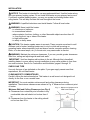
CLEARANCES TO COMBUSTIBLES
Carefully follow the instructions below. This heater is a wall mount unit designed to sit
directly on the oor or on a mantel base.
IMPORTANT: You must maintain minimum wall and ceiling clearances during
installation. The minimum clearances are shown in Fig. 4. Measure from outermost point
of heater.
Minimum Wall and Ceiling Clearances (see Fig. 4)
A. Clearances from outermost point of heater to any
combustible side wall should not be less than 6
in.
B. Clearances from the heater to the ceiling should
not be less than 36 in.
36 in
Minimum
Ceiling
6 in
Minimum
Front View
Side Wall Side Wall
6 in
Minimum

12
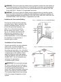
BUILT-IN FIREPLACE INSTALLATION
Built-in installation of this replace
involves installing replace into a
framed-in enclosure. This makes
the front of the replace ush with
wall. If installing a built-in mantel
above the replace, you must follow
the clearances shown in Fig. 5.
Follow the instructions
NOTICE: Surface temperatures of
adjacent walls and mantels become
hot during operation. Walls and
mantels above the replace may
become hot to the touch. If installed
properly, these temperatures meet
the requirement of the national
product standard. Follow all
minimum clearances shown in this
manual. See Fig. 6.
1. Frame in rough opening. Use dimensions
shown in Fig. 7 for the rough opening.
If installing in a corner, use dimensions
shown in Fig. 8 for the rough opening.
The height is 26 1/2 -in., which is the
same as the wall opening above.
2. Carefully set replace in front of rough
opening with back of replace inside wall
opening.
3. Attach gas line to replace gas regulator.
See "Connecting to Gas Supply," page 14.
4. Check all gas connections for leaks. See
“Checking Gas Connections,” page 18.
Fig. 7 - Rough Opening for Installing in Wall
Fig. 5 - Clearance to Combustibles
Fig. 6
NOTE: When heater is installed directly on carpeting, tile or other combustible material,
other than wood ooring, the heater must be installed on a metal or wood panel extending
the full width and depth of the heater.
Note All vertical
measurements are
from top of replace
opening to bottom
of mantel shelf. All
measurements are
in inches.
Side of
Firebox
Mantel Shelf
Note: Height of replace opening on facia to 23 ¼ inches
3/4 in. Clearance to facia
1
3
/
8
in. Clearance to Sides, Back and Top

13
Fig. 8 - Rough Opening for
Installing in Corner
IMPORTANT: When nishing your rebox,
combustible materials such as wall board,
gypsum board, sheet rock, drywall, plywood,
etc, must have ½ -in. clearance to the sides
and top of the rebox. Combustible materials
should never overlap the rebox front.
WARNING: Do not allow any combustible
materials to overlap the rebox front.
WARNING: Do not allow combustible or
noncombustible materials to cover any
necessary openings like louvered slots.
WARNING: Never modify or cover the
louvered slots on the front of the rebox.
Step 1
Step 3
Step 2
Fig. 9
Remove two
screws on top
rebox panel
Insert
three
screws on
hood
Assembling Hood
CAUTION: Do not operate replace
without hood in place.
1. Fireplace hood is positioned on top of
shipping inner pack.
2. Remove top of rebox by unscrewing two
screws located on each end. Insert the hood
along the upper side of the heat insulation
board (see Fig. 9). Attach the hood with
3 screws. Re-attach the rebox top by re-
inserting the two screws.

14
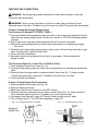
CONNECTING TO GAS SUPPLY
WARNING: A qualied technician must connect heater to gas supply. Follow all local
codes.
WARNING: This appliance requires a 3/8 in. NPT inlet connection to pressure regulator
(see Fig. 10).
CAUTION: Never connect heater directly to the gas supply. This heater requires an external
regulator (not supplied). The external regulator between the gas supply and heater must be
installed. Gas supplier provides external regulator for natural gas.
INSTALLATION ITEMS NEEDED
Before installing heater, make sure you have the items listed below.
• piping (check local codes) sealant
• (resistant to propane/LP gas)
• equipment shutoff valve*
• test gauge connection**
• sediment trap
• tee joint
• pipe wrench
• exible gas hose (check local code)
A CSA design-certied equipment shutoff valve with 1/8 in. NPT tap is an acceptable alternative
to test gauge connection. Purchase the optional CSA design certied equipment shutoff valve
from your dealer.
WARNING: Never connect heater to private (non-utility) gas wells. This gas is commonly
known as wellhead gas.
The installer must supply an external regulator for liquid propane. The external regulator is
provided by the gas supplier for natural gas. The external regulator will reduce incoming
gas pressure. You must reduce incoming gas pressure to between 11 and 14 in. of
water column for propane and between 5 and 10.5 in. of water column for natural gas.
If you do not reduce incoming gas pressure, heater regulator damage could occur. Install
external regulator with the vent pointing down as shown in Fig. 11. Pointing the vent
down protects it from freezing rain or sleet.
Fig. 10 - Gas Regulator Location and Gas
Line Access Into Stove Cabinet
Fig. 11 - External Regulator With Vent
Pointing Down
Gas Regulator
inlet connector
Propane/LP
Supply Tank
External
Regulator
Vent Pointing Down

15
CAUTION: Use only new black iron or steel pipe. Internally tinned copper tubing
may be used in certain areas. Check your local codes. Use pipe of ½ in. diameter
or greater to allow proper volume gas to heater. If pipe is too small, loss of pressure
will occur. Installation must include an equipment shutoff valve, union, and plugged
1/8-in. NPT tap. Locate NPT tap within reach for test gauge hook up. NPT tap must
be upstream from heater (see Fig. 12).
IMPORTANT: Install equipment shutoff valve in an accessible location. The equipment
shutoff valve is for turning on or shutting off the gas to the appliance. Apply pipe joint
sealant lightly to male threads. This will prevent excess sealant from going into pipe.
Excess sealant in pipe could result in clogged heater valves.
CAUTION: Use pipe joint sealant that is resistant to gas (PROPANE or NG). We
recommend that you install a sediment trap in a supply line as shown in Fig. 12.
Locate sediment trap where it is within reach for cleaning and not likely to freeze.
Install in the piping system between fuel supply and heater. A sediment trap traps
moisture and contaminants. This keeps them from going into heater controls. If
sediment trap is not installed or is installed incorrectly, heater may not run properly.
CAUTION: Avoid damage to regulator. Hold gas regulator with wrench when
connecting into gas piping and/or ttings. NG Models: 5 in. to 10.5 in. W.C. Gas
supplier provides external regulator for natural gas.
Fig. 12 - Gas Connection
3 in. Minimum**
Test
Gauge
Connection *
Sediment
Trap
Tee Joint
Reducer
Bushing to
1/8 in. NPT
1/8 in. NPT
Plug Tap
Tee Joint
Pipe Nipple
Gap
3/8 in. NPT
Pipe Nipple
Ground Joint
Union
Equipment
Shutoff
Valve
Inlet Pipe From Gas
Meter (11 in. W. C. to
14 in. W. C. Pressure)
*Purchase the optional CSA design-certied equipment shutoff valve from your dealer.
** Minimum inlet pressure for purpose of input adjustment.

16
CAUTION: Two gas line installations at the same time is forbidden. Do not open the
cover while the machine is running.
Heater is pre-set at factory for propane gas; no changes are required for connecting to
propane. Only a qualied installer or service technician can perform gas selection and
connecting to gas supply.
CAUTION: To avoid gas leakage at the inlet of regulator, a qualied installer or service
technician must use steel or metal hex plug with sealant. Overtightening of inlet gas line
can cause a crack in the internal regulator.
For changing from propane to natural gas supply
1. Remove bottom screw from cover plate, (see Fig. 13), and rotate to expose gas
selection valve.
2. For NATURAL GAS, press in knob using a at screwdriver with a blade the width of a
quarter and turn knob clockwise
until the knob locks into the NG position (see Fig. 14).
3. Rotate and close cover over gas selection valve and reinstall screw.
4. Remove steel or metal hex plug (with wrench provided) from natural gas inlet of regulator
and install into LP inlet of regulator, use thread sealant to assure there are no leaks.
For changing from natural gas supply to propane supply
1. Remove bottom screw from cover plate, (see Fig. 13), and rotate to expose gas selection
valve.
2. For PROPANE GAS, press in knob using a at screwdriver with a blade the width of a
quarter and turn knob counterclockwise
until the knob locks into the LP position
(see Fig. 15). Selection valve must be locked into either the LP position or the NG
position.
3. Rotate and close cover over gas selection valve and reinstall screw.
4. Remove steel or metal hex plug from LP gas inlet of regulator and install into NG inlet of
regulator, use thread sealant to assure there are no leaks.

17
Fig. 15
Fig. 14
Fig. 13
NATURAL GAS
PROPANE GAS
PLUG
NATURAL GAS
PROPANE GAS
PLUG

18
CHECKING GAS CONNECTIONS
WARNING: Test all gas piping and connections for leaks after installing or servicing.
Correct all leaks immediately.
WARNING: Never use an open ame to check for a leak. Apply a mixture of liquid
soap and water to all joints. If bubbles form, there may be a leak. Correct all leaks immediately.
Pressure Testing Gas Supply Piping System
Test Pressures In Excess Of 1/2 PSIG ( 3.5kPa )
1. Disconnect heater with its appliance main gas valve (control valve) and equipment shutoff
valve from gas supply piping system. Pressures in excess of 1/2 PSIG will damage heater
regulator.
2. Cap off open end of gas pipe where equipment shutoff valve was connected.
3. Pressurize supply piping system by either using compressed air or opening gas supply
tank valve.
4. Check all joints of gas supply piping system. Apply mixture of liquid soap and water to gas
joints. If bubbles form, there may be a leak.
5. Correct all leaks immediately.
6. Reconnect heater and equipment shutoff valve to gas supply. Check reconnected
ttings for leaks.
Test Pressures Equal To or Less Than 1/2 PSIG (3.5 kPa)
1. Close equipment shutoff valve (see Fig. 16).
2. Pressure supply piping system by either using compressed air or opening gas supply tank
valve.
3. Check all joints from gas meter to equipment shutoff valve (see Fig. 17). Apply mixture
of liquid soap and water to gas joints. If bubbles form, there may be a leak.
4. Correct all leaks immediately.
Pressure Testing Heater Gas Connections
1. Open equipment shutoff valve (see Fig. 16).
2. Open gas supply tank valve.
3. Make sure control knob of heater is in the OFF position.
4. Check all joints from equipment shutoff valve to control valve (Fig. 17). Apply mixture of
liquid soap and water to gas joints. If bubbles form, there may be a leak.
5. Light heater (see Operation, page 20). Check all other internal joints for leaks.
6. Turn off heater (see To "Turn Off Gas to Appliance," page 22).
Fig. 16 - Equipment Shut -off Valve Fig. 17 - Checking Gas Joints
Equipment
Shutoff Valve
Open
Closed
External
Regulator
Propane/LP
Supply Tank
Control Valve
Location
Equipment Shut Off Valve
Vent Pointing Down

19
INSTALLING LOGS
WARNING: Failure to position the parts
in accordance with these diagrams or failure
to use only parts specically approved with
this heater may result in property damage or
personal injury.
CAUTION: After installation, and
periodically thereafter, check to ensure that
no ame comes in contact with any log. With
the heater set to high, check to see if ames
contact any log. If so, reposition logs
according to the log installation instructions
in this manual. Flames contacting logs will
create soot.
Fig. 18 - Installing Log Set
IMPORTANT: Make sure log does not cover any
burner ports (see Fig. 18). It is very important
to install the logs exactly as instructed. Do not
modify logs. Use only logs supplied with heater.
STEP 1: Install log 1 onto the two slots in
middle plate
All logs
STEP 2: Install log 2 onto the two slots in
left plate
STEP 3: Install log 3 onto the two slots in
right plate
STEP 4: Install the recessed hole on the
bottom of log 4 onto the pin on
log 1 and place on log 2
STEP 5: Install the recessed hole on the
bottom of log 5 onto the pin on log 1
and place on log 3
Burner Ports Log Set

20
OPERATION
FOR YOUR SAFETY READ BEFORE LIGHTING
WARNING: If you do not follow these instructions exactly, a re or explosion may result
causing property damage, personal injury, or loss of life.
NOTICE: During initial operation of new heater, burning logs will give off a paper
burning smell. Orange ame will also be present. Open a window to vent smell. This
will last only a few hours.
CAUTION: Do not try to adjust heating levels by using the equipment shutoff valve.
A. This appliance has a pilot which must be lit by the electronic ignitor. When
lighting the pilot, follow these instructions exactly.
B. BEFORE LIGHTING smell all around the appliance area for gas. Be sure to smell
next to the oor because some gas is heavier than air and will settle on the oor.
WHAT TO DO IF YOU SMELL GAS
• Do not try to light any appliance.
• Do not touch any electrical switch; do not use any phone in your building.
• Immediately call your gas supplier from a neighbor’s phone. Follow the gas supplier’s
instructions.
• If you cannot reach your gas supplier, call the re department.
C. Use only your hand to push control. Never use tools. If the appliance does not operate, don’t
try to repair it. Call a qualied service technician or gas supplier. Forced or attempted repair
may result in a re or explosion.
D. Do not use this appliance if any part has been under water. Immediately call a qualied
service technician to inspect the appliance and to replace any part of the control system and
any gas control, which has been under water.
Note: Please wait one minute after shutting off replace to allow the control valve to reset before
starting again.
Page is loading ...
Page is loading ...
Page is loading ...
Page is loading ...
Page is loading ...
Page is loading ...
Page is loading ...
Page is loading ...
Page is loading ...
Page is loading ...
Page is loading ...
-
 1
1
-
 2
2
-
 3
3
-
 4
4
-
 5
5
-
 6
6
-
 7
7
-
 8
8
-
 9
9
-
 10
10
-
 11
11
-
 12
12
-
 13
13
-
 14
14
-
 15
15
-
 16
16
-
 17
17
-
 18
18
-
 19
19
-
 20
20
-
 21
21
-
 22
22
-
 23
23
-
 24
24
-
 25
25
-
 26
26
-
 27
27
-
 28
28
-
 29
29
-
 30
30
-
 31
31


ProCom Heating SSFBD28T User manual
- Category
- Fireplaces
- Type
- User manual
Ask a question and I''ll find the answer in the document
Finding information in a document is now easier with AI
Related papers
-
 ProCom Heating SN250TYLA-D User manual
-
 ProCom Heating EDS200RT2-HC User manual
-
 ProCom Heating SSD18TB User manual
-
 ProCom Heating SSEB18RT User manual
-
 ProCom Heating SSRD200T-CB User manual
-
 ProCom Heating 30ED105B-01 User manual
-
 ProCom Heating SSD200TA3 User manual
-
 ProCom Heating CRHED200TA3 User manual
-
 ProCom Heating FBN400RHA User manual
-
 ProCom Heating SSID280T User manual


Other documents
-
World Marketing of America GLD2460T Owner's manual
-
Procom SN250TYLA-D User manual
-
Pleasant Hearth VFL2-SO18DT Installation guide
-
-
Dyna-Glo GBF30DTDG-2 Installation guide
-
Barton 95038-H1 User manual
-
White Mountain Hearth Kennesaw II Refractory Log Set with HearthRite Burners Owner's manual
-
Remington REM-L180ALT-F Operating instructions
-
-