Page is loading ...

1
OPERATION MANUAL
CO
2
complet
CO
2
- Unit for aquariums Complete system for the safe supply of freshwater and saltwater
aquariums with CO
2
.
With the purchase of an AB Aqua Medic CO
2
system, you have selected a quality product which has
been especially developed for the use at home and has been tested by professionals.

2
1. Components of the CO
2
complete set.
The CO
2
complete comprises the following components:
- CO
2
Pressure bottle, station, steel, filled with 350 g of CO
2
and wall holder.
- CO
2
pressure regulator, regular, with 2 pressure gauges and needle valve.
- CO
2
rector with flow regulator
- CO
2
bubble counter
- CO
2
hose, 6 mm ∅
- cleaning brush
Fig 1: schematic set of of CO
2
complete
1. pressure regulator „regular“
2. pressure bottle „station“
3. flow regulator
4. filtered water
5. CO
2
enriched water
6. bubble counter
7. CO
2
reactor
8. pump with filter ( not included)
-

3
1
2
8
7
3
6
5
4
2. CO
2
- pressure regulator regular
The pressure regulator regular has been especially designed for use with either marine or
freshwater aquariums. To ensure maximum service life, dependable performance and trouble free
operation, read and follow all instructions.
Technical characteristics:
•
Type: regular
•
code no: 71011
•
flow rate: 70 - 1200 ml/min
•
max pressure: 250 bar
•
gas: CO
2
only, working pressure 70 bar
•
material: brass, chrome plated
•
working pressure 1.5 bar
( at 70 bar primary pressure), fix adjusted.
•
pressure gauges: 2 pieces, for working pressure
and primary pressure
•
needle valve for adjustion of the CO
2
flow rate
.
fig 1 regular
The pressure in CO
2
bottles is much too high to be handled safely without a proper pressure
regulation. Solenoid valves, used for aquariums are safe for a pressure up to a maximum of 10
bars, standard tubing may be used up to 1 bar, special CO
2
tubes up to 6 bars. The pressure in a
CO
2
bottle varies, depending on the room temperature between 60 and 70 bar. In order to reduce
this pressure down to the optimum working pressure of the aqualine CO
2
system, a pressure
regulator is needed. The CO
2
pressure regulator regular is best suited for this purpose. It is a
rugged instrument, engineered to withstand regular use while providing sufficiently delicate
regulation. The pressure regulator regular is a complete top class instrument. The whole unit is
chrome plated, to improve the corrosion resistance.
The unit is fitted with 2 chrome plated pressure gauges. The primary pressure gauge shows the
CO
2
pressure inside of the bottle. This pressure is 60 - 70 bar, as long as there is liquid CO
2
left in
the bottle. The second
pressure gauge shows the fix adjusted working pressure of 1,5 bar (
between 1 and 2 bar).
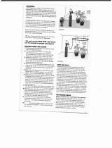
Installation
1. Fix the connection nut of the regulator on the thread of the CO
2
bottle (hand tight)
2. Adjust the pressure regulator ( fig2) and secure the connection nut with a spanner (size 23)
3. Connect the CO
2
- tube to the coresponding fitting(4). Remove the nut, and put it on the hose.
The hose is then fixed on the fitting with the nut.
1 working pressure gauge
2. storage pressure gauge
3. needle valve
4. CO
2
hose connection
5. securing nut
6. O-ring
7 .connector to bottle 0-ring

4
Adjustion
1. Open the needle valve (3) slightly
2. Open the valve at the CO
2
bottle (four full turns). The primary pressure gauge shows now 60 -
70 bars, the working pressure gauge 1.5 bar ( 1-2 bar).
3. Open the needle valve, until the desired number of bubbles is reached.
Bubble counter: The exact control of the flow rate is checked with the bubble counter.
Safety tips
- Never separate a stationary pressure regulator form a CO
2
bottle, if it is under pressure. Close
the bottle valve, and open the needle valve to release the gas befor you separate both units.
Keep all CO
2
pressure bottles away from heat.
3. CO
2
reactor 500
Use this reactor to replace CO
2
loss in freshwater or saltwater. This reactor has been designed for
underwater operation only. Read and follow all instructions in this leaflet carefully for best results.
fig 2: reactor
1. CO
2
- reactor
2. flow adjustion valve
3. rubber sucker
4. lid with inner pipe
5. bottom lid
6. spiral tube
7. closing cap
8. water connection
9. CO
2
connection
10. spare port
11. adjudtion valve
technical characteristics
unit CO
2
art no: 71111
CO
2
- connection port: 9 mm
CO
2
input tube connection 6 /4 mm, (1/4“)
water flow min 500l/h ( 125 gph),
max 1000 l/h (250 gph)
holding system rubber sucker
The unit is designed for aquariums up to 500 l ( 120 gal) and
10°KH (4 mmol alcalinity). It can be increased with up to 4
enlargements. Each enlagrement will increase the capacity for
300 l (80 gal).

5
Reactor tube assembly:
1. Attach both suction cups (3)
2. slide output adapter onto water output connection
Hint: The adapter can also be attached to the water output connection with a piece of hose to
lower the position of th unit in the aquarium.
3. Attach filter or circulating pump outlet with a piece of hose to the output adapter
tube. Minimum output for the circulation device through the output adapter is 100 l/h.
4. Attach the black CO
2
tube to the CO
2
connection.
5. Remove the cap (7)
6. Place reactor tube assembly into position
7. Hint: Allow the Reactor tube assembly to completely submerge and fill with water before
pressing the suction cups into position on the aquarium glass.
8. Turn on the circulation pump/filter unit. Warning: close the CO
2
hose to prevent water leakage.
fig 3: reactor fig 4: reactor mounting.
12. connection hose 13. minimum water level
Before using the reactor, the rest of the CO
2
system has to be assembled: The pressure regulator
regular has to be mounted on the pressure bottle station. As soon as the regulator and the
reactor have been mounted, the reactor can be adjusted:

6
CO
2
reactor adjustment:
1. Turn on the circulation pump to start the water flow.
2. Open the valve of the CO
2
pressure bottle
3. The working pressure gauge of the regular is set to 1.5 bar ( +/-
.5 bar)
4. open slowly the needle valve of the regular.
5. Check the flow of the CO
2
bubbles on the bubblöe counter. The
initial flow should be approx 15 bubbles/minute.
6. The CO
2
will flow into the reactor and dissolved in the water flow.
7. Determine the CO
2
content in the water using a pH controller or a
pH test. Take an initial pH reading before starting the reactor. Raise
the bubble count per minute daily until a reading of 7.0 – 7.4 ( for
freshwater aquaria) is reached. It may take some days, until the
proper CO
2
level is reached and maintained.
Check the pH value regually and adjust the CO
2
bubble count as
required.
The CO
2
gas in the pressure bottle is 99.8% pure carbon dioxide. The
remaining 0.02% are nitrogen, oxygen and other insoluble gases. These
impurities are collected in the CO
2
reactor and can decrease ist
efficiency. An air hole allows these gases to escape automatically, when
they reach a preset concentration. Because of this safety exhaust, the
reactor will work continously without interuption.
raising the carbonate hardness (alcalinity)
Aquarium water, freshwater or saltwater should have a minimum
carbonate hardness of 4 – 6 °KH (1.5 – 2 mmol/l). Below this limit, the
pH of the water cannot be stabilised. Biological processes produce
permanetly organic acids, that reduce the carbonate hardness. Filtration
with peat or the use of other acids ( Phosphoric acid or hydrochloric
acid). If peat products are used for filtration, the carbonate hardness of
the water should be checked weekly. If the KH drops below 4° in
freshwater or 6 ° in saltwater, it should be raised. We recommend the
buffer tablets AB Aqua Medic aqua+ KH.
Maintenance
Keep CO
2
reactor always clean. For cleaning, it can be completely
dissassemblied.
1. dismantle the reactor
2. Separate the reactor cover (4) from the reactor by twisting the
bayonet joint to the left.
Pull out the spiral tube insert (6)
3. Clean all parts under running water with the brush provided with the
kit.
4. reassemble the parts and install into the aquarium.
Enhancing the performance
The maximum capacity of the reactor is reached, when the inner tube
is completely filled with CO
2
- gas and a pH of 7.0 – 7.4 cannot be
reached. In this case, the capacity of the reactor can be increased
using an additional extension set. With this extension, it is possible to
dissolve more CO
2
.
Up to 4 extension sets can be connected to the reactor. If extension
sets are used, the pump capacity has to be increased.
The optimum CO
2
quantity
The amount of CO
2
, that can be dissolved in water depends mainly on
the carbonate hardness (alcalinity) of the water. The higher the
carbonate hardness, the higher is the CO
2
concentration – at the same
pH value. The
toxic level of the CO
2
-concentration is also depending on

7
the pH value. At pH 7.1 – 7.4 for freshwater and 8.1 – 8.4 for seawater the balance between free
CO
2
and carbonate hardness is reached. In this range, the CO
2
quantity is not dangerous for fish,
independent of the carbonate hardness.
4. bubble counter
Bubble counter with integrated non return valve and a strong mounting plate. The bubble counter
has to be mounted in a way, that he is always without pressure. The needle valve has to be
mounted between the CO
2
bottle and the bubble counter.
Content
1. CO
2
inlet, from the CO
2
pressure bottle
2. CO
2
exit port to the aquarium/CO
2
reactor
3. transparent counter tube
4. plug with connections
5. non return valve, with silicon“umbrella“
6. connection fitting, 1/6“
7. bubble inlet tube
8. holding clamp
9. holding plate
10 . rubber succer
Connections:
- inlet: flexible tube, 6/4 mm diameter. It is
connected to the fitting with the tranparent acrylic
pipe , going to the bottom of the counter and the non return valve
- outlet: flexible tube, 6/4 mm diameter.
Installation:
The mounting plate of the counter is fixed to the wall or the aquarium stand, near the CO
2
bottle.
It can either be mounted with the rubber succers on a glass plate (aquarium) or directly with
screws on the wall. The bubble counter is then opened carefully, filled for 1/3 with water, closed
again and carefully pressed into the holder. Take care to keep the O ring of the plug and the top
part of the transparent counter tube dry. If these parts are wet, the counter will not be CO
2
tight.
If both tubes are connected to the CO
2
reactor (or the filter) and the pressure, the needle valve of
the reactor can be opened. Now bubbles can be seen and counted at the bottom of the thin acrylic
tube. The quantity of the bubbles can be adjusted at the needle valve.
Maintenance
If the water in the bubble counter is evapüorated, it has to be renewed.
5. Assessories
As an assessory, to automise the CO
2
supply , the Aqua Medic solenoid valve can be connected
between pressure regulator ( regular) and bubble counter, as a night shut off. The CO
2
supply is
then only switched on during daytime (together with the light), when the plants use CO
2
. The
optimum method is, to control the solenoid valve by an pH computer. The CO
2
-supply is then
atomatically balanced with the needs, the pH value is kept constant.
6. Warranty
Should any defect in material or workmanship be found within 12 months of the date of purchase
AB Aqua Medic GmbH undertakes to repair or, at our option, replace the defective part free of
charge – always provided the product has been installed correctly, is used for the purpose that was
intended by us, is used in accordance with the operating instructions and is returned to us carriage
paid. The warranty term is not applicable on the all consumable products.

8
Proof of Purchase is required by presentation of an original invoice or receipt indicating the dealer’s
name, the model number and date of purchase, or a Guarantee Card if appropriate. This warranty
may not apply if any model or production number has been altered, deleted or removed,
unauthorised persons or organisations have executed repairs, modifications or alterations, or
damage is caused by accident, misuse or neglect.
We regret we are unable to accept any liability for any consequential loss.
Please note that the product is not defective under the terms of this warranty where the product,
or any of its component parts, was not originally designed and / or manufactured for the market in
which it is used.
These statements do not affect your statutory rights as a customer.
If your AB Aqua Medic GmbH product does not appear to be working correctly or appears to be
defective please contact your dealer in the first instance.
Before calling your dealer please ensure you have read and understood the operating instructions.
If you have any questions your dealer cannot answer please contact us.
Our policy is one of continual technical improvement and we reserve the right to modify and adjust
the specification of our products without prior notification.
AB AQUA MEDIC GmbH - Gewerbepark 24 - 49143 Bissendorf/Germany
- Technical changes reserved -
/