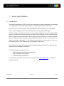
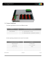
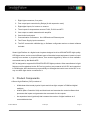
Natuled NAT_SLP004N is a Smart Light Platform that offers a wide range of features and possible use cases. With 4 light channels and 8 relay output ports, it allows you to control different types of electrical output equipment, including lights, motors, and sensors. The SLP is also equipped with 8 digital inputs, 3 temperature sensor inputs, and 4 USB ports, giving you the flexibility to connect a variety of devices. Whether you're looking to create a custom lighting system, automate your home, or control industrial equipment, the Natuled NAT_SLP004N is a versatile and powerful solution. Here are some specific examples of how you can use the SLP:
Natuled NAT_SLP004N is a Smart Light Platform that offers a wide range of features and possible use cases. With 4 light channels and 8 relay output ports, it allows you to control different types of electrical output equipment, including lights, motors, and sensors. The SLP is also equipped with 8 digital inputs, 3 temperature sensor inputs, and 4 USB ports, giving you the flexibility to connect a variety of devices. Whether you're looking to create a custom lighting system, automate your home, or control industrial equipment, the Natuled NAT_SLP004N is a versatile and powerful solution. Here are some specific examples of how you can use the SLP:


-
 1
1
-
 2
2
-
 3
3
-
 4
4
-
 5
5
-
 6
6
-
 7
7
-
 8
8
-
 9
9
-
 10
10
-
 11
11
-
 12
12
-
 13
13
-
 14
14
-
 15
15
-
 16
16
-
 17
17
-
 18
18
-
 19
19
-
 20
20
-
 21
21
-
 22
22
-
 23
23


Natuled NAT_SLP004N is a Smart Light Platform that offers a wide range of features and possible use cases. With 4 light channels and 8 relay output ports, it allows you to control different types of electrical output equipment, including lights, motors, and sensors. The SLP is also equipped with 8 digital inputs, 3 temperature sensor inputs, and 4 USB ports, giving you the flexibility to connect a variety of devices. Whether you're looking to create a custom lighting system, automate your home, or control industrial equipment, the Natuled NAT_SLP004N is a versatile and powerful solution. Here are some specific examples of how you can use the SLP:
Ask a question and I''ll find the answer in the document
Finding information in a document is now easier with AI
Other documents
-
LumiSource Indoor Furnishings User manual
-
 DROK 12v to 5v Buck Converter, LM2596 Adjustable DC Voltage Regulator 4-40V 24V Step-down to 1.23-37V 12V Volt Reducer Board 3A Power Supply Transformer Module User manual
-
Artsound ART24 Datasheet
-
Fibaro RGB Module Datasheet
-
Sanela SLP 32RZ Mounting instructions
-
Sanyo HT-F450AU User manual
-
-
Sunricher SR-WF1029-TY-RGBW User manual
-
Gossen MetraWatt METRAHIT 16I Product information
-
