Cherokee TS-300 User manual
- Category
- Power adapters & inverters
- Type
- User manual
This manual is also suitable for

Titanium
SST
Super
Surge Technology
Model:
TS-300
300
Watt
DC
to
AC
Power Inverter
User’s
Manual
CherokeeTH
Power
Inverters
A Division
of
Wireless
Marketing
Company
1212
Remington
Rd.
Schaurnburg,
IL
USA
60173

HOW
TO
USE
YOUR
Titanium
SST
Model:
TS-300
300
Watt
DC
to
AC
Power
Inverter
Introduction
3
How Your
Power InverterWorks
4
Safety
Information
5
Features
6
Installation
S
Operation
12
Applications
and
Limitations
13
Batteries
and
Alternators
14
About Power
and
Appliances
15
Low
Battery Alarm
15
Do’s
and Dcn’ts
1.6
Troubleshooting
17
Glossary
19
Specifications 20
Warranty
21
If
You
Need
Service
23
2

Introduction
CONGRATULATIONS..
You
have
just
purchased
one
of
the
world’s
foremost
DC to
AC
Power
Inverters,
the
Cherokee”’
Titanium
Super
Surge
Technology
(SST~
Model:
TS-300. This
technological
wonder
combines
superior product quality
with
innovative
circuitry and
advanced
design
that
make
it
tl~
premier power
inverter available
today.
SST greatly enhances
the
higher
starting
current
applications
where
the
power
inverter
can
be
used.
To
maximize
the
life
amd
use
of your
inverter,
proper installation is
critical.
Make
sure
that
whoever
does
the
installation
reads
the
entire
manual
before
starting
the
installation.
Pay
special
attenhion
to
CAUTION
and
WARNING
statements:
CAUTION
statements
help
avoid
situations
that
could result in
damage
to
ihe
power ~nverteror connected equipment.
WARNING
statements
alert
you
to avoid
conditions
that
can cause injury
or
loss
of life.
PLEASEREAD
THE
MANUAL
COMPLETELY
BEFORE
USING THE
POWER INVERTER.
3

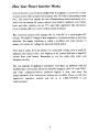
How
Your
Power
Inverter
Works
A
Rower
Inverter is
an
electronic product
that
is
designed to convert
the
12
volts
of direct current
(DC)
usually from a battery into
120
volts
of
alternafing
current
(AC).
This
conversion
enables
the
use
of
household products
and
power
tools
away
from
the normal
AC
power
sources
(wall
outlets).
Suddenly
cans,
inicks,
boats
and
other
vehicles
can
use
TX’s
and
other
aprliances
like
microwave
ovens.
Lighting
and
tools
can
be
used
in
remote
locations,
The
conversion
process
first
changes
the
12
volts
DC
to
a
much
higher
DC
voltage.
The
high
DC
voltage is then outputted in
a
forward
and
then
in
a
reverse
direction.
The
output
wavefoim
is
called
a
inod~f,ed
sine
wave
because
it
m.mic~
the
normal
AC
voltage
but
does
not
exactly
match.
Since
power
comes
from
the
product
of
current
and
voltage,
even
a
small AC
appliance
that
requires
only
a
few
amperes of AC
current
will
draw
a
large
DC
current
from your
battery.
Remember In
use
the
cables
that come
with
the
power
inverten
The
vast
majority
of
appliances
and
power
tools
have
no
problems with
the
modified
sine
wave
current.
However,
some
DC
chargers,
a
few
TV’s
and
VCR’s.
and some
compressoFdriven
products
require
a
purr
sine
wave
for
proper
operation.
Sine
wave
power inverters are
available.
Please consult your
appliances
operation
manual
and
call
us
at
I-800-’59-0~59
if
you
need
assktance.
4

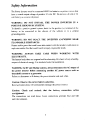
Safety
Information
The Power Inverter must
be
connected
ONLY
to batteries or power sources
bat
have a
normal
output
voltage
of
positive
12
volts
DC.
Do
not
use
a
6-volt or
24
you
battery
as
a
source
of
power.
WARNING:
DO
NOT
INSTALL
THE
POWER
INVERTER
IN
A
POSITIVE
GROUND
DC
SYSTEM.
To
identify
a
positive
gro~ind
system.
Look
for the
positive
(-.-)
terminal
of
the
battery
to be
connected
to the
chassis
of the
vehicle
or to
a
central
grounding
point.
WARNING: DO NOT
PLACE
THE
INVERTER
ANYWHERE
NEAR
FLAMMABLE
SUBSTANCES.
Fumes
and/o,-
gases
that
could
~me
into
contact
with
the
inverter
could
cause
an
explosion
and/or
fire
that
could
result
in
injury or
possible
death.
WARNING:
ALWAYS
TAKE CARE
WHEN
WORKING
WITH
ELECTRICITY.
The human
body
does
not
respond
~vell
to
electricity.
It is
best
to
keep
a
healthy
respect
of
electrical energy.
Use
insulated
tools
for installation.
WARNING:
In RV and
Marine
systems,
always
disconnect
the
AC
output
of
the
power
inverter
before
connecting
another AC
power
source such
as
household
current
or
a
generator.
Failure
to
disconnect
will
destroy
the
power
inverter
and
start
a
fire.
Caution:
Observe
the
correct
battery
polarities.
Reversed
connections
wil
I
permanently
damage
the
power
mater.
Caution:
Check
and
recheck
that
the
battery
connection
cables
are
tightened.
The
connections
can
work
loose.
Loose
connections
generate
beat and will
melt
the
tenninals.

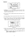
Features
(Front Panel)
A)
ON/OFF
Power switch:
This
switch
turns
the
output of
the
power
inverter
ON
or
OFF.
Note:
Even in OFF position the
power
inverter
draws a small
amount
of
current
from
the
battery.
B)
Power
Indicator:
When lit, indicates
that
the
inverter
has
been
timed
on,
and
is ready
for
use.
C)
Low
Battery
Indicator: When lit. indicates
that
the
battery voltage
is
too
low.
D)
Dual
ACOutlets:
Designed
to the NorthAmerican Standard,
they
provide
the
ability
to
connect
two
separate devices. Please nore
tat
the combined
required
wattage
must not exceed
the
capacity of
the
inverter.
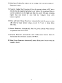
(Back
Panel)
E)
Battery Cable Connection
Posts(+
and
-):
Allows
for
the
connection of
the
cables from the power
inverter
to battery of the vehicle
that
is supplying
the
power
Caution:
Be
careful to
observe
the
correct polarities.
Red
is
for
positive
(4-). Black
is
for
negative
(-).
6

F)
High
SpeedCooling
Fan:
Allows
for
the
cooling ofthe
n~ernal
circuitry of
the
power
inverter.
G)
Cigarette Lighter Plug Connector: Allows the
inverter
to draw its DC power
directly from
the
cigaiette
light
plug
in
your
vehicle.
We
recommend
that you
use
this
connector
only
for
light
leads
that
draw
under
ISO
watts.
Anything
higher
than
that
should
he
used
with the
Alligator Clip”
cable
harness
supplied.
H) Over and Under
Voltage
Protection: Automatically shuls the power irverter
off
when the input
battery
voltage exceeds
14.7
volts
or drops
below
10.5
volts.
1)
Themial Protection: Automatically
shuts
the
power
inverter
when
internal
temperature
rises
above
I
50
0F.
.1)
Overload Protection: Automatically shuts
off
the power
inveder
when
the
load
exceeds
the
continuous
capacity:
300
Watts.
K)
Short
Circuit Protection: Automatically
shuts
off
the
power
invertc2r
when
the
output is shorted.
7

Installation
A)
Selecting
the
Battery
Power
Source:
The input power
source
you
are
conneding
to the
power
inverter
must have a
minimum
voltage
of
10.5
volts
to
a
maximum
of
14.5
volts DC. The power
source
most
likely
will
be
a combination a
vehicle’s
battery andalternator (when
tIle
vehicles
motor
is
running).
W4RNING~
DO
NO~
INSTALL THE
POWER
INVERTER IN
A
POSITIVE GROUND
DC
SYSTEM.
The 300
Watts
that
your power
nveaer
is capable of
supplying
requires
30
amperesof
inputcurrent.
This means
that
in order to
avoid
draining
the
battery,
the
alternator
must
be
able to provide
at
least
150
amps.
All
passenger
car
and
small
truck
alternators
are
this large.
Large
over-th&road
truck
alternators
are
200
amps
or
larger.
CAUTION:
The
power
inverter
must
he
connected
ONLY
to
bateries
or power
sources
thai
have
a
normal or
average
voltage
of
12
volts.
The power
iriverter
will
not
operate
from
a
6
volt or a
24
volt
power
source.
B)
Placement
of
the
Power
Inverter:
Placement of the
inverter
is
important
for
maximizing
the
usefulness
and
life of
the
power
inverter.
For the best results, the
inverter
should be placed
on
a
sturdy,
flat
surface.
Note:
The
power
inverter
can be mounted in any position:
vertical,
horizontal,
upright
or
inverted.
Consider
the
following
criteria
when
choosing
a
permanent
location:
1
Ventilation:
Make sure
there
is
at least
one
inch
of clearance around
the power
inverter
for
maximum
airflow.
This’
is
especiAlly
importa,it
when permanent mounting is being
considers.
Do not
place
objects
on
or over
the
power
inverter
during
use.
Air
must be able to
circulate.
The
built-in
cooling
fan
provides cooling,
but
must have
sufficient
open
space
to operate
properly,
In
the
event
that
internal

temperature exceeds
1504k
the
power
iawerter
will
automatically
shut
off.
2.
Dry:
Keep
Liquids,
water or any other type of wet substance
away
from
the
power
invert~.
When
choosing
a permanent
location,
stay
away from
spill
areas.
3.
Cool:
Best operating
emperaturc
range
is
between
45
and
85
0F Do
not place the power
inverter
in a
location
that could
be
affected
by
a
heating
duct or
any
other heat source
that
would
increase
the
normal
operating temperature of
the
power
inverter
-
4.
Safety:
Do
not
place
the
inverter
near flammable substances!!! Fumes
and
gases could
cause
and
explosion
or fire
that
would
result in
severe
damage
ard
possible
death.
C).
Cables
Connecting
the
Inverter
to
the
Battery:
Your
choice
of cable
is
the
single
most
important
factor
in
the
proper operation
of
the
power
irverter. It doesnot pay to purchase
low~cost
ineKpensive
cables
ai~d
expect
good
performance.
Your
power
invener
comes with
#10
AWG stranded copper wire with
good
quality insulation. The insulation of
the
wire from
the
negative terminal of
the
battery should
be
Hack
in
color
that
is
the
most
common
color
for
the negative
terminal
in vehicles. The insulation of
the
wire
from
the
positive
terminal of the
battery should
be
red or orange in
color.
Remember
to mount the power
inverter
as
close as possible to
the
battery to
give
best
performance.
9

B).
Grounding
the
Inverter:
WARNINGS:
DO
NOT
INSTALL
THE
POWER INVERTER
IN
A
POSITIVE
GROUND
DC
SYSTEM.
To
identify
a
positive
ground
system,
look
for
the
positive
(+)
terminal
of the battery connected to
the
chassis
of
the
vehicle
or
to
a
central
grounding
point.
E)
Fusing:
The cigarette
lighter
has
a
IS
Amp fuse.
The
larger
cables
have
a35
Amp
fuse.
Fuses can usually
be
pijrchased
at
auto
supply
stores.
F)
Connecting
to
the
Power
Source:
At full
power
of
300
watts,
the
power
inverter
will
be
drawing
28
amps fioni the
chosen
power
source.
The
usual
power
source
is
a battery (or
group
of
batteries)
which
is
recharged
by
an
alternator driven
by
an
engine.
Other
sourres
of recharging
such
as
wind or
solar
power
is
possible hut
requires
careful
design.
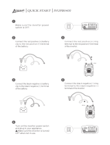
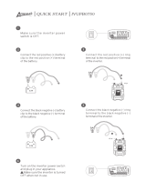
1.
Make
sure
the
power
switch
on
the
inverter
is
turned off and
no
liquids
are
near.
2.
You
will
need
to
determine which of
the
rower
cords is appropriate
for
the
application
you
are
trying to run. We
recommend
that
for
loads
up
to
150
Watts,
you
can
use the
cigarette
lighter
plug
that
is
connected
directly
to
the
inverter.
For
loads
between
150
Watts
and
300
Watts,
we
recommend
that
you
use
the direct
idring
harness
and
attach
it
to
The
terminal
connection
posts
on the
hack
of
the
inverter.
This
will
help
to insure sufficient and
consistent
power transfer to
the
attached
equipment.
3.
If
you use
the
cigarette
lighter
plug:
Simply
place
theplug
into
the
cigarette
lighter
of
your
vehicle.
4. If
you
use the
cable
harness
and
attaching it to
the
tentinal
posts
on
the
back of
the
inverta:
A)
Connect ends of the supplied cable, and
insert
them into their
respective terminals
on
the
back
of
the
inverter The black cable
goes
into the (4 negative
post.
then
the
red
cable
goes
into
the
(4-)
positive
post.
10

B)
Tighten
the
screws
sccurelv
to
hold
the
cables
in
place.
Make
suit
you
do
not
~.ver tighten to the point where
you
damage
the
wiring cable,
C)
Connect
the
cable
from
the
negative
(4
terminal of
the
inverter
to
the negative terminal of the
power
source. A
Rim.
secure
connection
here is very
important,
as
a
loosely tightened
connections
will
result
in
excessive
voltage
drop
and
may
cause
overheated
wires
and melted
insulation.
5. At
this
point,
make
sure
that you
have
properly connected the
negative terminal of
the
inverter
to the
negative
tcrniinal
of
the
power
Source.
WARNING:
REVERSING THE POLARITY
CONNECTIONS
WILL
CAUSE
PERMANENT
DAMAGE
TO
THE
POWER
INVERTER.
6.
Connect
the
cable from
the
posifive
terminal ol
Lhe
inverter
to
the
positive output terminal of
the
power
source.
It is
irnpwtant to
make
a
secure
connection.
WARNING:
You
may
observe
a
small
spark
when
you
make
this
connection
since
current
may
flow
from
the
power
source
and
charge
the
capacitors
in
the
inverter.
Make
sure
that
no
flammable
liquids,
or
fumes,
as an
explosion
may
result.
7.
Turn
the
POWER
switch
to
the
ON position.
The
POWER
li2ht
should come
on.
8.
Turn
the
POWER
switch
to OFF The
POWER light
will
go
off
and
an
internal
alarm
may sound.
The internal circuitry
is
resetting itself for
the
next
operation.
II

Operation
I)
Plug
the
AC,
power cord of the item to
be
powered
by
the
power
inverter
into one
of
the
AC
outlets.
Make sure the power of
the
connected
product
is
turned
OFF.
Important:
If
two
products
are
to
be
powered,
make
sure
that
the
total
wattage
does not
exceed
the
total
capacity
of
the
power
inverter.
2)
Turn
ON
the
power
invertet.
3)Now turn
on
your
connected
product.
If
you
have
two
products
connected, make
sure,
that
you turn
them
on
sepatately.
This
will insure
thai
the
power
inverter
does
not
have
to
deliver the “peak”
start-up
power
to
two
units
at
the
same
time.
12

Applications
and
Limitations
The
TS-300
will
operate
most
AC prodtict~
that
rail
within
its
power rating of
300
Wattsl
In the event
that
you
accidentally
overload
the
power
inverter,
it
will automatically
shut
down,
protected by the
built-in
overload
ctrcuitrv.
Once
the
overload
is
removed,
the
inverter
will
resume
normal
operation.
Most electronic
products
have
a
power consumption rating
label
that
rates
the
power needs
in
either
watts or
amps.
It
the
rating
is
given
in amps,
multiply
the
amps
rating
by
ICC
to
find
the
wattage.
If more
than
one product
is
to
be
powered,
add
the
~vattage
requirements
of both units.
The
lotal
muM
not
exceed
the
capacity of
the
power
inverter.
The
15-30(1
cannot operate
any
microwave
oven
or
motor-driven
equipment
since
these
appliances
draw
significantly
more
than
300
Watts.
Modified
Sine
Wave
The
AC
output
voltage
simulates
the AC
power
available
in
the
wall
outlets
of
your
home.
The
output
is
called
‘modified’
because it is
not
exactly
like
normal
AC
power.
While the
vast
majority of products
will
accept
this
type
of
power.
some
TVs.
small product
chargers,
computers,
etc.
require
true
Sine
Wave
power
Sine
Wave
power
inverters
are
available.
Please
call
us
at
1-800-259-0959
for
more
information.
13

About Batteries
and
Alternators
Batteries
that
are
installed in vehicles
store
energy developed
hy
a
running
engine
and
alternator
to
be
used
in
starting
the
vehicle.
The
batteiy
instantly
delivers
the
heavy
current
to
start
the
engine.
After
starting,
the
ukernator
recharges
the
bat
-
tery
for the
next
starting-cycle.
Normal barteries
are
not designed to provide smaller
cmrents
over long periods
of time This
is the reason
that
we
recommend
that
after
20
minutes of
operating
a
power
inverter, start
the
engine to
recharge
the
battery
and
keep
the
engine
and
alternator
running
to
power
the
power inverter.
The
power
inverter
can
be
used
either while the
engine
is
running
orturned
off
However,
the
power
inverter
may
not
operate
while
the
engine
is
starting,
since
the
battery
voltage
can
drop
substantially
during
start-up.
Deep
cycle
marine
and
RV
batteries
as
well
as
golf
cart
batteries
are
designed
specially
fo~
providing
power
over
longer
periods
of
time.
These
types
of
batteries
are
recommended
if
the
power
iriverter
is
to
be
used
for
long
periods
as
an alternative
to
regularAC
power.
Many
alternative
power systems use
solar
or
wind
generators
to
recharge
batteries
to
power
the
power
inverter.
Please
remember
that
these
sources of
power
as
usually
very
low
current.
It
could take days of charging for
only
short
periods
of
use.
14

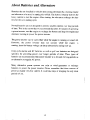
About
Power
and
Appliances
Electrical
power
is
measured in
watts.
One
theusand
watts
is
a
kiiowatt.
Power
is
the
product
(multiplication) of
the
voltage
(120
volts
AC)
and
the current
required
(amperes).
For
example
an
appliance
that
needs
ID
mps of current
is
asking
for
1200
watts
of
power
(10
times
120).
The
300-watt
power
inverter
is capable
of
providing
300
dividcd
by
120=
2.5
amperes of
current.
Therefore,
the
total
requirement
for appliances to be
powered
simultaneously is
300
watts
or
2.5
amperes.
Low
Battery
Alarm
Built into
the
power
invener
is
a.,
alarm
that
will sound when the
voltage
drops
to
10.5
volts.
Use of
the
power
inverter
should
stop,
as
the power
inverter
will
automatically shut down when
the
voltage
drops tc around
10
volts.
preventing
potential
damage
to
the
battery
and
allowing
enough
a,rrent
to
restart
the
engiuc.
IS

Do’s
and
Don’ts
Do’s
Do use
either
the
cables
that
came
with
the
power
inverter
or
alternative
thicker
diameter
cables.
Securely
mount
the
power
inverter
to a secure surface when permanently
mounting
the
power
inverter.
lake
care not to
damage
the
insulation of the cables.
Don’ts
Don’t
overload
the
inverter.
Don’t
use
6 or
24-Volt
batteries.
Don’t
use
small
diameter
cables.
Don’t
operate
near
fumes.
Don’t
drop
the
inverter.
Don’t
parallel
the
output
of
two
power
inverters.
Don’t
allow
the
power inverter
to
get
wet
Don’t
use
a
wet
power
inverter
or
wet
cables.
16

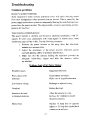
Troubleshooting
Common
problems
BUZZ
IN
AUDIO
SYSTEMS
Some
inexpensive
stereo systems
arid
boom
boxes
will
emit
a
tu~zing
sound
from
their
loudspeakers.when
operated from
an
inverter.
This is caused by
the
power
supply in
the
stereo system not adequately
filtering
the
modified
sine
wave
power
from
the
power
inverter.
The only
possible
soLution
is
purchasing
an
inex
-
pensive
AC
line
filter.
TELEVISION
INTERFERENCE
The
power
inverter
is
shielded
and
filtered
to
minimbe
interference
with
TV
signals.
In
some
cases, particularly with
weak
signals in remote
areas,
some
interference may
still
he
vi~ihlc. Try
the following measures:
I.
Position
the
power
inverter
as
far
away
from the television.
antenna
and
antenna
cable.
2.
Adjust
the
orientation of the
power
inverter.
television power
cord
and
antenna
cables
to
mimimize
interference.
3.
Make
sure
that
the
antenna
feeding the television provides
an
adequate
(snow-free) signal
and that the
antenna
cables
are
shielded.
Problem:
Lack
or
AC
Power
Output
Possible
Causes:
Suggested
Solutions:
Poor
contact
with Clean battery terminals
terminals Make sure of
a
good
connection
Low
battery
voltage
Recharge or replace
bAte?
Overload Reduce the
load
Inverter is hot
and
Allow
the
inverter
to
cool.
in
thermal shutdown
lncre.a~e
the
ventilation
around
the
power
inverter.
Blown
Fuse Replaee
15
Amp fuse in cigarette
lighter
or
35
Amp
fuse
inside black
connector
on
red
wire.
I?

Problem:
Low
Output
Voltage
Possible
Causes:
Using
average
reading
Voltmeter
Overheating
Low
Input
Voltage
Poor
battery
Suggested
Solutions:
Use
true
RMS
voltmeter
Reduce
load
Increase battery
size.
Check
cables and connections.
Problem:
Low
Battery
Alarm
Replace
bartery
Poor
connections
Check
cables and
connectors
NOTE:
To
accurately
measure
the
output
voltage,
you
must
use
a
True
RMS
Voltmeter.
A
normal
averaging
type
meter
will
read
a
lower
volt.g~
thai,
110-120
volts.
This
is
the
fault
of
the
meter
not
the
Power
Inverter.
Contact
us
with
any
questions
or
problems:
Cherokee
1” Customer Service
Phone:
1-800-250-0959
Fax:
1-847-839-0016
E-mail:
Web:
wwwwirrlessmarketing.com
18

Glossary:
AC
Alten,
am,
-
Amperes
Battery
Capacity
Current
DC
Modified Sine
Wave
Power
Power Converter
Power hwecter
Sine
Wave
Voltage
Volts
Watts
Alternating
Current. Normal
household power
Device
connected
to
the
engine usually
by
a
belt
that
recharges
the
battery
Unit
of measure
of
electrical current
(amps)
Chemical
Storage
device
to provide
starting
DC power
Amount
of
electricity
current
or
power
stored
in
a
battery
Flow
of
electrons measured
in
amperes
Direct
Current
power
stored in
a
battery
Shape
of
AC
power from Power Inverter
Electrical power measured
in
watts
Device
that converts
AC
to DC
Devices
which converts DC
to
AC
Shape
of
Normal
Household
AC
Force which pushes
electrons
out
of
a
Battery
through
a
wire
Unit of
jneasure
of
voltage
Unit of
measure
of power
19

Specifications
300 Watt Power Inverter
Maximum
Continuous
Output
Power
Surge
Capacity
(Peak
Poiver)
Optimum
Efficiency
Output
Waveform
DC Input
Voltage
Range
No
load
DC
Current
Draw
Low
Battery
Alarm
Low
Battery
Shutdown
Output
AC
Frequency
Output
AC
Voltage
Thermal
Protection Shutdown
AC
Receptacles
(North
American
Standard)
Warranty
Weight
Length
Width
Height
Country
of
Origin
300
Watts
800
watts
>90%
Modified
Sine
Wave
10-14
Volts
.2Amp
@10.5
Volts
@10.0
Volts
60Hz
110-115
Volts
ntis
>150
0F
Dual
3
years
3.0
lb
(1.36kg)
9.1”
(23m)
4.1”
(lOin)
2.3”
(.06m)
Taiwan
20
Page is loading ...
Page is loading ...
Page is loading ...
-
 1
1
-
 2
2
-
 3
3
-
 4
4
-
 5
5
-
 6
6
-
 7
7
-
 8
8
-
 9
9
-
 10
10
-
 11
11
-
 12
12
-
 13
13
-
 14
14
-
 15
15
-
 16
16
-
 17
17
-
 18
18
-
 19
19
-
 20
20
-
 21
21
-
 22
22
-
 23
23


Cherokee TS-300 User manual
- Category
- Power adapters & inverters
- Type
- User manual
- This manual is also suitable for
Ask a question and I''ll find the answer in the document
Finding information in a document is now easier with AI
Other documents
-
Radio Flyer 930Z User manual
-
 Ampeak 4332951763 User manual
-
 Ampeak 13 User manual
-
PEAK PKC0AW Owner's manual
-
 K KRIËGER KR1100 User guide
-
 PYLE Audio PLINV2 User manual
-
-
909 HT8750-AUOXY User manual
-
Samlexpower PST-30S-12E Owner's manual
-
Samlexpower PST-150S-12E Owner's manual


