
2016-01-29 X40223 rev. K
ATTENTION: Do not tamper with the unit or its controls. Call a qualified service technician.
INSTALLER / SERVICE TECHNICIAN: Use the information in this manual for the installation / servicing of the furnace and
keep the document near the unit for future reference.
These instructions must be read and understood completely before attempting installation.
HOMEOWNER: PLEASE Keep this manual nears the furnace for future reference.
Manufactured by:
Industries Dettson Inc.
Sherbrooke (Québec) Canada
www.dettson.com
c
us

2
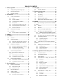
TABLE OF CONTENT
1- Safety regulation .............................................. 6
1.1- Safety labeling and warning signs ................ 6
1.2- Important information ................................... 6
1.3- Detection systems ........................................ 6
2- Introduction ....................................................... 8
2.1- Codes and standards ................................... 8
2.1.1- Safety ............................................................ 9
2.1.2- General installation ........................................ 9
2.1.3- Combustion and air ventilation....................... 9
2.1.4- Duct systems ................................................. 9
2.1.5- Acoustical lining and fibrous glass duct ......... 9
2.1.6- Gas piping and pipe pressure testing ............. 9
2.1.7- Electrical connections .................................... 9
2.2- Electrostatic discharge ................................. 9
2.3- Location ....................................................... 9
2.3.1- Location relative to cooling equipment ......... 10
3- venting ............................................................. 10
4- Installation ....................................................... 11
4.1- General ...................................................... 11
4.2- Upflow orientation ...................................... 11
4.2.1- Right side condensate drain connection ...... 12
4.2.2- Left side condensate drain connection ......... 12
4.3- Down flow orientation ................................. 12
4.3.1- Down flow condensate drain connection ...... 12
4.3.2- Downflow venting drainaged ........................ 13
4.3.3- Condensate box pressure switch ................. 13
4.4- Horizontal right orientation ......................... 13
4.4.1- Horizontal right condensate drain
connection ................................................................. 13
4.4.2- Horizontal right vent drainage ...................... 14
4.4.3- Condensate box pressure switch ................. 14
4.5- Horizontal left orientation ........................... 14
4.5.1- Horizontal left condensate drain connection 14
4.5.2- Condensate box pressure switch ................. 15
5- Duct installation .............................................. 15
5.1- Return air connections ............................... 15
5.1.1- Bottom return air inlet .................................. 15
5.1.2- Side return air inlet ...................................... 15
5.2- Filter arrangement ...................................... 15
5.3- Supply air ducts ......................................... 15
5.4- General requirements ................................ 15
5.4.1- Duct work acoustical treatment .................... 16
6- Gas piping ....................................................... 17
6.1- Gas pipe grommet ..................................... 18
7- Electrical connections .................................... 18
7.1- 120 V wiring ............................................... 18
7.2- 24 V wiring ................................................. 19
7.3- Thermostats ............................................... 19
7.4- Alternate power supply............................... 19
7.5- blower speeds (4 speed PSC motor) ......... 19
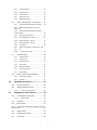
8- Venting ............................................................. 23
8.1- Special venting requirements for installations
in canada ................................................................. 23
8.2- General ...................................................... 23
8.3- Materials .................................................... 24
8.4- Direct vent (2 pipes applications) ............... 24
8.5- Non direct vent (1 pipe) applications .......... 24
8.5.1- TERMINATION REQUIREMENTS FOR THE
PROVINCE OF ALBERTA AND SASKATCHEWAN .. 24
8.6- Size of the vent and combustion air pipes.. 24
8.7- Connecting to furnace ................................ 25
8.7.1- Combustion air piping .................................. 25
8.7.2- Exhaust vent piping ..................................... 25
8.8- Combustion air and vent piping insulation
guidelines ................................................................ 28
8.9- Installing the vent termination .................... 28
8.9.1- Concentric vent ........................................... 28
8.9.2- Two pipes termination ................................. 28
8.9.3- Sidewall termination .................................... 29
9- Start up, adjustment and safety check ......... 29
9.1- To start the furnace .................................... 29
9.2- Unit operation hazard ................................. 29
9.3- Setup switches ........................................... 29
9.4- Option switches – 1 stage, PSC and x13 ... 29
9.4.1- Heat mode .................................................. 30
9.4.2- Cool mode ................................................... 30
9.4.3- Manual fan on mode .................................... 30
9.4.4- Twinning interface ....................................... 30
9.4.5- System lockout and diagnostic features ....... 30
9.4.6- System lockout features .............................. 30
9.4.7- Diagnostic features ...................................... 30
9.5- Option switches – 2 stage, PSC ................. 30
9.5.1- Heat mode .................................................. 31
9.5.2- Cool mode ................................................... 31
9.5.3- Manual fan on mode .................................... 31

3
9.5.4- Twinning interface ....................................... 31
9.5.5- System lockout ............................................ 31
9.5.6- Last fault mode ............................................ 31
9.5.7- Fault code reset ........................................... 32
9.5.8- Diagnostic features ...................................... 32
9.6- Option switch settings – 2 stage ECM ....... 32
9.6.1- Thermostat type and heat-fan-off delay ....... 32
9.6.2- Multi-stage thermostat set-up, factory
default 32
9.6.3- Single stage thermostat set-up, module
controls staging ......................................................... 32
9.6.4- Heat fan off delay timing .............................. 32
9.6.5- De-humidification connection ....................... 32
9.6.6- Normal operation – heat on ......................... 32
9.6.7- Normal operation – heat off ......................... 32
9.6.8- Cool mode ................................................... 33
9.6.9- Adjust cooling airflow – dipswitch S3-1 and
S3-2 33
9.6.10- Manual fan on mode ............................... 33
9.7- Troubleshooting ......................................... 33
9.7.1- System lockout ............................................ 33
9.7.2- System reset ............................................... 33
9.7.3- Thermostat reset ......................................... 33
9.7.4- Auto restart .................................................. 33
9.7.5- Diagnostic features ...................................... 33
9.7.6- Fault code retrieval ...................................... 33
9.7.7- CFM indicator .............................................. 33
9.8- Prime condensate trap with water .............. 34
9.8.1- Check safety controls .................................. 35
9.8.2- Checklist...................................................... 35
10- Operating your furnace ........................... 35
10.1- Start up instructions ................................... 35
10.2- Shutting down the furnace ......................... 35
10.2.1- To turn off gas to furnace ........................ 35
11- Maintenance of your furnace ................. 35
11.1- Cleaning/replacing the filter........................ 36
11.1.1- Filter location .......................................... 36
11.2- Lubrication ................................................. 36
11.3- Burner flame .............................................. 36
11.4- Condensate collection and disposal system
(if applicable) ........................................................... 36
11.5- Rollout switch ............................................. 36
11.6- Safety interlock switch ............................... 36
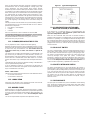
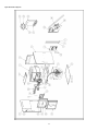
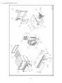
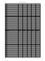
11.7- repair parts ................................................. 36

4
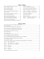
INDEX OF FIGURES
Figure 1 Freeze protection and return air temp. ............... 8
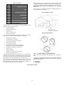
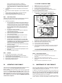
Figure 2 Installation in a garage ..................................... 10
Figure 3 Prohibited installation ....................................... 10
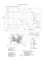
Figure 4 Dimensional drawing ........................................ 10
Figure 5 Vent coupling and adapter with gaskets ........... 25
Figure 6 Drain trap ......................................................... 11
Figure 7 Left side condensate drain connection ............. 12
Figure 8 : Down flow orientation ..................................... 13
Figure 9 Condensate pressure switch ............................ 13
Figure 10 Horizontal right drain trap position .................. 14
Figure 11 Horizontal right condensate tubing ................. 14
Figure 12 Pressure switch assembly .............................. 14
Figure 13 Horizontal left condensate drain connection .. 15
Figure 14 Return air base ............................................... 15
Figure 15 Typical gas pipe arrangement ........................ 17
Figure 16 Power cord installation in the furnace ............ 19
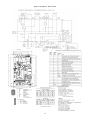
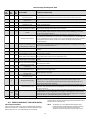
Figure 17 Wiring diagram – One stage PSC .................. 20
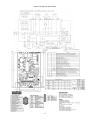
Figure 18 : Two Stage PSC - Furnace Control ............... 21
Figure 19 : Two Stage ECM - Furnace Control .............. 22
Figure 20 Electric diagram X13 ...................................... 23
Figure 21 Direct venting ................................................. 26
Figure 22 Multi venting ................................................... 26
Figure 23 Control Switch – Modulating Valve ............ 35
Figure 24 Typical Flame Appearance ........................ 36
INDEX OF TABLES
Table 1 Minimum clearance to combustible material for all units ............................................................................................... 9
Table 2 Loose parts list ............................................................................................................................................................ 10
Table 3 Air flow capacity and blower data 2 stage variable ...................................................................................................... 16
Table 4 : Air flow capacity and blower data 2 stage direct drive ............................................................................................... 16
Table 5 : Air flow capacity and blower date 1 stage direct drive ............................................................................................... 17
Table 6 Maximum capacity of pipe in Ft³ of gas/hr ................................................................................................................... 17
Table 7 Gas pressure ............................................................................................................................................................... 17
Table 8 Electrical data .............................................................................................................................................................. 18
Table 9 : Suggested fan speed on 1 stage furnace .................................................................................................................. 19
Table 10 : Suggested fan speed on 2 stage furnace ................................................................................................................ 19
Table 11 : Maximum equivalent straight vent length (two stage and modulating) .................................................................... 27
Table 12 Maximum equivalent straight vent length (single stage) ............................................................................................ 27
Table 13 Deduction for fitting ................................................................................................................................................... 27
Table 14 Approved combustion air and vent pipe, fitting and cement materials (U.S.A. Installation) ....................................... 27
Table 15: Option switches positions..................................................................................................................................... 29
Table 16: Option switches S1-3 & S1-4 positions ................................................................................................................ 31
Table 17: Option switches S1-1 & S1-2 positions ................................................................................................................ 31
Table 18: Duty cycles ........................................................................................................................................................... 31
Table 19: DIP Switches ........................................................................................................................................................ 32
Table 20: Duty cycle ............................................................................................................................................................ 32
Table 21: DIP Switches ........................................................................................................................................................ 32
Table 22 : Dipswitch setting for airflow selection ...................................................................................................................... 33

5
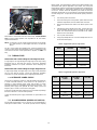
REQUIRED NOTICE FOR MASSACHUSETTS INSTALLATIONS
IMPORTANT
The Commonwealth of Massachusetts requires compliance with regulation 248 CMR as follows:
5.08: Modifications to NFPA-54, Chapter 10. Revise 10.8.3 by adding the following additional requirements:
For all side wall horizontally vented gas fuelled equipment installed in every dwelling, building or structure used in whole or in part for residential
purposes, including those owned or operated by the commonwealth and where the side wall exhaust vent termination is less than seven (7)
feet above finished grade in the area of the venting, including but not limited to decks and porches, the following requirements shall be satisfied:
Installation of Carbon Monoxide Detectors
At the time of installation of the side wall horizontal vented gas fuelled equipment, the installing plumber or gas fitter shall observe that a hard
wired carbon monoxide detector with an alarm and battery backup is installed on the floor level where the gas equipment is to be installed. In
addition, the installing plumber or gas fitter shall observe that a battery operated or hard wired carbon monoxide detector with an alarm is
installed on each additional level of the dwelling, building or structure served by the side wall horizontal vented gas fuelled equipment. It shall
be the responsibility of the property owner to secure the services of qualified license professionals for the installation of hard wired carbon
monoxide detectors.
In the event that the side wall horizontally vented gas fuelled equipment is installed in a crawl space or an attic, the hard wired carbon monoxide
detector with alarm and battery backup may be installed on the next adjacent floor level.
In the event that the requirements of this subdivision cannot be met at the time of completion of installation, the owner shall have a period of
thirty (30) days to comply with the above requirement; provided, however, that during said thirty (30) day period, a battery operated carbon
monoxide detector with an alarm shall be installed.
APPROVED CARBON MONOXIDE DETECTORS: Each carbon monoxide detector as required in accordance with the above provision shall
comply with NFPA 720 and be ANSI/UL 2034 listed and IAS certified.
SIGNAGE: A metal or plastic identification plate shall be permanently mounted to the exterior of the building at a minimum height of eight (8)
feet above grade directly in line with the exhaust vent terminal for the horizontally vented gas fuelled heating appliance or equipment. The sign
shall read, in print size no less than in-half (1/2) inch in size, “gas vent directly below. Keep clear of all obstruction”.
INSPECTION: the state of local gas inspector of the side wall horizontally vented gas fuelled equipment shall not approve the installation
unless, upon inspection, the inspector observes carbon monoxide detectors and signage installed in accordance with the provisions of 248
CMR 5.08 (2) (a) 1 through 4:
EXEMPTION: the following equipment is exempt from 248 CMR 5.08(2) (a) 1 through 4:
The equipment listed in Chapter 10 entitled “equipment not required to be vented “in the most current edition of NFPA 54 as adopted by the
board; and
Product approved side wall horizontally vented gas fuelled equipment installed in a room or structure separate from the dwelling, building or
structure in whole or in part for residential purposes.
MANUFACTURER REQUIREMENTS – GAS EQUIPMENT VENTING SYSTEM PROVIDED
When the manufacturer of product approved side wall horizontally vented gas equipment provides a venting system design or venting system
component with the equipment, the instructions provided by the manufacturer for installation of the equipment and the venting system shall
include:
Detailed instructions for the installation of the venting system design or the venting system components; and a complete parts list for the
venting system design or venting system.
MANUFACTURER REQUIREMENTS – GAS EQUIPMENT VENTING SYSTEM PROVIDED
When the manufacturer of product approved side wall horizontally vented gas fuelled equipment does not provide the parts or venting the flue
gases, but identifies “special venting system”, the following requirements shall be satisfied by the manufacturer:
The referenced “special venting system” shall be product approved by the board, and the instruction for that system shall include a parts list
and detailed installation instructions.
A copy of all installation instructions for all product, approved side wall horizontally vented gas fuelled equipment, all venting instructions, all
part s lists for venting instructions, and/or all venting design instructions shall remain with the appliance or equipment at the completion of the
installation.
For questions regarding these requirements, please contact the Commonwealth of Massachusetts board of State Examiners
of Plumbers and Gas Fitters, 239 Causeway Street, Boston, MA, 02114, tel.: 617 727-9952.

6
1- SAFETY REGULATION
1.1- SAFETY LABELING AND WARNING SIGNS
The words DANGER and WARNING are used to identify the levels of
seriousness of certain hazards. It is important that you understand their
meaning. You will notice these words in the manual as follows:
DANGER
Immediate hazards that WILL result in death, serious bodily injury
and/or property damage
WARNING
Hazards or unsafe practices that CAN result in death, bodily injury
and/or property damage.
NOTE: is used to highlight suggestions which will result in enhanced
installation, reliability or operation.
1.2- IMPORTANT INFORMATION
DANGER
Non-observance of the safety regulations outlined in this manual will
potentially lead to consequences resulting in death, serious bodily injury
and/or property damage.
It is the homeowner’s responsibility to engage a qualified technician for the
installation and subsequent servicing of this furnace;
Before calling for service, be sure to have the information page of your
manual close by in order to be able to provide the contractor with the
required information, such as the model and serial numbers of the furnace.
WARNING
Installations and repairs performed by unqualified persons can result in
hazards to them and to others. Installations must conform to local codes
or, in the absence of same, to codes of the country having jurisdiction.
The information contained in this manual is intended for use by a
qualified technician, familiar with safety procedures and who is
equipped with the proper tools and test instruments
1.3- DETECTION SYSTEMS
It is recommended that carbon monoxide detectors be installed wherever
oil or gas fired heaters are used. Carbon monoxide can cause bodily harm
or death. For this reason, agency approved carbon monoxide detectors
should be installed in your residence and properly maintained to warn of
dangerously high carbon monoxide levels.
There are several sources of possible smoke and flames in a residence.
Smoke and flames can cause bodily harm or death. For this reason, agency
approved smoke detectors should be installed in your residence and
properly maintained, to warn early on, of a potentially dangerous fire. Also,
the house should be equipped with approved and properly maintained fire
extinguishers.
Your unit is equipped with safety devices that can prevent it from
functioning when anomalies are detected such as a blocked venting
system.
WARNING
CARBON MONOXIDE POISONING/COMPONENT DAMAGE
HAZARD
Failure to follow this warning could result in personal injury or death and
unit component damage.
Corrosive or contaminated air may cause failure of parts containing flue
gas, which could leak into the living space. Air for combustion must not
be contaminated by halogen compounds, which include fluoride,
chloride, bromide, and iodide. These elements can corrode heat
exchangers and shorten furnace life. Air contaminants are found in
aerosol sprays, detergents, bleaches, cleaning solvents, salts, air
fresheners, and other household products. Do not install furnace in a
corrosive or contaminated atmosphere. Make sure all combustion and
circulating air requirements are met, in addition to all local codes and
ordinances.
WARNING
FIRE, EXPLOSION, ELECTRICAL SHOCK, AND CARBON
MONOXIDE POISONING HAZARD
Failure to follow this warning could result in dangerous operation,
personal injury, death, or property damage. Improper installation,
adjustment, alteration, service, maintenance, or use can cause carbon
monoxide poisoning, explosion, fire, electrical shock, or other conditions
which may cause personal injury or property damage. Consult a
qualified service agency, local gas supplier, or your distributor or branch
for information or assistance. The qualified service agency must use
only factory authorized and listed kits or accessories when modifying
this product.
WARNING
FIRE, EXPLOSION, AND CARBON MONOXIDE POISONING
HAZARD
Failure to follow this warning could result in personal injury, death, or
property damage.
Never operate a furnace without a filter or filtration device installed.
Never operate a furnace with filter or filtration device access doors
removed.
Untrained personnel can perform basic maintenance functions such as
cleaning and replacing air filters. All other operations must be performed
by trained service personnel. When working on heating equipment,
observe precautions in literature, on tags, and on labels attached to or
shipped with furnace and other safety precautions that may apply.
These instructions cover minimum requirements and conform to existing
national standards and safety codes. In some instances, these instructions
exceed certain local codes and ordinances, especially those that may not
have kept up with changing residential construction practices. We require
these instructions as a minimum for a safe installation.
Follow all safety codes. Wear safety glasses, protective clothing, and work
gloves. Have a fire extinguisher available. Read these instructions
thoroughly and follow all warnings or cautions included in literature and
attached to the unit.

7
WARNING
Sheet metal parts may have sharp edges or burrs. Use care and wear
appropriate protective clothing, safety glasses and gloves when
handling parts, and servicing furnaces
1. Use only with type of gas approved for this furnace. Refer to
the furnace rating plate.
2. Install this furnace only in a location and position as specified
in section 2.3- Location.
3. Provide adequate combustion and ventilation air to the
furnace space as specified in section 8-Venting.
4. Combustion products must be discharged outdoors. Connect
this furnace to an approved vent system only, as specified in in
section 8-Venting of these instructions.
5. Never test for gas leaks with an open flame. Use a
commercially available soap solution made specifically for the
detection of leaks to check all connections, as specified in the
“Gas Piping” section.
6. Always install furnace to operate within the furnace’s
intended temperature rise range with a duct system which has an
external static pressure within the allowable range, as specified
in section 5-Duct installation. See furnace rating label.
7. When a furnace is installed so that supply ducts carry air
circulated by the furnace to areas outside the space containing
the furnace, the return air shall also be handled by duct(s) sealed
to the furnace casing and terminating outside the space
containing the furnace. See section 5-Duct installation.
8. A gas fired furnace for installation in a residential garage
must be installed as specified in section 2.3-Location.
9. The furnace may be used for construction heat provided that
the furnace installation and operation complies with section 2.3-
Location.
10. The furnace is factory shipped for use with natural gas. A
CSA (A.G.A. and C.G.A.) listed accessory gas conversion kit is
required to convert furnace for use with propane gas.
11. See Table 1 Minimum clearance to combustible material
for all units for required clearances to combustible construction.
12. Maintain a 1” (25 mm) clearance from combustible materials
to supply air ductwork for a distance of 36” (914 mm) horizontally
from the furnace. See NFPA 90B or local code for further
requirements.
13. These furnaces SHALL NOT be installed directly on
carpeting, tile, or any other combustible material other than wood
flooring.
14. This gas furnace may be used for heating buildings under
construction provided that it follows the instructions mentioned in
the Warning box below.
WARNING
PERSONAL INJURY AND/OR PROPERTY DAMAGE HAZARD
Improper use or installation of this furnace may result in premature
furnace component failure. This gas furnace may be used for heating
buildings under construction provided that:
The furnace is permanently installed with all electrical wiring, piping,
venting and ducting installed according to these installation instructions.
A return air duct is provided, sealed to the furnace casing, and
terminated outside the space containing the furnace. This prevents a
negative pressure condition as created by the circulating air blower,
causing a flame rollout and/or drawing combustion products into the
structure.
The furnace is controlled by a thermostat. It may not be “hot-wired” to
provide heat continuously to the structure without thermostatic control.
Clean outside air is provided for combustion. This is to minimize the
corrosive effects of adhesives, sealers and other construction materials.
It also prevents the entrainment of drywall dust into combustion air,
which can cause fouling and plugging of furnace components.
The temperature of the return air to the furnace is maintained between
60°F (16 °C) and 80°F (27 °C), with no evening setback or shutdown.
The air temperature rise is within the rated rise range on the furnace
rating plate, and the gas input rate has been set to the nameplate value.
The filters used to clean the circulating air during the construction
process must be either changed or thoroughly cleaned prior to
occupancy.
The furnace, ductwork and filters are cleaned as necessary to remove
drywall dust and construction debris from all HVAC system components
after construction is completed.
WARNING
Frozen and burst water pipe hazard
Failure to protect against the risk of freezing may result in property
damage. Special precautions MUST be made if installing furnace in an
area which may drop below freezing. This can cause improper operation
or damage to equipment. If furnace environment has the potential of
freezing, the drain trap and drain line must be protected
WARNING
FIRE, INJURY OR DEATH HAZARD
Failure to follow this warning could result in personal injury, death
and/or property damage.
When the furnace is installed in a residential garage, the burners and
ignitions sources must be located at leat 18” (457 mm) above the floor.
The furnace must be located or protected to avoid damage by vehicles.
When the furnace is installed in a public garage, airplane hangar, or
other building having a hazardous atmosphere, the furnace must be
installed in accordance with the NFPA 54/ANSI Z223.1-2009 or
CAN/CSA B149.2-2010 (Figure 2 Installation in a garage)
Do not install the furnace on its back or hang furnace with control
compartment facing downward. Safety control operation will be
adversely affected. Never connect return air duct to the back of the
furnace. (Figure 3 Prohibited installation)
CAUTION
Property damage hazard
Failure to follow this caution may result in burst water pipes and/or
property damage. If a condensate pump is installed, a plugged
condensate drain or a failed pump may cause the furnace to shut down.
Do not leave the home unattended during freezing weather without
turning off water supply and draining water pipes or otherwise
protecting against the risk of frozen pipes.
Ensure all condensate drain connections are secured and liquid tight.

8
CAUTION
FURNACE CORROSION HAZARD
Failure to follow this caution may result in furnace damage. Air for
combustion must not be contaminated by halogen compounds, which
include fluoride, chloride, bromide, and iodine. These elements can
corrode heat exchangers and shorten furnace life. Air contaminants are
found in aerosol spray, detergents, bleaches, cleaning solvents, salts,
air fresheners, and other household products.
WARNING
CARBON MONOXIDE POISONING HAZARD
Failure to follow this warning could result in personal injury or death.
The operation of exhaust fans, kitchen ventilation fans, clothes dryers,
attic exhaust fans or fireplaces could create a NEGATIVE PRESSURE
CONDITION at the furnace. Make-up air MUST be provided for the
ventilation devices, in addition to that required by the furnace.
WARNING
CARBON MONOXIDE POISONING HAZARD
Failure to follow the steps outlined below for each appliance connected
to the venting system being placed into operation could result in carbon
monoxide poisoning or death. The following steps shall be followed for
each appliance connected to the venting system being placed into
operation, while all other appliances connected to the venting system
are not in operation:
1. Seal any unused openings in venting system;
2. Inspect the venting system for proper size and horizontal
pitch, as required in the National Fuel Gas Code, NFPA
54/ANSI Z223.1-2009 and these instructions. In Canada, refer
to CAN/CSA-B149.1-2010. Determine that there is no
blockage or restriction, leakage, corrosion and other
deficiencies, which could cause an unsafe condition
3. As far as practical, close all building doors and windows and
all doors between the space in which the appliance(s)
connected to the venting system are located and other spaces
of the building.
4. Close fireplace dampers.
5. Turn on clothes dryers and any appliance not connected to
the venting system. Turn on any exhaust fans, such as range
hoods and bathroom exhausts, so they are operating at
maximum speed. Do not operate a summer exhaust fan.
6. Follow the lighting instructions. Place the appliance being
inspected into operation. Adjust the thermostat so appliance
is operating continuously.
7. Test for spillage from draft hood equipped appliances at the
draft hood relief opening after 5 minutes of main burner
operation. Use the flame of a match or candle.
8. If improper venting is observed during any of the above tests,
the venting system must be corrected in accordance with the
National Fuel Gas Code, NFPA 54/ANSI Z223.1-2009. In
Canada, refer to CAN/ CSA-B149.1-2010.
9. After it has been determined that each appliance connected
to the venting system properly vents when tested as outlined
above, return doors, windows, exhaust fans, fireplace
dampers and any other gas-fired burning appliance to their
previous conditions of use.
WARNING
CARBON MONOXIDE POISONING HAZARD
For all venting configurations for this appliance and other gas
appliances placed into operation for the structure, provisions for
adequate combustion air and ventilation must be provided in
accordance with:
U.S.A. Installations: Section 9.3 NFPA 54/ANSI Z223.1 1−2009, Air for
Combustion and Ventilation and applicable provisions of the local
building codes.
Canadian Installations: Part 8 of CAN/CSA−B149.1−10. Venting
Systems and Air Supply for Appliances and all authorities having
jurisdiction.
2- INTRODUCTION
This 4-way multi-positioning Category IV condensing furnace is CSA
design certified as a direct vent (2 pipes) or non-direct vent (1 pipe). The
furnace is factory shipped for use with natural gas. The furnace can be
converted in the field for use with propane gas when a factory supplied
conversion kit is used. Refer to the furnace rating plate for conversion kit
information or to the appropriate part list at the end of this manual.
This Category IV furnace is approved for installation in
Manufactured/Mobile housing. The furnace must be installed in accordance
with the instruction provided in this manual. Follow all national and local
codes and standards in addition to these instructions. The installation
must comply with regulations of the serving gas supplier, local building,
heating, plumbing, and other codes.
This furnace is designed for minimum continuous return air temperature of
60 °F (16 °C) or intermittent operation down to 55 °F (13 °C) such as when
used with a night setback thermostat. Return air temperature must not
exceed 80 °F (27 °C). Failure to follow these return air temperature limits
may affect reliability of heat exchangers, motors, and controls (Figure 1
Freeze protection and return air temp.).
The furnace should be sized to provide 100 % of the design heating load
requirement plus any margin that occurs because of furnace model size
capacity increments. Heating load estimates can be made using approved
methods available from Air Conditioning Contractors of America (Manual
J); American Society of Heating, Refrigerating, and Air Conditioning
Engineers; or other approved engineering methods. Excessive over sizing
of the furnace could cause the furnace and/or vent to fail prematurely.
2.1- CODES AND STANDARDS
Figure 1 Freeze protection and return air temp.
Follow all national and local codes and standards in addition to these
instructions. The installation must comply with regulations of the serving
gas supplier, local building, heating, plumbing, and other codes. In absence
of local codes, the installation must comply with the national codes listed
below and all authorities having jurisdiction. In the United States and
Canada, follow all codes and standards for the following:

9
2.1.1- Safety
USA: National Fuel Gas Code (NFGC) NFPA 54-2009/ANSI Z223.1-
2009 and the Installation Standards, Warm Air Heating and Air
Conditioning Systems ANSI/NFPA 90B
CANADA: National Standard of Canada, Natural Gas and Propane
Installation Code (NSCNGPIC) CAN/CSA B149.1-2010
2.1.2- General installation
USA: NFGC and the NFPA 90B. For copies, contact the National Fire
Protection Association Inc., Battery march Park, Quincy, MA
02269; or for only the NFGC contact the American Gas
Association, 400 N. Capitol, N.W.,Washington DC 20001
CANADA: NSCNGPIC. For a copy, contact Standard Sales, CSA
International, 178 Rexdale Boulevard, Etobicoke (Toronto),
Ontario, M9W 1R3, Canada
2.1.3- Combustion and air ventilation
USA: Section 9.3 of the NFPA54/ANSI Z223.1-2009 Air for
Combustion and Ventilation
CANADA: Part 8 of the CAN/CSA B149.1-2010, Venting Systems and Air
Supply for Appliances
2.1.4- Duct systems
USA and CANADA: Air Conditioning Contractors Association
(ACCA) (Manual D), Sheet Metal and Air Conditioning
Contractors National Association (SMACNA), or American
Society of Heating, Refrigeration, and Air Conditioning
Engineers (ASHRAE).
2.1.5- Acoustical lining and fibrous glass duct
USA and CANADA: current edition of SMACNA, NFPA 90B as tested by
UL Standard 181 for Class I Rigid Air Ducts.
2.1.6- Gas piping and pipe pressure testing
USA: NFPA 54/ANSI Z223.1-2009 NFGC; Chapters 5, 6, 7, and 8
and national plumbing codes.
CANADA: CAN/CSA-B149.1-2010, Parts 4, 5, 6, and 9.
IN THE STATE OF MASSACHUSETTS:
This product must be installed by a licensed plumber or gas fitter.
When flexible connectors are used, the maximum length shall not
exceed 36”. (914 mm).
When lever type gas shutoffs are used they shall be "T" handle
type.
The use of copper tubing for gas piping is not approved by the state
of Massachusetts.
2.1.7- Electrical connections
USA: National Electrical Code (NEC) ANSI/NFPA 70-2011
CANADA: CAN/CSA-B149.1-2010, Parts 4, 5, 6, and 9.
2.2- ELECTROSTATIC DISCHARGE
CAUTION
FURNACE RELIABILITY HAZARD
Failure to follow this caution may result in unit component damage.
Electrostatic discharge can affect electronic components. Take
precautions during furnace installation and servicing to protect the
furnace electronic control. Precautions will prevent electrostatic
discharges from personnel and hand tools which are held during the
procedure. These precautions will help to avoid exposing the control to
electrostatic discharge by putting the furnace, the control, and the
person at the same electrostatic potential.
1) Disconnect all power to the furnace. Multiple disconnects may be
required. DO NOT TOUCH THE CONTROL OR ANY WIRE
CONNECTED TO THE CONTROL PRIOR TO DISCHARGING
YOUR BODY’S ELECTROSTATIC CHARGE TO GROUND.
2) Firmly touch the clean, unpainted, metal surface of the furnace
chassis which is close to the control. Tools held in a person’s
hand during grounding will be satisfactorily discharged.
3) After touching the chassis, you may proceed to service the
control or connecting wires as long as you do nothing to recharge
your body with static electricity (for example; DO NOT move or
shuffle your feet, do not touch ungrounded objects, etc.).
4) If you touch ungrounded objects (and recharge your body with
static electricity), firmly touch a clean, unpainted metal surface of
the furnace again before touching control or wires.
5) Use this procedure for installed and uninstalled (ungrounded)
furnaces.
6) Before removing a new control from its container, discharge your
body’s electrostatic charge to ground to protect the control from
damage. If the control is to be installed in a furnace, follow items
1 through 4 before bringing the control or yourself in contact with
the furnace. Put all used and new controls into containers before
touching ungrounded objects.
7) An ESD service kit (available from commercial sources) may
also be used to prevent ESD damage.
2.3- LOCATION
General
These furnaces are shipped with materials to assist in proper furnace
installation. These materials are shipped in the main blower compartment.
See Table 2 Loose parts list for loose parts bag contents. This furnace
must:
Be installed so the electrical components are protected from water;
Not be installed directly on any combustible material other than
wood flooring;
Be located close to the chimney or vent and attached to an air
distribution system. Refer to section 5 Ducts section;
Be provided ample space for servicing and cleaning. Always
comply with minimum fire protection clearances shown in Table 1
Minimum clearance to combustible material
for all units or on the furnace rating label.
Table 1 Minimum clearance to combustible material
for all units
Position
Clearance in (mm)
Rear
0
Front
0
Required for service (front)
*24'' (610)
All sides of supply plenum
*1''(25)
Sides
0
Vent
0
Top of furnace
1''
*See local buildings codes.

10
Table 2 Loose parts list
Quantity
Description
1
Plastic cap 5/8"
6
Plastic cap 1/2"
10
Screw TEKS HEX WSH #8-18 x ½
1
2" PVC pipe (Length = 1.5" OR 6.75")
1
Drain trap
1
Drain trap gasket
2
Gasket wall pipe flange
2
Wall pipe flange
1
Clear PVC tube 5/8" ID x 24"
1
Clear PVC tube 1/2" ID x 24"
1
Square PVC tube 3/16’’ ID x 8”
1
Brown wire (only used in Downflow and
horizontal configuration)
The following types of furnace installations may require OUTDOOR AIR for
combustion due to chemical exposures:
Commercial buildings
Buildings with indoor pools
Laundry rooms
Hobby or craft rooms, and
Chemical storage areas
If air is exposed to the following substances, it should not be used for
combustion air and outdoor air may be required for combustion:
Permanent wave solutions
Chlorinated waxes and cleaners
Chlorine based swimming pool chemicals
Water softening chemicals
De-icing salts or chemicals
Carbon tetrachloride Halogen type refrigerants
Cleaning solvents (such as perchloroethylene)
Printing inks, paint removers, varnishes, etc.
Hydrochloric acid
Cements and glues
Antistatic fabric softeners for clothes dryers
Masonry acid washing materials
All fuel burning equipment must be supplied with air for fuel combustion.
Sufficient air must be provided to avoid negative pressure in the equipment
room or space. A positive seal must be made between the furnace cabinet
and the return air duct to prevent pulling air from the burner area.
Place the unit so that proper venting can be achieved, with a minimum
number of elbows, in accord with the instructions in this manual. The
furnace should be located as close to the chimney (vertical venting) or to
the outside vent wall (horizontal venting) as possible.
When installing the furnace, provisions must be made to insure the supply
of adequate combustion and ventilation air in accordance with the air for
combustion and ventilation section of the National Fuel Gas Code, NFPA
5/ANSI Z223.1-2002, or latest edition, or applicable provisions of the local
building code.
If this furnace is to be installed in downflow or horizontal position, see
section 4-Installation of this manual.
Figure 2 Installation in a garage
Figure 3 Prohibited installation
2.3.1- Location relative to cooling equipment
The cooling coil can be installed in the supply air duct or in the return air
duct.
It is strongly recommended to locate the cooling coil at least 6” above heat
exchanger. This is to prevent any damage to the coil itself or unexpected
behavior of the condenser.
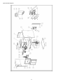
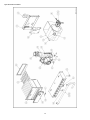
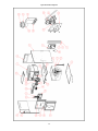
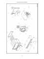
3- VENTING
Figure 4 Dimensional drawing

11
NOTE:
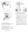
4- INSTALLATION
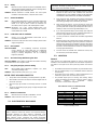
4.1- GENERAL
The furnace is factory built for upflow position. In this position, the drain
trap can be installed on right or left side depending on air return duct.
To ensure proper drainage of the condensate, tilt the furnace by
raising the back by 1’’.
When installing the furnace in other orientation than the upflow position,
simply configure the condensate tubing accordingly with the instructions
provided in this section of the manual.
Figure 5 Drain trap
4.2- UPFLOW ORIENTATION
In the Upflow orientation, the condensate trap can be to the right or to the
left of the furnace. The condensate drain must be routed from the trap
through the furnace casing. Remove the knock out parts of metal and

12
route the hoses to the drain trap. The condensate drain can be routed
through the left (Figure 6 Left side condensate drain connection or right (
Figure 6 Left side condensate drain connection
4.2.1- Right side condensate drain connection
1. Remove the oblong knock-out from the right side of the casing.
2. Place the drain trap gasket on drain trap, in a way that the holes
are aligned.
3. Install the drain trap on the right side, the three outlet stub of the
drain trap toward the interior of the furnace. The three outward
stubs ends are now inside the furnace.
4. Screw in place the drain trap with two head tapping screws on
the right side of the furnace.
5. Connect the outlet drain from the drain trap to an additional
condensate piping using a ½’’ tee for an adequate drainage of
the condensate. DO NOT vent using the remaining 3 outlet
stubs.
6. On the remaining 3 outlet stub, connect black vinyl cap (1x5/8’’
and 2x1/2”). Those cap are furnished in the loose part bag.
4.2.2- Left side condensate drain connection
1. Remove the oblong knock-out from the side of the casing.
2. Place the drain trap gasket on drain trap.
3. Install the drain trap on the side, the three outlet stubs of the drain
trap toward the interior of the furnace. The three outward stubs
are now inside the furnace.
4. Connect each of condensate tubes to a stubs. The condensate
hose from the condensate box is 5/8’’ and it must be connected
to the 5/8’’ stub of the drain trap. The condensate hoses from the
ID blower and the vent flange are ½” and are connected to the
½” stub of the drain trap.
5. Ensure the hose are adequately connected to the stubs.
6. Screw in place the drain trap with two head tapping screws on
the side of the furnace.
7. Connect the outlet drain from the drain trap to an additional
condensate piping using a ½’’ tee for an adequate drainage of
the condensate. DO NOT vent using the remaining three
outlet stubs.
8. Prime the drain trap with water. This will ensure proper furnace
drainage at startup and will avoid any recirculation of flue gas.
9. On the remaining 3 outlet stub, connect black vinyl cap (1x5/8’’
and 2x1/2”). Those cap are furnished in the loose part bag.
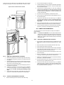
4.3- DOWN FLOW ORIENTATION
To install. the furnace in down flow position, few steps are needed for
proper operation
NOTE: It is STRONGLY RECOMMENDED to use the optional downflow base
to ensure the 2’’ clearance around the supply duct going through
the floor and the proper leveling of the furnace for condensate
drainage. Also, the base allows sufficient spacing for the venting
and the drain trap.
4.3.1- Down flow condensate drain connection
1. Remove all PVC tubes from the ID blower, condensate box and
vent collector and block the stubs with furnished 5/8’’ & 1/2’’ black
caps.
2. Remove the knock-out from the bottom left side of the casing.
3. Place the drain trap gasket on drain trap.
4. Install the drain trap on the bottom left side, the three outlet stubs
of the drain trap toward the interior of the furnace. The three
outward stubs ends are now inside the furnace.
5. Screw in place the drain trap with 2 head tapping screws on the
side of the furnace.
6. Cut 20’’ of furnished 5/8’’ clear PVC tube and connect one end
on the port on the lower right side of the condensate box.
7. Install two 1/2’’ black plastic cap on the 1/2” stub of the drain trap.
See Figure 7 : Down flow orientation
8. Connect the other end to 5/8’’ stub of the drain trap and secure
the tube on the gas manifold with a tie wrap.
9. Connect the outlet drain from the drain trap to an additional
condensate piping in compliance with the local building codes;
that is a code approved drain, or to a condensate pump approved
for use with acidic furnace condensate.

13
Figure 7 : Down flow orientation
4.3.2- Downflow venting drainaged
All furnace with horizontal exhaust vent piping must have a drain tee
assembly and trap installed in the exhaust pipe as close to the furnace as
possible.
4.3.3- Condensate box pressure switch
The 3/16 stub just beside the drain of the condensate box must be drilled
or cut open. The PVC tubing of the pressure switch -0.2 (nearest to the ID
blower) must be connected to this stub.
Figure 8 Condensate pressure switch
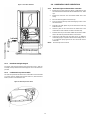
4.4- HORIZONTAL RIGHT ORIENTATION
4.4.1- Horizontal right condensate drain connection
1. Remove all PVC tubes from the ID blower, condensate box and
vent collector and block the stubs with furnished 5/8’’ & 1/2’’ black
caps.
2. Remove the knock-outs from the bottom middle side of the
casing.
3. Place the drain trap gasket on the drain trap.
4. Screw in place the drain trap with 2 head tapping screws on the
side of the furnace.
5. Install two 1/2” black plastic cap on the stubs of the drain trap
inside the furnace.
6. Connect a piece of 5/8’’ PVC tube to the bottom left of the
condensate box and route with an elbow to the drain trap.
7. Install the drain trap on the bottom middle side, the three outlets
stubs of the drain trap toward the interior of the furnace.
8. Connect the outlet drain from the drain trap to an additional
condensate piping in compliance with the local building codes or
to a condensate pump approved for use with acidic furnace
condensate.
NOTE : The drain trap must be vertical.

14
Figure 9 Horizontal right drain trap position
Figure 10 Horizontal right condensate tubing
4.4.2- Horizontal right vent drainage
All furnace with horizontal exhaust vent piping must have a drain tee
assembly and trap installed in the exhaust pipe as close to the furnace as
possible (See Figure 10 Horizontal right condensate tubing).
4.4.3- Condensate box pressure switch
The 3/16 stub just beside the drain of the condensate box must be drilled
or cut open. The PVC tubing of the pressure switch -0.2 (nearest to the ID
blower) must be connected to this stub.
The pressure switch needs now to be electrically connected in series with
the low fire pressure switch (top) with the brown jumper. See Figure 11
Pressure switch assembly and wiring diagrams.
Figure 11 Pressure switch assembly
4.5- HORIZONTAL LEFT ORIENTATION
4.5.1- Horizontal left condensate drain connection
1. Remove the knock-outs from the bottom middle side of the
casing.
2. Drill open the bottom stub of the ID blower if not already open.
Be sure to remove all debris.
3. Reroute the ID blower drain tube from the bottom of the ID blower
casing to one of the 1/2” stub. Do not screw the drain trap to
the furnace casing.
4. Block the other open ID blower drain with a 1/2’’ black cap.
5. Reroute the condensate box drain tube from the bottom of the
condensate box through the casing.
6. Reroute de vent collector drain tube to one of the 1/2” stub.
7. Apply the neoprene 7/8’’ gasket around the 5/8’’ and 1/2” tubes
at the point where they cross the furnace casing to seal the
passage.
8. Plug the 5/8’’ and 1/2” tubes to the drain trap, securing the
connections with the clamps. The drain trap must be vertical.
9. Connect the outlet drain from the drain trap to an additional
condensate piping in compliance with the local building codes; or
to a condensate pump approved for use with acidic furnace
condensate.

15
Figure 12 Horizontal left condensate drain connection
4.5.2- Condensate box pressure switch
The 3/16” stub just beside the drain of the condensate box must be drilled
or cut open. The PVC tubing of the pressure switch nearest to the ID
blower must be connected to this stub.
The pressure switch needs to be electrically connected in series with the
low fire pressure switch (top) with the brown jumper. See Figure 11
Pressure switch assembly and wiring diagrams.
5- DUCT INSTALLATION
5.1- RETURN AIR CONNECTIONS
The return air duct must be connected to bottom, left side and/or right side
NOTE: In downflow configuration, side return air is not permitted, it must
be connected to bottom.
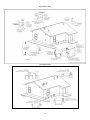
Figure 13 Return air base
5.1.1- Bottom return air inlet
In Upflow orientation, for the bottom inlet, it is possible to use a return air
base. This base allows the connection of the duct on the side with a bottom
inlet. (See Figure 13 Return air base)
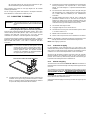
1. Cut a rectangular opening on the bottom plate of the furnace. To
know what dimension to be used, refer to the input of the furnace
as showed on Figure 4 Dimensional drawing. Install the return
air inlet as per local codes.
5.1.2- Side return air inlet
1. Remove 4 knock-outs on the side of the furnace on 8 knock-outs
available. Use the knock-outs related to the furnace size as
shown on Figure 4 Dimensional drawing. This concerns the width
of the return outlet.
2. Install the return air inlet as per local codes.
5.2- FILTER ARRANGEMENT
There are no provisions for an internal filter rack in these furnaces. An
external filter is required.
5.3- SUPPLY AIR DUCTS
The supply air duct must be connected ONLY to the furnace supply outlet
air duct flanges or air conditioning coil casing (when used). DO NOT cut
main furnace casing side to attach supply air duct, humidifier, or other
accessories. All accessories MUST be connected to duct external to
furnace main casing.
NOTE: Many states, provinces and localities are considering or have
implemented standards and/or restrictions on duct sizing
practices, ductwork leakage, and/or ductwork thermal, airflow and
electrical efficiencies. CONSULT LOCAL CODE OFFICIALS for
ductwork design and performance requirement in your area.
5.4- GENERAL REQUIREMENTS
The duct system should be designed and sized according to accepted
national standards such as those published by: Air Conditioning
Contractors Association (ACCA), Sheet Metal and Air Conditioning
Contractors National Association (SMACNA) or American Society of
Heating, Refrigerating and Air Conditioning Engineers (ASHRAE) or
consult The Air Systems Design Guidelines reference tables available
from your local distributor.

16
The duct system should be sized to handle the required system design
CFM at the design external static pressure. The furnace airflow rates are
provided in CFM tables at the end of this manual. When a furnace is
installed so that the supply ducts carry air circulated by the furnace to
areas outside the space containing the furnace, the return air shall also be
handled by duct(s) sealed to the furnace casing and terminating outside
the space containing the furnace.
Secure ductwork with proper fasteners for type of ductwork used. Seal
supply and return duct connections to furnace with code approved tape or
duct sealer.
NOTE: Flexible connections can be used between ductwork and furnace
to prevent transmission of vibration.
Ductwork passing through unconditioned space should be
insulated to enhance system performance. When air conditioning
is used, a vapour barrier is recommended.
Maintain a 1 in. (25 mm) clearance from combustible materials to
supply air ductwork for a distance of 36 in. (914 mm) horizontally
from the furnace. See NFPA 90B or local code for further
requirements.
5.4.1- Duct work acoustical treatment
Metal duct systems that do not have a 90 degree elbow and 10 ft. (3 M)
ofmain duct to the first branch take-off may require internal acoustical
lining. As an alternative, fibrous ductwork may be used if constructed and
installed in accordance with the latest edition of SMACNA construction
standard on fibrous glass ducts. Both acoustical lining and fibrous
ductwork shall comply with NFPA 90B as tested by UL Standard 181 for
Class 1 Rigid air ducts.
NOTE: For horizontal applications, the top most flange may be bent past
90° to allow the evaporator coil to hang on the flange temporarily
while the remaining attachment and sealing of the coil are
performed.
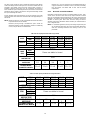
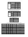
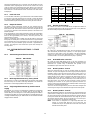
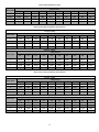
Table 3 Air flow capacity and blower data 2 stage variable
INPUT
HIGH
45,000
60,000
75,000
105,000
120,000
LOW
31,500
42,000
52,500
73,500
84,000
OUTPUT
HIGH
42,750
57,000
71,475
99,750
115,080
LOW
29,925
39,900
50,032
69,825
80,556
EFFICIENCY
95
95
95.3
95
95.9
TEMP. RISE
40-70 °F
MAX
CFM
HIGH
Please see tables in Annex I
LOW
COOLING
DIRECT DRIVE
MOTOR TYPE
ECM
DIRECT DRIVE
MOTOR HP
1/2
3/4
3/4
1
1
BLOWER WHEEL
DIAMETER X WIDTH
11 x 6
11 x 8
11 x 9
11 x 11
11 x 11
Table 4 : Air flow capacity and blower data 2 stage direct drive
INPUT
HIGH
45,000
60,000
75,000
105,000
120,000
LOW
31,500
42,000
52,500
73,500
84,000
OUTPUT
HIGH
42,750
56,640
71,775
99,540
115,200
LOW
29,925
39,648
50,242
69,678
80,640
EFFICIENCY
95
94.4
95.7
94.8
96
TEMP. RISE
40-70 °F
MAX
CFM
HIGH
Please see tables in Annex I
LOW
COOLING
DIRECT DRIVE
MOTOR TYPE
PSC
DIRECT DRIVE
MOTOR HP
1/2
1/2
3/4
1
1
BLOWER WHEEL
DIAMETER X WIDTH
11 x 6
11 x 8
11 x 9
11 x 11
11 x 11

17
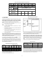
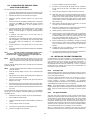
Table 5 : Air flow capacity and blower date 1 stage direct drive
INPUT
HIGH
45,000
60,000
75,000
105,000
120,000
OUTPUT
HIGH
42,750
57,000
71,475
100,065
115,440
EFFICIENCY
95
95
95.3
95.3
96.2
TEMP. RISE
40-70 °F
MAX
CFM
HIGH
Please see tables in Annex I
COOLING
DIRECT DRIVE
MOTOR TYPE
PSC
DIRECT DRIVE
MOTOR HP
1/2
1/2
3/4
1
1
BLOWER WHEEL
DIAMETER X WIDTH
11 x 6
11 x 8
11 x 9
11 x 11
11 x 11
6- GAS PIPING
Gas piping must be installed in accordance with national and local codes.
Refer to current edition of NFGC in the U.S.A. Refer to current edition of
CAN/CSA B149.1 in Canada. Installations must be made in accordance
with all authorities having jurisdiction. If possible, the gas supply line
should be a separate line running directly from meter to furnace.
NOTE: Use a back-up wrench on the inlet of the gas valve when
connecting the gas line to the gas valve.
NOTE: In the state of Massachusetts:
1. Gas supply connections MUST be performed by a licensed
plumber or gas fitter.
2. When flexible connectors are used, the maximum length shall
not exceed 36 in. (915 mm).
3. When lever handle type manual equipment shutoff valves are
used, they shall be "T" handle valves.
4. The use of copper tubing for gas piping is NOT approved by the
state of Massachusetts.
Report to Table 6 Maximum capacity of pipe for recommended gas pipe
sizing. Support all gas piping with appropriate straps, hangers, etc. Use a
minimum of 1 hanger every 6 ft (1.8 m). Joint compound (pipe dope)
should be applied sparingly and only to male threads of joints. Pipe dope
must be resistant to the action of propane gas.
An accessible manual equipment shut off valve MUST be installed
external to furnace casing and within 6 ft. (1.8 m) of furnace.
Install a sediment trap in riser leading to furnace as shown in Figure 14
Typical gas pipe arrangement. Connect a capped nipple into lower end of
tee. Capped nipple should extend below level of furnace gas controls.
Place a ground joint union between furnace gas control valve and exterior
manual equipment gas shutoff valve.
Table 6 Maximum capacity of pipe in Ft³ of gas/hr
Nominal
Iron pipe
size in.
(mm)
Internal dia.
in. (mm)
Length of pipe - FT (M)
10 (3.0)
20 (6.0)
30 (9.1)
40
(12.1)
50
(15.2)
1/2 (13)
0.622 (158)
175
120
97
82
73
3/4 (19)
0.824 (20.9)
360
250
200
170
151
1 (25)
1.049 (26.6)
680
465
375
320
285
1-1/4 (32)
1.380 (35.0)
1400
950
770
660
580
1-1/2 (39)
1.610 (40.9)
2100
1460
1180
990
900
* Cubic feet of gas per hr for gas pressures of 0.5 psig (14 in. w.c)
(Based on a 0.60 specific gravity gas)
Ref: Table 6.2 of NFPA54/ANSI Z223.1-2009
Figure 14 Typical gas pipe arrangement
A 1/8” (3 mm) NPT plugged tapping, accessible for test gauge connection,
MUST be installed immediately upstream of gas supply connection to
furnace and downstream of manual equipment shutoff valve.
Piping should be pressure and leak tested in accordance with the current
addition of the NFGC in the United States, local, and national plumbing
and gas codes before the furnace has been connected. Refer to current
edition of NSCNGPIC in Canada. After all connections have been made,
purge lines and check for leakage at furnace prior to operating furnace.
NOTE: The furnace gas control valve inlet pressure tap connection is
suitable to use as test gauge connection providing test pressure.
Table 7 Gas pressure
Gas Pressure in w.c.
(psig)
Natural gas
Propane
Maximum
10.5 (0.38)
13.0 (0.47)
Minimum
4.5 (0.16)
11.0 (0.40)
If pressure exceeds 0.38 psig (10.5 in. W.C.), gas supply pipe must be
disconnected from furnace and capped before and during supply pipe
pressure test. If test pressure is equal to or less than 0.38 psig (10.5 in.
W.C.), turn off electric shutoff switch located on furnace gas control valve
and accessible manual equipment shutoff valve before and during supply
pipe pressure test. After all connections have been made, purge lines and
check for leakage at furnace prior to operating furnace.

18
The gas supply pressure shall be within the maximum and minimum inlet
supply pressures marked on the rating plate with the furnace burners and
in Table 7 Gas pressure.
6.1- GAS PIPE GROMMET
For direct vent (2 pipes) applications, the hole for the gas pipe on the
cabinet must be sealed to prevent air leakage. Install the grommet in the
hole, then insert the gas pipe and apply fillet paste.
7- ELECTRICAL CONNECTIONS
WARNING
FIRE HAZARD
Failure to follow this warning could result in personal injury, death, or
property damage.
Do not connect aluminium wire between disconnect switch and
furnace. Use only copper wire.
Check all factory and field electrical connections for tightness.
Supplied field wiring shall conform to the limitations of 63°F (33°C) rise.
7.1- 120 V WIRING
Furnace must have a 120 V power supply properly connected and
grounded.
NOTE: Proper polarity must be maintained for 120 V wiring. If polarity is
incorrect, control LED status indicator light will flash rapidly and
furnace will NOT operate.
Verify that the voltage, frequency, and phase correspond to that specified
on unit rating plate. Also, check to be sure that service provided by utility
is sufficient to handle load imposed by this equipment. Refer to rating plate
or Table 8 Electrical data for equipment electrical specifications.
U.S.A. Installations:
Make all electrical connections in accordance with the current edition of
the National Electrical Code (NEC) ANSI/NFPA 70 and any local codes or
ordinances that might apply.
Canada Installations:
Make all electrical connections in accordance with the current edition of
the Canadian Electrical Code CSA C22.1 and any local codes or
ordinances that might apply.
Use a separate, fused branch electrical circuit with a properly sized fuse
or circuit breaker for this furnace. See Table 8 Electrical data for wire size
and fuse specifications. A readily accessible means of electrical
disconnect must be located within sight of the furnace.
.
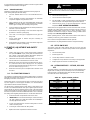
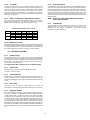
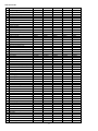
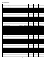
Table 8 Electrical data
Max. Min.
45 000 120-60-1 127 104 10.7 12,6 14 29 (8.8) 15
60 000 120-60-1 127 104 13.1 15,6 12 36 (11.0) 20
75 000 120-60-1 127 104 13.1 15,6 12 36 (11.0) 20
105 000 120-60-1 127 104 15.8 19 12 36 (11.0) 20
120 000 120-60-1 127 104 15.8 19 12 36 (11.0) 20
Max. Min.
45 000 120-60-1 127 104 10.7 12.6 14 29 (8.8) 15
60 000 120-60-1 127 104 12.6 15 14 29 (8.8) 15
75 000 120-60-1 127 104 12.6 15 14 29 (8.8) 15
105 000 120-60-1 127 104 15.8 19 12 36 (11.0) 20
120 000 120-60-1 127 104 15.8 19 12 36 (11.0) 20
Max. Min.
45 000 120-60-1 127 104 12.8 15.3 14 36 (11.0) 20
60 000 120-60-1 127 104 12.5 14.9 12 29 (8.8) 15
75 000 120-60-1 127 104 12.5 14.9 14 29 (8.8) 15
105 000 120-60-1 127 104 15.8 19.1 12 36 (11.0) 20
120 000 120-60-1 127 104 15.8 19.1 12 36 (11.0) 20
Max. Min.
45 000 120-60-1 127 104 13.4 15.9 12 36 (11.0) 20
60 000 120-60-1 127 104 13.1 15.5 12 36 (11.0) 20
75 000 120-60-1 127 104 13.1 15.5 12 36 (11.0) 20
105 000 120-60-1 127 104 16.4 19.6 12 36 (11.0) 20
120 000 120-60-1 127 104 16.4 19.6 12 36 (11.0) 20
1 stage PSC motor
Unit Size
Volts-Hertz-
Phase
Operating Voltage
Range
Maximum
Unit Amps
Unit
Ampacity
Minimum
Wire Size
AWG
Maximum
Wire Length
Ft( m)
Maximum Fuse
or CKT BKR
Amp
2 stage PSC motor
Unit Size
Volts-Hertz-
Phase
Operating Voltage
Range
Maximum
Unit Amps
Unit
Ampacity
Minimum
Wire Size
AWG
Maximum
Wire Length
Ft( m)
Maximum Fuse
or CKT BKR
Amp
2 stage variable speed
Unit Size
Volts-Hertz-
Phase
Operating Voltage
Range
Maximum
Unit Amps
Unit
Ampacity
Minimum
Wire Size
AWG
Maximum
Wire Length
Ft( m)
Maximum Fuse
or CKT BKR
Amp
Modulating furnace
Unit Size
Volts-Hertz-
Phase
Operating Voltage
Range
Maximum
Unit Amps
Unit
Ampacity
Minimum
Wire Size
AWG
Maximum
Wire Length
Ft( m)
Maximum Fuse
or CKT BKR
Amp

19
Figure 15 Power cord installation in the furnace
7.2- 24 V WIRING
Make field 24 V connections at the 24 V terminal strip. Connect terminal
Y/Y2 for proper cooling operation. Use only AWG No. 18, color-coded,
copper thermostat wire.
NOTE: Use AWG No. 18 color coded copper thermostat wire for lengths
up to 100ft. (30.5m). For wire lengths over 100 ft., use AWG No
16 wire.
The 24 V circuit contains an automotive type, 3-amp fuse located on the
control. Any direct shorts during installation, service, or maintenance could
cause this fuse to blow. If fuse replacement is required, use ONLY a 3
amp.
7.3- THERMOSTATS
Thermostats and Control Settings for Two Stage Furnaces.
A single stage or two stage heating and single stage or two stage cooling
thermostat may be used with the furnace. Consult the thermostat
installation instructions for specific information about configuring the
thermostat.
Thermostats and Control Settings for Single Stage furnaces.
A single stage heating and single stage or two stage cooling thermostat
may be used with the furnace. Consult the thermostat installation
instructions for specific information about configuring the thermostat.
7.4- ALTERNATE POWER SUPPLY
The furnace is designed to operate on utility generated power which has
a smooth sinusoidal waveform. If the furnace is to be operated on a
generator or other alternate power supply must produce a smooth
sinusoidal waveform for compatibility with the furnace electronics. The
alternate power supply must generate the same voltage, phase, and
frequency (Hz) as shown in or the furnace rating plate.
Power from an alternate power supply that is non-sinusoidal may damage
the furnace electronics or cause erratic operation.
Contact the alternate power supply manufacturer for specifications and
details.
7.5- BLOWER SPEEDS (4 SPEED PSC MOTOR)
Furnace with model number CXX-1-D and CXX-2-D are equipped with a
multi-speed circulator blower. This blower provides ease in adjusting
blower speeds. See airflow tables in annexe for the relation between CFM
and external static pressure applicable to your model. The cooling and
heating blower speed are shipped with the suggested fan speed describe
in table 9 and table 10. These blower speeds are set for a temperature
rise of 55°F. Blowers should be adjusted by the installer to match the
installation requirements so as to provide the correct heating temperature
rise and cooling load. To adjust the circulator blower speed, proceed as
follow:
1. Turn off the power to the furnace
2. Select the heating and cooling blower speeds that match the
installation requirements from the airflow tables in annexe.
3. Relocate the desired motor leads to the desire speed on the
motor.
4. If heating and cooling speeds are the same, a jumper wire must
be used between the heat and cool terminal on the control
board. The unused leads must be connected to the “PARK”
terminal on the control board.
5. Turn on power to the furnace.
6. Verify proper temperature rise. Excessive temperature rise can
cause limit switch tripping.
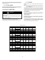
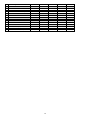
Table 9 : Suggested fan speed on 1 stage furnace
INPUT
HEATING
COOLING
45,000
LOW
MED-HIGH
60,000
MED-LOW
MED-HIGH
75,000
MED-LOW
MED-HIGH
105,000
HIGH
MED-HIGH
120,000
HIGH
MED-HIGH
Table 10 : Suggested fan speed on 2 stage furnace
INPUT
HEATING 1st
STAGE
HEATING 2nd
STAGE
COOLING
45,000
LOW
MED-LOW
MED-HIGH
60,000
LOW
MED-LOW
MED-HIGH
75,000
LOW
MED-LOW
MED-HIGH
105,000
LOW
MED-HIGH
MED-LOW
120,000
MED-LOW
HIGH
MED-HIGH

20
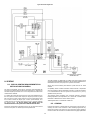
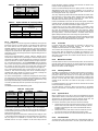
Figure 16 Wiring diagram – One stage PSC
Page is loading ...
Page is loading ...
Page is loading ...
Page is loading ...
Page is loading ...
Page is loading ...
Page is loading ...
Page is loading ...
Page is loading ...
Page is loading ...
Page is loading ...
Page is loading ...
Page is loading ...
Page is loading ...
Page is loading ...
Page is loading ...
Page is loading ...
Page is loading ...
Page is loading ...
Page is loading ...
Page is loading ...
Page is loading ...
Page is loading ...
Page is loading ...
Page is loading ...
Page is loading ...
Page is loading ...
Page is loading ...
Page is loading ...
Page is loading ...
Page is loading ...
Page is loading ...
Page is loading ...
Page is loading ...
Page is loading ...
Page is loading ...
Page is loading ...
-
 1
1
-
 2
2
-
 3
3
-
 4
4
-
 5
5
-
 6
6
-
 7
7
-
 8
8
-
 9
9
-
 10
10
-
 11
11
-
 12
12
-
 13
13
-
 14
14
-
 15
15
-
 16
16
-
 17
17
-
 18
18
-
 19
19
-
 20
20
-
 21
21
-
 22
22
-
 23
23
-
 24
24
-
 25
25
-
 26
26
-
 27
27
-
 28
28
-
 29
29
-
 30
30
-
 31
31
-
 32
32
-
 33
33
-
 34
34
-
 35
35
-
 36
36
-
 37
37
-
 38
38
-
 39
39
-
 40
40
-
 41
41
-
 42
42
-
 43
43
-
 44
44
-
 45
45
-
 46
46
-
 47
47
-
 48
48
-
 49
49
-
 50
50
-
 51
51
-
 52
52
-
 53
53
-
 54
54
-
 55
55
-
 56
56
-
 57
57


Chinook c60-2-v Installation Manual And Owner's Manual
- Type
- Installation Manual And Owner's Manual
- This manual is also suitable for
Ask a question and I''ll find the answer in the document
Finding information in a document is now easier with AI
Other documents
-
Dettson Modulating Chinook (M-V, M-S) Installation guide
-
Amana GMV9 Installation Instructions Manual
-
-
York GY8S-E Installation guide
-
International comfort products N9MSE0401712A Installation guide
-
-
 GOODMAN GCV9 Series Installation & Operating Instructions Manual
-
ICP F9MVT0601714A1 Installation guide
-
-
Trane BAYFTFR17M2 Installation guide
