
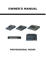
OWNER'S MANUAL
PROFESSIONAL MIXER

Index
Before operating,please read this manual completely.
Specifications . . . . . . . . . . . . . . . . . . . . . . . . . . . . . . . . . . . . . . . . . . . . . . . . . 1
Input Module. . . . . . . . . . . . . . . . . . . . . . . . . . . . . . . . . . . . . . . . . . . . . . . . . . 2
Stereo Input Module. . . . . . . . . . . . . . . . . . . . . . . . . . . . . . . . . . . . . .. . . . . . . 5
Master Section. . . . . . . . . . . . . . . . . . . . . . . . . . . . . . . . . . . . . . . .. . . . . . . . . . 6
Effect . . . . . . . . . . . . . . . . . . . . . . . . . . . . . . . . . . . . . . . . . . . . . . . . . . . . . . . 7
Meter Pod. . . . . . . . . . . . . . . . . . . . . . . . . . . . . . . . . . . . . . . . . . . . . . . . . . . . . 8
Output Connectors. . . . . . . . . . . . . . . . . . . . . . . . . . . . . . . . . . . . . . . . . . . . . . 9
Power. . . . . . . . . . . . . . . . . . . . . . . . . . . . . . . . . . . . . . . . . . . . . . . . . . . . . . . 10
Rear Panel . . . . . . . . . . . . . . . . . . . . . . . . . . . . . . . . . . . . . . . . . . . . . . . . . . . . 10
System Connection . . . . . . . . . . . . . . . . . . . . . . . . . . . . . . . . . . . . . . . . . . . . . 11
Usually Set Up. . . . . . . . . . . . . . . . . . . . . . . . . . . . . . . . . . . . . . . . . . . . . . . . . 14
System Diagram. . . . . . . . . . . . . . . . . . . . . . . . . . . . . . . . . . . . . . . . . . . . . . . . 15
Safety Precautions. . . . . . . . . . . . . . . . . . . . . . . . . . . . . . . . . . . . . . . . . . . . . . 15
Specifications
Maximum Output Level: 19dBm (1KHz, THD=0.5%)
Residual Noise: -75dB
Signal to Noise Ratio: 71dB
Equivalent Input Noise:-12dBm
Equivalent Input Noise:-120dBm
Headphone Power:40mw (1 KHz, THD=0.5%, 200Ω)
Equalization:
Low:80Hz±15dB
Mid:2.5KHz±15dB
High:12KHz±15dB
Gain Control:
Mono:-55dB~0dB
Stereo:-10dB~0dB
Frequency Response:20Hz~20 KHz (+1dB,-3dB)
THD+N:≤0.05%(1KHz,0.775V)
Power Input: AC220v~240V/50~60Hz
Dimensions: 400mmx400mmx45mm

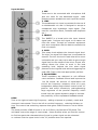
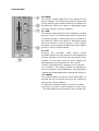
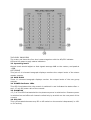
Input Module
1. MIC
These are to be connected with microphone XLR
jack are used for the balancedd signal. +48V
phantom power available on each input Mic socket.
2. LINE
The unbalanced mic input is provided for the use of
a unbalancedd mic and is designed to accept a
unbalanced high impedance input signal. (This
used for connection Deck, Turntable and Keyboard
etc.)
3. INSERT
The INSERT is a bread point the input channel
signal path. It allows the signal to be taken out
from the mixer. Through an external equipment
such as a compressor and the back to continue the
final mix output.
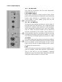
4. GAIN
This rotary knob adjusts the channel signal level.
Too high: the signal will distort as it overloads the
channel. Too low: the level if back hiss will be more
noticeable and you may not be able to get enough
signal level to the output of the mixer. Proper trim
setting allows the mixer to work in the best
operating level. Adjusts the trim when signal
presents to the highest level without triggering the
peak LED. That is the most appropriate position.
5. EQUALIZERS
These equalizers are designed to suit different
room acoustics,feedback control and improve the
live PA sound. No amount of equalization will
correct the frequency response curve of a poor
loudspeaker. Always begin with all control in the “O”
position and avoid excessively cutting/boosting
large segments of the peculiar frequency which
would limit the system dynamic range or increase
the possibility of the unpleasant feedback sound.
HIGH
Turn to the right to boost high frequency,adding crispness to cymbals, vocals and
electronic instruments. Turn to the left to cut this frequency,reducing sibilance or
hiss. The control has a shelving response that gives 15dB of boost or cut at 12KHz.
MID
The knob provides 15dB of boost or cut at 2.5kHz. just like the HF EQ knob. The
mid band covers the range of most vocals,listen carefully when you use this control
to find how particular characteristics of vocal or guitar signal can be enhanced
or reduced. Set the upper knob in the “O” position when not required.

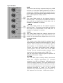
Input Module
LOW
The control has shelving response that giving 15dB
of boost or Cut at 80Hz. Adding warmth to vocals or
extra punch to guitars. drums and synths but turn
to the right, turn to the left to reduce stage rumble,
hum or to improve a mushy sound.
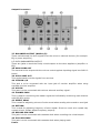
6. AUX l
This rotary fader sends out the channel signal to
auxiliary bus 1. The signal is ere-fader So that the
aux send 10 be independent of the fader: this is
suitable for feedback or monitor.
AUX 2
This rotary fader sends out the channel signal Io
auxiliary bus 2. The signal is pre-fader so that the
aux send to be independent of the fader, this is
suitable for feedback or monitor.
7. EFF
This rotary fader feeds the channel signal to the
external effect the signal is post fader. This is very
helpful for simultaneously adjust the level of the
processed signal.
8. PAN
This rotary control determined the assignment of
signal forth the channel to left and right or 1 and 2
groups. When the pan pot is set centrally signal is
sent equally to all selected groups and master.
Turning the control anticlockwise send relatively
more signal to the left master and to the SUB1
Turning the pot clockwise sends relatively more
signal to the right master and to SUB2. The
pan pot may thus be used to adjust the position of
signals in the stereo image.
9. PEAK
This red LED (light emitting diode) illuminates
when the channel approaches an overload
situation. the LED is activated 3dB before the
onset of clipping (distort). The input GAIN control
should be adjusted So that the LED does not flash
except on the highest level. brief transients. Using
excessive amounts of boots on the channel
equalizer may cause distortion on the channel:if
this happens turn the input GAIN control down.

Input Module
10. MAIN
This switch routes signal form the channel to the
stereo masters. The relative amounts of signal sent
to the left and right is determined by the position of
the PAN pot. When the switch is depressed signal
from the channel is sent to masters.
11. SUB
This switch routes signal firm the channel to output
groups 1 and 2. The relative amounts of signal sent
to the two groups is determined by the position of
the PAN pot. When the switch is depressed signal
from the channel is sent to groups 1 and 2. When
the switch is in the raised position the signal feed to
groups 1 and 2 is disconnected.
12. PFL
Pressing this Pre-Fader listen switch routes
pre-fader signal from the channel to the headphone
monitor outputs on the front and rear panels of the
console. At the same time all other signals are
automatically disconnected from the monitor
Section, allowing the PFL signal(s) to be listened
to in isolation. This feature allows the operator to
listen to a signal on the headphone, checking that it
is dean and undistorted before fading the signal up.
13. FADER
The channel fader is a 60mm travel audio fader. Is
adjusts the level of signal sent from the channel to
the groups, stereo masters.
To allow the optimum tangle of control the fader
should be run close to the O position on the scale.
The input GAIN control should be set to allow this.

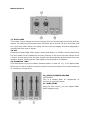
Stereo Input Module
14. L /R PIN JACK
This used for connection into line level equipment.
(Tape machines etc.)
L/R STEREO INPUT
These light impedance inputs accept 2-pole phone
jacks. Use these inputs for keyboards, drum machines,
synths, tape machine or processing units, if the
source signal is mono please plugs into the left
channel socket only.
15. -10 /+4 SWITCH
The stereo input channel accepts 1/4" phone jacks. It
provides two input sensitivities. The -10dH should be
selected for amateur type machine or HIFI systems,
most professional equipment user input and output
level of +4dB. This switch allows you to match the
sources connected to the stereo input channel to
either standard, which is important to ensure the best
possible sound quality, start with the switch +4, if you
can't achieve an enough signal level, select to -10dB.
16. HIGH
The control has shelving response that giving 15dB of
boost or cut at 80Hz. Adding warmth to vocals or extra
punch to guitars, drums and synths bu turn to the
right, turn to the left to reduce stage rumble, humor
to Improve a mushy sound.
LOW
Turn to the right to boost high frequency, adding crisp-
ness to cymbals, vocals and electronic instruments.
Turn to the left to cut this frequency, reducing
sibilance or hiss. The control has a shelving response
that gives 15dB of boost or cut at 12 KHz.

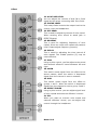
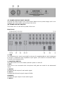
Master Section
17. AUX1 AUX2
This rotary control adjusts the level of signal sent for, the auxiliary bus to the auxiliary
output. For optimum performance this should be set to around 7or 8 on the scale, and
the input level often effects unit being fed from the aux output should be adjusted to
operate with this level of signal.
18. AFL
Pressing this after fader listen switch routes post-fader (i.e. LEVEL control) signal form
the aux master to the headphone monitor outputs on the front and rear panels of the
console. At the same time all other signals are automatically disconnected form the
monitor section, allowing the A Fled signal to be listened to in isolation.
19. PHANTOM +48V
This slide-switch turns the master phantom power on and off. 1-2, 3-4 is applies 48V
DC across I-2 and 3-4 each microphone input channels connectors for remote powering
of condenser microphones.
20. OUTPUT MASTER FADERS
LEFT/RIGHT
This is a master fader for adjustment of
volume of right/left output.
21. SUB1/SUB2
Using by this control, you can adjust SBUI,
SBU2 outputs level.

Effect
22. AUX TAPE LEVEL
You con adjust the volume of AUX IN or PLAY
signal by this when connecting AUX IN or PLAY.
23. PHONE LEVEL
This rotary fader controls the output level to the
control room and headphone.
24. EFF SEND
This is used for adjusting volume of echo sound.
When sending echo sound to wend jack in
EFFECTS panel.
25. REAPEAT
This is used for adjusting frequency of echo
repeat. Since too much echo repeat may cause a
howl. Please adjust frequency properly.
26. DELAY
This is used for adjusting the time interval of
echo repeat. The middle position (5) may be
most effective.
27. PAN
Using by this control, you fan adjust echo sound
and external effectors’ sound between left and
right.
28. MAIN
This switch routes signal form the effect to the
stereo master, when the switch is depressed
signal from the channel is sent to masters.
29. SUB
This switch routes signal form the effect to
groups 1 and 2. When the switch is depressed
signal from the channel is sent to group 1 and 2.
30. EFFECT FADER
Using by this control. you can adjust signal level
of echo repeat and external effectors’ volume.
31. PFL
When you want to monitor echo sound and
external effectors’ sound, you can adjust this
control through the headphone.
Meter Pod

THE LEVEL INDICATOR
The meter pod hoses the four level meters together with the AFL/PFL indicator
LED and the power supply status indicators.
32. Operating levels
Output levels should adjust so that signals average 0dB on the meters, and peak at
+3dB.
LEFT/RIGHT
This pair of 10 element barograph displays monitors the output levels of the stereo
master outputs.
33. SUBI SUB2
These 10 element barograph displays monitor the output levels of the two group
outputs.
34. POWER Indicator LEDs
This LED illuminates whim the console is switched in and indicates the status often +
and -17 volt DC power rails of the console.
35. PHANTOM
1-2, 3-4 This LED illuminated whim the phantom power is switched on. Phantom power
is switched on and offers all channels collectively by a switch on the rear panel of the
console.
36. PFL/AFL
This is illuminated whenever any PFL or AFL switch on the console is depressed (i.e. AFL
or PLF active).

Output Connectors
37. BALANCED OUTPUT (MAIN L/R)
These sockets send line level signals from the mixer to external devices (for example:
EQ or power amplifier).
L/R IACK UNBALANCEDD OUTPUT
These are jacks to send the finally mixed outputs to the other appliance (amplifier or
EQ).
38. SUB1 SUB2 OUT
The terminal to be output with the volume control against inputting signal into SUB l-2
board.
39. AUX1 AUX2 OUT
This socket sends out the signals from aux bus.
40. CTRLRM L/R
This jack is to be connected with the input jack of monitor amplifier when using
separate monitor amplifier.
41. AUX IN
This jack is to be connected with various external auxiliary signal.
42. PHONES JACK
This is used for monitoring the master signal and individually monitoring each channel
with PEL/AFL switch.
43. EFFECT SENG
This is used for adjusting volume of echo sound when sending echo sound to send jack
44. RETURN
This is used for adjusting frequency of echo repeat. Since too much echo repeat may
caused a howl. Please adjust frequency properly.
45. RECORD PIN JACK
This jack is to be connected with cassette deck when recording the mixed output.
46. PLAY PIN JACK
This jack is to be connected with cassette deck when playing back.
Power

47. POWER SUPPLY INPUT SOCKET
Connect the power supply unit to this socket. Make sure the power supply unit is not
plugged into mains before connecting to the mixer.
48. POWER ON/OFF SWITCH
This switch turn on and off the power of the unit.
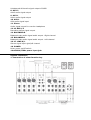
Rear Panel
1. LINE
The unbalanced mic input is provided for the use of a unbalancedd mic and is designed
to accept a unbalanced high impedance input signal. (This used for connection Deck,
Turntable and Keyboard etc.)
2. PHANTOM SWITCH
This slide-switch turns the master phantom power on and off.
3. MIC
These are to be connected with microphone XLR jacks are used for the balancedd
signal.
4. MAIN L
Unbalanced left output of main audio signal
5. AUX 3
Unbalanced AUX audio signal output of SUB1
6.MAIN R
Unbalanced right output of main audio signal
7. AUX 2

Unbalanced AUX audio signal output of SUB2
8. AUX 2
AUX2 audio signal output
9. AUX 1
AUX1 audio signal output
10. AUX 1
AUX audio signal input
11. Phone
Audio signal output for monitor headphone
12-13. REC1/2
Recording stereo signal output
14. BALANCED R
Balanced main audio signal audio output –Right channel
15. BALANCED L
Balanced main audio signal audio output –Left channel
16-17. LINE R/L
Stereo signal input right/left channel
18. POWER
Mixer power on/off switch
19:AC220V/50Hz power input jack
System connection
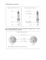
1. Connection of mixer function key

2. Connection of headset jack
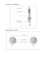
3. Balanced input connection

4. Different type of connector
Note: If balanced(TRS) jack connect to unbalanced (TS) jack, hot (+) terminal
can not connect to cold (-) terminal.

Usually Set Up
Even if you do not like to read manual, please read this section.
This procedure is very important, even if you do not like to read manual. Please read
this section. After you connected up the system, you are ready to set the initial set up
for every input channel, the matching of every input trim to the signal source is crucial.
Every detail will affect the final output of the mixer. Basically, the input sensitivity
adjustment, channel fader, groups and output fader is the main factors. You should try
to set only as much microphone trim as required to achieve good balanced between
signals. It the input gain is set too low, you will not get enough gain on the faders to
push the signal up to adequate level, if the input gain is set too high, the channel fader
will need to be pulled down in compensation, but leave the greater risk of feedback
because a small fader movements will have a very significant effect on output level.
Certainly, the limited fader travel path will not successful in the mixing procedure.
Please use the following set up procedure, do not use the old way: turning the output
up until they clip and then backing off
Follow the procedure for each channel in use
Set all faders and gain controls all the way off.
Phantom powered microphone should be connected before the+48V is switched on.
Set power amplifier level to 70%.
Set the CTRL RM level and Headphone level to about 50%.
If you want to hear what you are doing later, plug your headphone into the phone
output socket,or hook up your control room amplifier system to the Control Room
outputs.
Set EQ control at center position.
Set PAN and BALANCED knobs at center position.
You need a headphone to continue.
Apply a typical performance level signal monitoring the level on the LED meter.
Adjust the input gain until the meter show in the amber section with occasional peak
to the first red LED at maximum source level. This allows enough headroom to
accommodate peak and the maximum level for normal operation; you can listen to
them through your headphone.
For +4 line level audio signals, slide the+41-10 switch to +4.
For -10 sources. slide the +4/-10 swatch to -10.
For microphone source, the gain control adjustment will depend on what kind of the
microphone you use,normally turn the gain clockwise around 2-3 o’clock. But please
ask the singer to perform alive, do not whisper. If they did not wake up while you are
doing the sound check when they are back to alive, you might drive the mixer overload
or produce the feedback, because you Set the gain too high during the initial set up.
Most often mistakes in audio installation are incorrect and deflective audio
Repeat this procedure on every other channel, when more channels are added to the
mixer. the meters LED may move up to the red section。adjust the overall level using
the Pilaster faders if necessary.

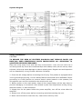
System Diagram
Safety Precautions
CAUTION:
TO REDUCE THE RISK OF ELECTRIC SHOCK.DO NOT REMOVE COVER (OR
BACK).NO USER SERVICEABLE PARTS INSIDE.REFER ALL SERVICING TO
QUALIFIED SERVICE PERSONNEL.
Keep this mixer away from dust anti dirty environment:cover the unit whit not in
use.Using a soft dry brush anti occasional wipe with a damp cloth, do not use any other
solvents, which may cause damage to paint or plastic parts. Regular rare and inspection
will be rewarded by a long life and maximum reliability.
1. Check the AC voltage before connecting the AC plug. This product is equipped with a
3-wire grounding type plug;this is a safety feature and should not be defeated. Proper
grounding is a must practice to prevent electric shock hazard to the operator, the
microphone user and the musicians who wired to this unit.
2. Before switch on the main power, keep all the output faders all the way down to
prevent damaging or excessive noise caused by bad level adjustment wrong wiring,
defective cables, or bad connection.
3. Always turn on the power before the power amplifier, turn off the mixer after the
amplifier.
4. Always turn off the power before connecting and disconnecting the unit.
5. Never use solvents to clean the unit, clean with a soft dry cloth.
-
 1
1
-
 2
2
-
 3
3
-
 4
4
-
 5
5
-
 6
6
-
 7
7
-
 8
8
-
 9
9
-
 10
10
-
 11
11
-
 12
12
-
 13
13
-
 14
14
-
 15
15
-
 16
16


LY International Electronics H-F12/2 Owner's manual
- Category
- Audio equalizers
- Type
- Owner's manual
Ask a question and I''ll find the answer in the document
Finding information in a document is now easier with AI
Other documents
-
soundsation ALCHEMIX 402FX User manual
-
Alto L-12 User manual
-
-
 Audiodesign PAMX3.82 Owner's manual
-
SoundCraft Spirit Live 3-2 User manual
-
-
SoundCraft MFXi Owner's manual
-
Spirit FOLIO SX mixer User manual
-
SoundCraft LX-7 II 24 Owner's manual
-
SoundCraft FX 16ii Owner's manual
