Page is loading ...

For gravity-assisted stretching and decompression
Assembly Instructions
Assemble Your
FitSpine LX
™
Inversion Table
GET STARTED
* Specifications may vary from this image and are subject to change without notice.
EN
Follow along with these instructions
OR
Scan to download the free BILT app
and search ‘Teeter’ in app.

Important Safety Instructions .................................................................................1
Items for Assembly............................................................................................2
Understanding Your Inversion Table...........................................................................3
Safety Warning Labels & Product Specifications ............................................................. 4
Assembly Steps .......................................................................................... 5 – 16
Before Inverting ............................................................................................. 17
Warranty Terms & Registration .............................................................................. 18
Terms & Conditions ...................................................................................... 20-21
Congratulations on your purchase of a Teeter FitSpine® Inversion Table!
For the best experience, it is critical that you follow the assembly instructions,
and read and fully understand the User Guide attached to the equipment
before inverting. Teeter Decompression Devices are multiple user, reusable
medical devices for home use, intended to provide traction to the spine while
stretching the para-spinal muscle and soft tissues. The devices provide non-
powered traction and are meant for use by adults.
Teeter inversion tables are FDA-Registered as 510(k) medical devices.
Indicated for:
If you have any questions concerning assembly or if any parts are missing,
DO NOT RETURN THE ITEM TO THE STORE OR CONTACT THE RETAILER.
Our dedicated product service experts can help! Contact Teeter Customer Service
at 800-847-0143, or via online forms or Live Chat at teeter.com.
Trust Teeter for unmatched quality and performance, backed by our
industry-leading warranty coverage. To register your product warranty,
go to teeter.com/Support/Warranty-Registration
• Herniated disc
• Spinal curvature due to tight muscles
• Sciatica
• Muscle spasm
• Facet syndrome
• Back pain
• Muscle tension
• Degenerative disc disease
• Spinal degenerative joint disease
• Spinal stenosis
WELCOME TO THE TEETER FAMILY
TABLE OF CONTENTS
I created Teeter so people
could live healthier and
more active lives.

SAVE THESE INSTRUCTIONS
WARNING
!
IMPORTANT SAFETY INSTRUCTIONS
READ ALL INSTRUCTIONS BEFORE USING THE INVERSION TABLE
BEFORE YOU BEGIN: Review all steps before beginning assembly and read all precautions before using the inversion table.
Carefully adhere to the Assembly Instructions and User Guide to help ensure safety and product integrity.
FAILURE TO FOLLOW INSTRUCTIONS AND WARNINGS COULD RESULT IN SERIOUS INJURY OR DEATH.
To reduce the risk of injury:
• Read and understand all the instructions, review all other accompanying documents, and inspect the equipment before using the
inversion table. It is your responsibility to familiarize yourself with the proper use of this equipment and the inherent risks of
inversion if these instructions are not followed, such as falling on your head or neck, pinching, entrapment, equipment failure, or
aggravating a pre-existing medical condition. It is the responsibility of the owner to ensure that all users of the product are fully
informed about the proper use of the equipment and all safety precautions.
• DO NOT use until approved by a licensed physician. Inversion is contraindicated in any medical or health condition that may be
made more severe by an elevation of blood pressure, intracranial pressure or mechanical stress of the inverted position, or that may
impact your ability to operate the equipment. This may include injury or illness, but also the side effects of any drug or supplement
(prescribed or over-the-counter). Specific conditions may include, but not be limited to:
· Any condition, neurological or otherwise, which results in unexplained tingling, weakness or neuropathy, seizure, sleep disorder,
lightheadedness, dizziness, disorientation, or fatigue, or impacts strength, mobility, alertness, or cognitive ability;
· Any brain condition, such as trauma, history of intracranial bleed, history or risk of TIA or stroke, or severe headaches;
· Any condition of the heart or circulatory system, such as high blood pressure, hypertension, increased risk of stroke, or use of
anticoagulants (including high doses of aspirin);
· Any bone, skeletal or spinal cord condition or injury, such as significant spinal curvature, acutely swollen joints, osteoporosis,
fractures, dislocations, medullary pins or surgically implanted orthopedic supports;
· Any eye, ear, nasal or balance condition, such as trauma, history of retinal detachment, glaucoma, optic hypertension, chronic
sinusitis, middle or inner ear disease, motion sickness, or vertigo;
· Any digestive or internal condition, such as severe acid reflux, hiatal or other hernia, gallbladder or kidney disease;
· Any condition for which exercise is specifically directed, limited or prohibited by a physician, such as pregnancy, obesity,
or recent surgery.
• ALWAYS be certain the Ankle Lock System is properly adjusted and fully engaged, and that your ankles are secure before using the
equipment. HEAR, FEEL, SEE and TEST that the Ankle Lock System is snug, close-fitting and secure EVERY TIME you use
the equipment.
• ALWAYS wear securely tied lace-up shoes with a flat sole, such as a normal tennis-style shoe.
• DO NOT wear any footwear that could interfere with securing the Ankle Lock System, such as shoes with thick soles, boots, or any
shoe that extends above the anklebone.
• DO NOT use the inversion table until it is adjusted properly for your height and body weight. Improper settings can cause rapid
inversion or make returning upright difficult. New users, and users who are physically or mentally compromised, will require the
assistance of a spotter. Make sure the equipment is set to your unique user settings prior to each use.
• DO NOT sit up or raise head to return upright. Instead, bend knees and slide your body to the foot-end of the inversion table to
change weight distribution. If locked out in full inversion, follow the instructions for releasing from the locked position before
returning upright.
• DO NOT continue using the equipment if you feel pain or become light-headed or dizzy while inverting. Immediately return to the
upright position for recovery and eventual dismount.
• DO NOT use if you are over 198 cm / 6 ft 6 in or over 136 kg (300 lb). Structural failure could occur or head / neck may impact the
floor during inversion.
• DO NOT allow children to use this machine. Keep children, bystanders, and pets away from machine while in use. The inversion
table is not intended for use by persons with reduced physical, sensory or mental capabilities, unless they are given supervision
and instruction concerning use of the machine by a person responsible for their safety.
• DO NOT store the inversion table upright if children are present. Fold and lay the table on the floor. DO NOT store outdoors.
• DO NOT use aggressive movements, or use weights, elastic bands, any other exercise or stretching device or non-Teeter®
attachments while on the inversion table. Use the inversion table only for its intended use as described in this manual.
• DO NOT drop or insert any object into any opening. Keep body parts, hair, loose clothing and jewelry clear of all moving parts.
• DO NOT use in any commercial, rental or institutional setting. This product is intended for indoor, home-use only.
• DO NOT operate equipment while under the influence of drugs, alcohol, or medication that may cause drowsiness or disorientation.
• ALWAYS inspect the equipment prior to use. Make sure all fasteners are secure.
• ALWAYS replace defective components immediately and / or keep the equipment out of use until repair.
• ALWAYS position equipment on a level surface and away from water or ledges that could lead to accidental immersion or falls.
• Refer to additional warning notices posted on the equipment. If a product label or User Guide should become lost, damaged
or illegible, contact Customer Service at 800-847-0143 for replacement.
1

A-Frame Base Assembly
with pre-assembled Angle Tether
EX1100B F51007
(LX4)
F51114
(LX5, LX6, LX7,
LX8, LX9)
T-Pin LX
Ankle Lock System
(LX4 Model Only)
FitSpine™ Table Bed Assembly
EX1300B
EX1500B
F51064 (LX4, LX5, LX6, LX8)
Handle Assembly
Use with Handle Assembly
Hardware Kit (HK1015)
Roller Hinge Assembly
Tools Provided
for Assembly
IA1149
EX1201 (Left Set) EX1202 (Right Set)
5mm Allen Wrench (2)
Stretch Max™ LX Handles
Handle Bracket Sets
EZ-Reach™
Ankle Lock System
(LX5 Model Only)
EX1630
Deluxe EZ-Reach™
Ankle Lock System
(LX6, LX7, LX8, LX9 Models Only)
EX1620B
TR1003B (LX7, LX9)
EX1610
Product Support
LX1430 (LX4)
LX1530 (LX5)
LX1030 (LX6, LX7, LX8, LX9)
User Guide
EX1900 (LX9)
Boarding Platform
Assembly
Use with Boarding Platform
Assembly Hardware Kit
(HK1016)
EX1700B
Storage Caddy
Main Shaft Assembly
2
ITEMS FOR ASSEMBLY
Parts are not shown to scale. Hardware drawings located on the insert inside each Hardware Kit.
REVISIONS
ENGR
DATE
REV
SHT
ZONE
DESCRIPTION
NMS
10/18/2017
A
1
8D A1: RELEASE FOR PATENT
PARTS LIST
ITEM
QTY
NET DIMENSIONS/DESCRIPTION NOTE
MATERIAL
SHT
REVISION STATUS
SHT
1
REV
A
8
A
1234567
D
C
B
C
A
D
B
5 3 16 248 7
8
A
1234567
D
C
B
C
A
D
B
5 3 16 248 7
parts list_head pillow
SHEET 1 OF 1
REV
PROJECT:
DRAWN
UNLESS OTHERWISE NOTED
SURFACE ROUGHNESS PER ANSI B46.1
DIMENSIONING PER ASME Y14.5-2009
WELD SYMBOLS PER AWS A2.4
FINISH:
UOS 63RMS ON
MACHINED
SURFACES OR
AS PROCURED
.X
.XX
.XXX
ANGLE
EXPECTATIONS PROPRIETARY
THE INFORMATION CONTAINED HEREIN
IS PROPRIETARY TO EXPECTATIONS AND
SHALL NOT BE REPRODUCED IN WHOLE
OR IN PART OR USED FOR ANY PURPOSE
EXCEPT WHEN SUCH USER POSSESSES
DIRECT WRITTEN AUTHORIZATION
FROM EXPECTATIONS LLC
SCALE: FULL
SIZE:
D
A
TOLERANCES
UNLESS NOTED
=
.1
=
.03
=
.005
=
1
NICK SOLLER
FILLET RADII: .005-.010
CORNER BREAK: .005-.010
ALL DIMENSIONS IN INCHES
EXPECTATIONS LLC
PUYALLUP, WA 98391
DRAWING
PROJECT NAME HERE
Head Pillow
EX1810
Included Accessories (Optional)
Lumbar Bridge
EX1350 EX1370
REVISIONS
ENGR
DATE
REV
SHT
ZONE DESCRIPTION
NMS
10/18/2017
A
1
8D A1: RELEASE FOR PATENT
PARTS LIST
ITEM
QTY NET DIMENSIONS/DESCRIPTION NOTE MATERIAL
SHT
REVISION STATUS
SHT 1
REV
A
8
A
1234567
D
C
B
C
A
D
B
5 3 16 248 7
8
A
1234567
D
C
B
C
A
D
B
5 3 16 248 7
lumbar bridge
SHEET 1 OF 1
REV
PROJECT:
DRAWN
UNLESS OTHERWISE NOTED
SURFACE ROUGHNESS PER ANSI B46.1
DIMENSIONING PER ASME Y14.5-2009
WELD SYMBOLS PER AWS A2.4
FINISH:
UOS 63RMS ON
MACHINED
SURFACES OR
AS PROCURED
.X
.XX
.XXX
ANGLE
EXPECTATIONS PROPRIETARY
THE INFORMATION CONTAINED HEREIN
IS PROPRIETARY TO EXPECTATIONS AND
SHALL NOT BE REPRODUCED IN WHOLE
OR IN PART OR USED FOR ANY PURPOSE
EXCEPT WHEN SUCH USER POSSESSES
DIRECT WRITTEN AUTHORIZATION
FROM EXPECTATIONS LLC
SCALE: FULL
SIZE:
D
A
TOLERANCES
UNLESS NOTED
=
.1
=
.03
=
.005
=
1
NICK SOLLER
FILLET RADII: .005-.010
CORNER BREAK: .005-.010
ALL DIMENSIONS IN INCHES
EXPECTATIONS LLC
PUYALLUP, WA 98391
DRAWING
PROJECT NAME HERE
Acupressure Nodes
Boarding Platform Assembly
EX1700B Boarding Platform
HK1016 Boarding Platform Hardware Kit
Tools Provided for Assembly
IA1149 5mm Allen Wrench (2)
FitSpine™ Table Bed Assembly
EX1300B FitSpine™ FlexTech™ Table Bed
ITEM NO. ITEM NAME ITEM NO. ITEM NAME
Main Shaft Assembly
EX1610 T-Pin LX Ankle Lock System (LX4)
EX1630 EZ-Reach™ Ankle Lock System (LX5)
EX1620B Deluxe EZ-Reach™ Ankle Lock System
(LX6, LX7, LX8, LX9)
Product Support pre-assembled to A-Frame
LX1430 User Guide (LX4)
LX1530 User Guide (LX5)
LX1030 User Guide (LX6, LX7, LX8, LX9)
A-Frame Base Assembly
EX1100B A-Frame
F51007 Angle Tether (LX4) pre-assembled to A-Frame
F51114 EZ Angle Tether (LX5, LX6, LX7, LX8, LX9)
pre-assembled to A-Frame
Roller Hinge Assembly
F51064 3-Hole Roller Hinges (2) (LX4, LX5, LX6, LX8)
TR1003B 3-Hole Roller Hinges w/ Traction Handles (2)
(LX7, LX9)
Handle Assembly
EX1500B Stretch Max™ LX Handles (2)
EX1201 Handle Bracket Set (Left Set)
EX1202 Handle Bracket Set (Right Set)
HK1015 Handle Assembly Hardware Kit
Optional Accessories
EX1900 Storage Caddy (LX9 only)
EX1810 Head Pillow (LX4, LX5, LX6, LX8, LX9)
EX1350 Lumbar Bridge
EX1370 Acupressure Nodes
ITEMS FOR ASSEMBLY
Parts are not shown to scale. Hardware drawings located on the insert inside each Hardware Kit.

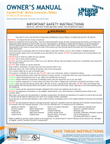
1Head Pillow
2Upper Support Arms
3FitSpine™ Table Bed
4Pivot Pins
5Hinge Plates
6 Self-Locking Hooks
73-Hole Roller Hinges w/
Traction Handles
8Handles
9Height-Selector Locking Pin
10 Boarding Platform
11 EZ Angle Tether
12 Crossbar
Located
on back of
table bed.
1
9
8
13
11
17
13 A-Frame
14 Main Shaft
15 Ankle Lock System
16 Ankle Comfort Dial™
17 Non-Skid Stability Feet
18 Storage Caddy
3
Before reading further, study the drawing below to familiarize yourself with the
important components of your Teeter Inversion Table.
A GUIDE TO YOUR INVERSION TABLE
3
6
4
57
8
17
18
2
1
3
9
14
12
11
15
16 10
13
Parts & Components
The LX9 is shown here.
Your actual model may vary.

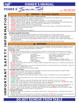
Assembled Non-Use Dimensions: 60.8 (L) x 27.5 (W) x 57.0 in (H) (154.4 x 69.9 x 144.8 cm)
Maximum In-Use Dimensions: 81.5 (L) x 27.5 (W) x 87.0 in (H) (207.0 x 69.6 x 221.0 cm)
Storage Dimensions: 27.5 (L) x 27.5 (W) x 68 in (H) (69.9 x 69.9 x 172.7 cm)
Weight (approx.): 73.6 lb (33.4 kg)
27.5 in (69.9 cm)
57.0 in (144.8 cm)
60.8 in (154.4 cm)
The LX9 is shown here.
Your actual model may vary.
Important: Please review all labels and supporting materials before using your inversion table.
This drawing indicates the locations of the warning labels found on your product. If a label is missing,
illegible or is removed, contact Teeter Customer Service to request a complimentary replacement label.
Note: Image and labels below not shown at actual size.
SAFETY WARNING LABELS
& PRODUCT SPECIFICATIONS
4
SERIOUS INJURY OR DEATH MAY OCCUR IF PRECAUTION IS NOT TAKEN. To reduce this risk:
•
READ and understand instructions in User Guide and on equipment before attempting to use.
•
ALWAYS properly set Main Shaft height. Too short can cause rapid inversion and difficultly returning upright.
• TIPPING HAZARD: To store upright, leave A-Frame open enough to remain stable or secure to wall. If children are
present, store flat on floor, not upright.
• DO NOT allow children to use this machine. Keep children, bystanders and pets away when in use.
• Keep body parts, hair, loose clothing and jewelry clear of all moving parts.
• Height / Weight Capacity: 4 ft 8 in - 6 ft 6 in (142-198 cm); 300 lb (136 kg). For consumer, indoor home-use only.
LX1053 0722-1
Replace labels and User Guide if damaged, illegible or removed.
WARNING
!
To RELEASE FROM FULL INVERSION LOCK-OUT, reach one hand behind
your head and pull the table bed toward your back. To RETURN UPRIGHT,
place arms to your sides. If this does not work, DO NOT SIT UP. Use handles
and BEND YOUR KNEES to shift body weight to the foot-side of the table bed. If
you have difficulty returning upright, consult the User Guide before next use.
AL1201 0722-1
!WARNING
Replace label if damaged, illegible or removed.

Unpack and Prepare Your Workspace
• If possible, assemble the equipment at or near the space in which you intend to use it to avoid moving it later.
• Unpack all parts and support materials. Set aside packing materials and clear your work area.
• Locate the Hardware Kits packaged with the small parts bag. They are labeled to correspond with the
assembly process.
LET’S GET STARTED
5
FIGURE 4
FOR ALL MODELS:
ASSEMBLE BOARDING PLATFORM
STEP 1
Figure 1
IMPORTANT: Do not fully tighten the bolts
until all the bolts have been screwed in and
the platform is properly aligned.
Remove the A-frame from the box and place
it on its back side so that the open ends of
the A-frame are pointing up.
Locate the Boarding Platform and the
Boarding Platform Hardware Kit, including (2)
Rubber Feet and (4) Boarding Platform Bolts.
Insert both open ends of the Boarding
Platform into the open ends of the A-frame.
INSIDE
OUTSIDE
Figure 1
Figure 2
Figure 2
NOTE: Each side of the Boarding Platform is
secured to the A-frame through two holes,
‘inside’ and ‘outside’. The ‘inside’ holes are
also used to secure the Boarding Platform
Rubber Feet.
Facing the underside of the Boarding Platform,
position a Rubber Foot over one inside hole
and hand-tighten with a Boarding Platform
Bolt. Repeat on the other side.
Hand-tighten a Boarding Platform Bolt into
one outside hole. Repeat on the other side.

Figure 3: Fully tighten all Boarding Platform
Bolts using the 5mm Allen Wrench.
6
Figure 4: Position the assembled A-frame
upright and open it on a level surface,
ensuring the Boarding Platform and
Rubber Feet are secure and rest evenly
on the ground.
Figure 3
Figure 4

Figure 5
NOTE: The Storage Caddy is included with LX9
Models and must be attached BEFORE the Handles.
If your inversion table does not include a Storage
Caddy, proceed to the next step.
Locate the Storage Caddy with the included Phillips
Head Screwdriver and (1) Screw.
Locate the Left Handle. Markings on the Handles
differentiate the Left and Right Handles.
Align the Storage Caddy under the Hinge Cover of the
Left Handle, so that it fits over the bottom Bolt hole.
Screw in (1) Screw with the Phillips Head Screwdriver
provided until securely fastened.
7
FOR LX9 MODELS:
ASSEMBLE STORAGE CADDY
Figure 5
Figure 6
Figure 6: Ensure the Storage Caddy is securely
attached to the handle.

Figure 7-9
IMPORTANT: Do not fully tighten the bolts until
all the bolts have been screwed into the Handles
AND the Handle Brackets.
Locate the Right and Left Handles and the
Handle Hardware Kit including (6) Handle Bolts.
Noting Left and Right markings, align the Right
Handle with the Right side of the A-frame and
hand tighten (3) Handle Bolts.
Repeat these steps on the Left side of the
A-frame to assemble the Left Handle.
FIGURE 4FIGURE 4
STEP 2 ASSEMBLE HANDLES & BRACKETS
8
Figure 10: Align (2) Handle Bracket Bolts through
the Bolt holes in the Handle Bracket Set and
loosely secure the (2) Handle Bracket Screws into
the Bolts using (2) 5mm Allen Wrenches.
Repeat these steps on the Right side to assemble
the Right Handle Bracket Set.
Fully tighten all the Handle Bolts with the 5mm
Allen wrench.
Figure 11: Fully tighten all the Handle Bracket
Bolts and Screws using (2) 5mm Allen wrenches.
Figure 10 Figure 11
Figure 9 - 9a: Locate the Handle Bracket Set,
(4) Handle Bracket Bolts and (4) Handle Bracket
Screws included in the Handle Assembly
Hardware Kit.
Noting Left In/Out and Right In/Out markings,
sandwich the Left Handle Bracket Set over the
area where the Left Handle meets the A-frame
by clamping both sides of the Handle Bracket
Set together.
Figure 9
Figure 9a
Figure 8
Figure 7

UNLOCKED LOCKED
FIGURE 4FIGURE 4
STEP 3 ASSEMBLE ROLLER HINGES
TO TABLE BED
Figure 12
NEVER disassemble the Roller Hinge Pivot Pin.
ALWAYS insert the 3-Hole Roller Hinge (with the Pivot Pin on top
and facing out) in the same direction as the arrow label located
inside of the Cam Lock for proper assembly.
WARNING
!
Figure 12: Familiarize yourself with the 3-Hole Roller
Hinge and Cam Lock terms.
Figure 13
Your Roller Hinge setting and balance may vary depending on your
bodyweight distribution. Refer to User Guide for troubleshooting.
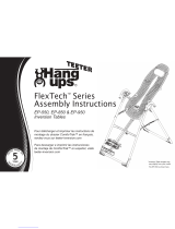
Do not use Setting A for
users over 220 lb (100 kg).
WARNING
!
ABC
Preferred Maximum
Inversion Angle
Your
Body Weight
80-120 lb
(36-54 kg)
120-220 lb
(54-100 kg)
220-300 lb
(100-136 kg)
Partial Inversion
(0-60°)
Full Inversion
(0-90°)
A
A
B
B
C
C
Recommended
Hole Selection
More
Responsive Less
Responsive
Figure 13: The Roller Hinges control the
responsiveness or rate of rotation of the inversion
table. There are three holes; the hole selection
depends both on your body weight and your
preferred angle of inversion. The “A” setting is the
top hole closest to the pivot pin, “B” is the middle
hole, and “C” is the bottom hole. Determine your
recommended hole selection using the chart below.
Bracket Pin Cam Lock
Pivot Pin Bracket
Full (0-90°): A more responsive
setting that will allow users to
rotate to any angle and lock out in
full inversion.
Recommended for beginners
Partial (0-60°): A less responsive
setting for users who prefer partial
inversion without the option of
full inversion.
9

10
Figure 14a
Figure 14
Figure 15
Figure 16
Figure 14: For ease of assembly, rest the Table Bed
against the Crossbar at the front of the A-frame.
Figure 14a: On one side of the Table Bed, lift and
hold the Cam Lock up all the way to unlock.
In your other hand, hold one Roller Hinge near the
Pivot Pin. With the Pivot Pin facing out (away from
the Table Bed), slide the bottom of the Roller Hinge
between the Cam Lock and the Bracket in the
same direction as the arrow label located inside of
the Cam Lock.
TIP: Make sure that the Cam Lock is completely
open when inserting the Roller Hinge, otherwise
assembly will be more difficult.
Figure 15: Engage one of the holes in the Roller
Hinge over the Bracket Pin. Push down on the
Cam Lock to lock it and secure the Roller Hinge.
Repeat on other side. Make sure the Roller Hinges
are in the same hole setting on both sides.
Figure 16: This figure shows the Roller Hinge
installed correctly, with the Bracket Pin engaged in
Setting C. Use your recommended hole selection
based on the chart from page 9.
CLOSED / LOCKED

FIGURE 4FIGURE 4
STEP 4 ASSEMBLE TABLE BED TO A-FRAME
Failure of the Self-Locking Hooks to close over both Roller Hinge
Pivot Pins is an indication of improper assembly and if not cor-
rected could result in serious injury or death!
WARNING
!
Figure 20: Rotate the Table Bed so that it is facing
up. Ensure that it rotates smoothly. See also Image
A on Page 13 to ensure misassembly has not
occurred.
TOP VIEW
INSIDE VIEW
Figure 18: Lower each Roller Hinge Pivot Pin into the
A-frame hinge plates, one side at a time. The Self-
Locking Hooks will open to allow the Pivot Pin into
the Hinge Plate slot, then automatically snap closed
over the Pivot Pin.
TIP: You may need to push outward on the Hinge
Plate in order for the second Pivot Pin to lock in
place.
Figure 19a & 19b: Make sure that each Pivot Pin is
seated at the base of the slot in the Hinge Plates, and
that the Self-Locking Hooks have closed over both
Pivot Pins.
Figure 17: Face the front of the A-frame where the
Crossbar is located. Grasp both Roller Hinges, right
above the Cam Lock, and lift the Table Bed. Allow
the top of the Table Bed to rotate toward the floor, so
that the back of the Table Bed is now facing you and
the top of the Table Bed is in front of the Crossbar.
Figure 17
Figure 18
Figure 20
Figure 19b
Figure 19a
The LX4 is shown here. Your actual model may vary.
11

FIGURE 4FIGURE 4
STEP 5 ASSEMBLE MAIN SHAFT TO TABLE BED
Figure 21
Figure 22
REVISIONS
ENGR
DATE
REV
SHT
ZONE
DESCRIPTION
NMS
10/18/2017
A
1
8D
A1: RELEASE FOR PATENT
PARTS LIST
ITEM
QTY
NET DIMENSIONS/DESCRIPTION
NOTE
MATERIAL
SHT
REVISION STATUS
SHT
1
REV
A
8
A
1234567
D
C
B
C
A
D
B
5 3 16 248 7
8
A
1234567
D
C
B
C
A
D
B
5 3 16 248 7
figure 18
SHEET 1 OF 1
REV
PROJECT:
DRAWN
UNLESS OTHERWISE NOTED
SURFACE ROUGHNESS PER ANSI B46.1
DIMENSIONING PER ASME Y14.5-2009
WELD SYMBOLS PER AWS A2.4
FINISH:
UOS 63RMS ON
MACHINED
SURFACES OR
AS PROCURED
.X
.XX
.XXX
ANGLE
EXPECTATIONS PROPRIETARY
THE INFORMATION CONTAINED HEREIN
IS PROPRIETARY TO EXPECTATIONS AND
SHALL NOT BE REPRODUCED IN WHOLE
OR IN PART OR USED FOR ANY PURPOSE
EXCEPT WHEN SUCH USER POSSESSES
DIRECT WRITTEN AUTHORIZATION
FROM EXPECTATIONS LLC
SCALE: FULL
SIZE:
D
A
TOLERANCES
UNLESS NOTED
=
.1
=
.03
=
.005
=
1
NICK SOLLER
FILLET RADII: .005-.010
CORNER BREAK: .005-.010
ALL DIMENSIONS IN INCHES
EXPECTATIONS LLC
PUYALLUP, WA 98391
DRAWING
PROJECT NAME HERE
Figure 21a
Figure 23
The LX9 is shown here. Your actual model may vary.
12
Figure 23: Test the inversion table by hand
for smooth and steady rotation and ensure
that all fasteners are secure.
Figure 21: Stand on the LEFT side of the
A-frame, holding the Main Shaft with the
height markings facing up. Begin to slide
the end of the Main Shaft into the Main Shaft
Housing at the base of the Table Bed.
Figure 21a: With your right hand, pull out the
Height-Selector Locking Pin and slide the
Main Shaft in further. Release in the desired
height setting. Refer to the User Guide for
more information on selecting your height
setting.
Figure 22: The Main Shaft MUST REST against
the Crossbar of the A-frame.
IMPORTANT: The Crossbar prevents the Table
Bed from rotating forward when the user
steps on the Ankle Comfort Dial. If the Main
Shaft does not rest on the Crossbar as shown
here, then the Table Bed has been assembled
backwards onto the A-frame. This must be
corrected before use.

Image B
Go back to Step 4
for instruction.
Demonstrates that the Table
Bed has been assembled
into the A-Frame backwards
so the Main Shaft is not
resting on the Crossbar and
must be corrected.
Image A
Go back to Step 3
for instruction.
Demonstrates that the
Roller Hinges have been
assembled upside down
into the Table Bed and
must be corrected.
If your Teeter Inversion Table looks like Image A or B, your inversion table has
been misassembled and is unfit for use. Improper assembly could result in serious injury or death!
WARNING
!
MISASSEMBLY CHECK
13
Image C
Proceed to
Step 6.
Shows correct assembly.

Attach Head Pillow
Figure 25: Locate the slots at the top of the Table
Bed just beneath the Handhold as shown.
Insert the two pointed ends on the back of the
Head Pillow into the slot of the Table Bed and pull
through from the back of the Table Bed to secure
the pillow into position.
REVISIONS
ENGR
DATE
REV
SHT
ZONE
DESCRIPTION
NMS
10/18/2017
A
1
8D
A1: RELEASE FOR PATENT
PARTS LIST
ITEM
QTY
NET DIMENSIONS/DESCRIPTION
NOTE
MATERIAL
SHT
REVISION STATUS
SHT
1
REV
A
8
A
1234567
D
C
B
C
A
D
B
5 3 16 248 7
8
A
1234567
D
C
B
C
A
D
B
5 3 16 248 7
figure 22
SHEET 1 OF 1
REV
PROJECT:
DRAWN
UNLESS OTHERWISE NOTED
SURFACE ROUGHNESS PER ANSI B46.1
DIMENSIONING PER ASME Y14.5-2009
WELD SYMBOLS PER AWS A2.4
FINISH:
UOS 63RMS ON
MACHINED
SURFACES OR
AS PROCURED
.X
.XX
.XXX
ANGLE
EXPECTATIONS PROPRIETARY
THE INFORMATION CONTAINED HEREIN
IS PROPRIETARY TO EXPECTATIONS AND
SHALL NOT BE REPRODUCED IN WHOLE
OR IN PART OR USED FOR ANY PURPOSE
EXCEPT WHEN SUCH USER POSSESSES
DIRECT WRITTEN AUTHORIZATION
FROM EXPECTATIONS LLC
SCALE: FULL
SIZE:
D
A
TOLERANCES
UNLESS NOTED
=
.1
=
.03
=
.005
=
1
NICK SOLLER
FILLET RADII: .005-.010
CORNER BREAK: .005-.010
ALL DIMENSIONS IN INCHES
EXPECTATIONS LLC
PUYALLUP, WA 98391
DRAWING
PROJECT NAME HERE
Figure 25
Attach Angle Tether
The tether will come pre-assembled to the A-frame.
Figure 24: Unfold the adjustable tether and clip it to
the U-Bar on the underside of the Table Bed.
Slide the buckle to lengthen or shorten the strap
depending on your desired maximum angle of
inversion.
Figure 24 LENGTHEN
SHORTEN
FIGURE 4
STEP 6 ATTACH ANGLE TETHER
& HEAD PILLOW
14

FIGURE 4 ATTACH LUMBAR BRIDGE (OPTIONAL)
STEP 7
Stabilize the inversion table to prevent rotation
during assembly.
Position the Lumbar Bridge with the Teeter logo at the
base and facing towards you.
Figure 26: Insert the bottom two notches of the bridge
into the desired horizontal slots on the lower portion of
the Table Bed.
Use of the Lumbar Bridge may impact the rotation of
the table. Set the Angle Tether to a moderate inversion
angle and use a spotter until you are able to find the
correct balance settings and are comfortable with the
operation of the table.
Start in a lower level arch setting and work your way up.
If you feel any discomfort, lower the setting until you are
comfortable or discontinue use.
Figure 28: The Lumbar Bridge works between
intermediate to moderate inversion. Full inversion
moves the body away from the table bed and will
reduce the effectiveness of the bridge.
Figure 27: Bend the bridge to the arch height you desire
and insert the one top notch into the corresponding slot
on the upper portion of the Table Bed.
Modify the positioning and arch height as needed.
NOTE: Long-term storage of the Lumbar Bridge in a
high arch setting may result in distortion of the shape
and ability of the bridge to move to lower arch settings.
Store in its flat position when not in use.
Use Instructions
Figure 26
Figure 27
Figure 28
The Lumbar Bridge provides even deeper decompression and improved alignment benefits.
Personalize the intensity and target zone of the Lumbar Bridge by adjusting the height and
position of the arch within the slots on the Table Bed so it fits comfortably at the small of
your back.
15

FIGURE 4 ATTACH ACUPRESSURE NODES (OPTIONAL)
STEP 8
Start with the smaller nodes and work your way up
to the larger ones. The ideal placement of the nodes
depends on where your muscle tension points align
with the slots in the table bed.
The pressure of the nodes will vary as the table
rotates up or down. The nodes work best between
intermediate to moderate inversion (20-45 degrees).
Full inversion moves the body away from the table
bed and will reduce the effectiveness of the nodes.
While inverted, stay at a static incline to maintain a
steady pressure, or oscillate (move between different
angles of inversion) for a massaging action.
Use of the nodes may cause muscle soreness. If you
feel any discomfort, decrease or discontinue use.
Figure 29: Determine your desired Acupressure
Node position along the table bed. Unscrew the black
backing from the node and insert the backing into the
slot from the rear of the bed so the threads are visible
from the front.
Figure 30: Twist the node clockwise into the backing
to secure. Do not overtighten to avoid damaging
the node.
Repeat, as desired, with additional nodes.
To shift node placement within a track, simply loosen
the backing and slide the node in the slot.
Use Instructions
Figure 29
Figure 30
Personalize the intensity and target zone of the Acupressure Nodes by positioning the varying
sizes along the FitSpine bed tracks as desired.
Figure 31
16

Figure 32
Figure 32a
Ensure User Guide Remains on Product
Figure 32 & 32a: If the User Guide is not already
attached, secure the chain to the A-frame through the
designated hole in the Hinge Plate. Allow the User Guide
to hang freely on the outside of the A-frame Spreader
Arms so it doesn’t interfere with the rotation of the Table
Bed.
IMPORTANT: Once attached to the A-frame, DO NOT
remove the User Guide. It should remain permanently
attached to your inversion table to serve as a reference
for all users in regard to proper adjustment and use of
the equipment.
WARNING
!
Read the User Guide thoroughly before using your
Teeter Inversion Table. Improper settings could result
in serious injury or death!
The LX4 is shown here. Your actual model may vary.
Locate User Guide and
Get Started with Inversion
NEXT STEP
Refer to the User Guide attached to your FitSpine LX Inversion Table.
This is your step-by-step guide to customizing your user settings for a
smooth and effortless inversion experience.
17

18
HOW TO SUBMIT YOUR REGISTRATION:
Step 1
Fill out this information for your own records.
Step 2
Go online to teeter.com to register your warranty.
Handling and transportation costs related to product warranty service only are covered by this warranty. This
warranty does not cover damage resulting from improper handling, assembly, or installation, repairs made by
others, accident, misuse, or abuse. Under no circumstances shall Teeter, or any other party involved in the sale
of this product, have any liability for incidental or consequential damage arising from breach of an express or
implied warranty on any Teeter product.
EXCEPT AS SET FORTH ABOVE, NO WARRANTY IS GIVEN WITH RESPECT TO ANY TEETER PRODUCT, AND
ALL EXPRESS WARRANTIES ARE DISCLAIMED. This warranty shall be governed by the laws of the State of
Washington, USA. To the extent this warranty is found not to be enforceable, it shall be deemed revised to
the extent necessary to make it enforceable. This warranty and any controversy or claim arising out of this
warranty or its interpretation shall be governed by the laws of the State of Washington, USA. Any controversy
or claim arising out of or relating to this warranty, its interpretation, or any alleged breach thereof, which
cannot be amicably settled between Teeter and the owner within sixty (60) days of written notice by the
aggrieved party to the other, shall be finally settled by arbitration submitted to three (3) arbitrators selected
from the panels of the arbitrators of the American Arbitration Association located closest to Teeter’s principal
place of business.
Some states do not allow the exclusion of incidental or consequential damage from a warranty, so the above
limitation or exclusion may not apply to you. Some states do not allow limitations on how long an implied
warranty lasts, so the above limitation may not apply to you. This warranty gives you specific legal rights, and
you may also have other rights which may vary from state to state.
Date of Purchase
Product & Model
Dealer Name
Serial No. (located on the back of the Table Bed)
During the period starting with the day of retail purchase and continuing for five
(5) years, Teeter extends to the owner a repair and replacement warranty against
manufacturing defects in materials, workmanship, fabrics and padding. Teeter
will repair or replace any such defect and will pay the costs of all parts, labor and
transportation. If a repair or replacement is not commercially practical or cannot timely
be made, then Teeter will, at the original Purchaser’s option, replace with a comparable
product or refund the purchase price.
FULL 5 YEAR WARRANTY
The Teeter warranty set forth below and on Teeter’s website applies to US and Canadian customers
only. For international customers, please consult your local distributor for warranty information which
will vary depending on country.
If you are unable to go online, you can request a warranty card to be mailed to you by calling Customer Service at 800-847-0143.
Please DO NOT mail this to Teeter.
1O-YEAR PREMIUM EXTENDED WARRANTY AVAILABLE
Purchase an additional 5 years of repair and replacement warranty against manufacturing defects in materials
and workmanship. Visit teeter.com to purchase and view full terms and conditions.
/