Page is loading ...

Not for
Reproduction
42” Single-Stage Snowthrower
Model No. Description
1696423-00 42” Single Stage Snowthrower
1756467
Rev: B
ATTACHMENT
OPERATOR’S
MANUAL
Copyright © 2014 Briggs & Stratton Power Products Group, LLC
Milwaukee, WI USA. All Rights Reserved.

Not for
Reproduction
2

Not for
Reproduction
3
Table of Contents
Hardware ........................................................................................ 4
Hardware Contents ................................................................... 4
Operator Safety ............................................................................. 6
Operator Safety ......................................................................... 6
General ..................................................................................... 6
Preparation ................................................................................ 6
Operation .................................................................................. 6
Recommended Accessories ..................................................... 7
Decals ....................................................................................... 7
Features & Controls ...................................................................... 8
Control Functions ...................................................................... 8
Tractor Controls ......................................................................... 8
Assembly ....................................................................................... 9
Unpacking ................................................................................. 9
Chute Assembly ........................................................................ 9
Install Hitch Assembly ............................................................... 10
Attach Snowthrower to Tractor ................................................... 12
Attach Lift Arm Assembly to Tractor ........................................... 12
Attach Chute Motor Wiring Harness (Non-electric Deck Lift Models) ....... 14
Attach Chute Motor Wiring Harness (Electric Deck Lift Models) ............ 15
Install Reectors ........................................................................ 16
Operation ....................................................................................... 17
Checks Before Starting ............................................................. 17
Engine & Ground Speed Selection ............................................ 17
Transporting ............................................................................. 17
Snow Removal Suggestions ...................................................... 18
Storage ........................................................................................... 18
Daily Storage ............................................................................. 18
O-Season Storage................................................................... 18
Troubleshooting, Adjustments & Service .................................. 19
Troubleshooting Chart ............................................................... 19
Skid Shoe Adjustment ............................................................... 20
Electric Chute Rotator Gear ...................................................... 20
Lift Adjustment .......................................................................... 20
Belt Tension Adjustment ............................................................ 20
Maintenance .................................................................................. 21
Schedule for Normal Care ......................................................... 21
General Lubrication ................................................................... 21
Warranty ......................................................................................... 22
NOTE: In these instructions, “left” and “right” are referenced from the
operating position.
Table of Contents
Not for
Reproduction
4
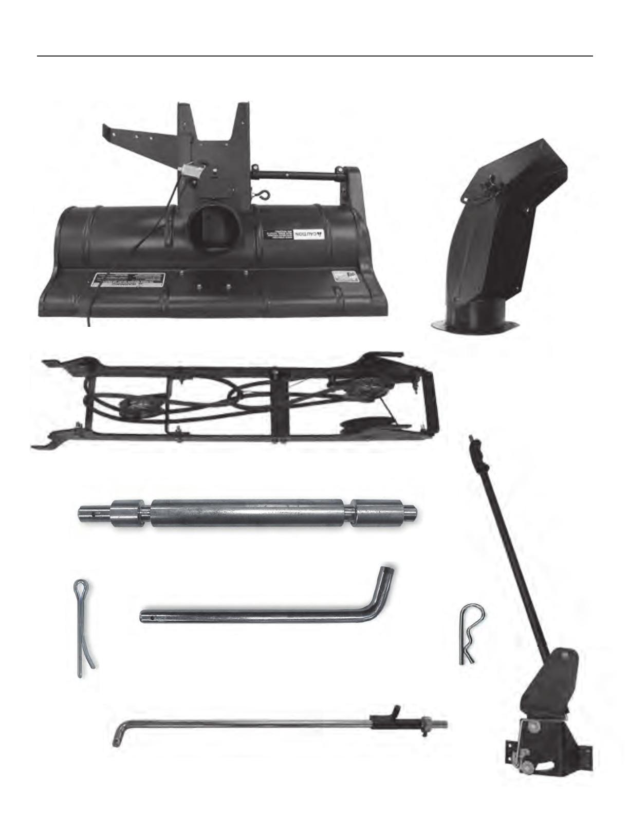
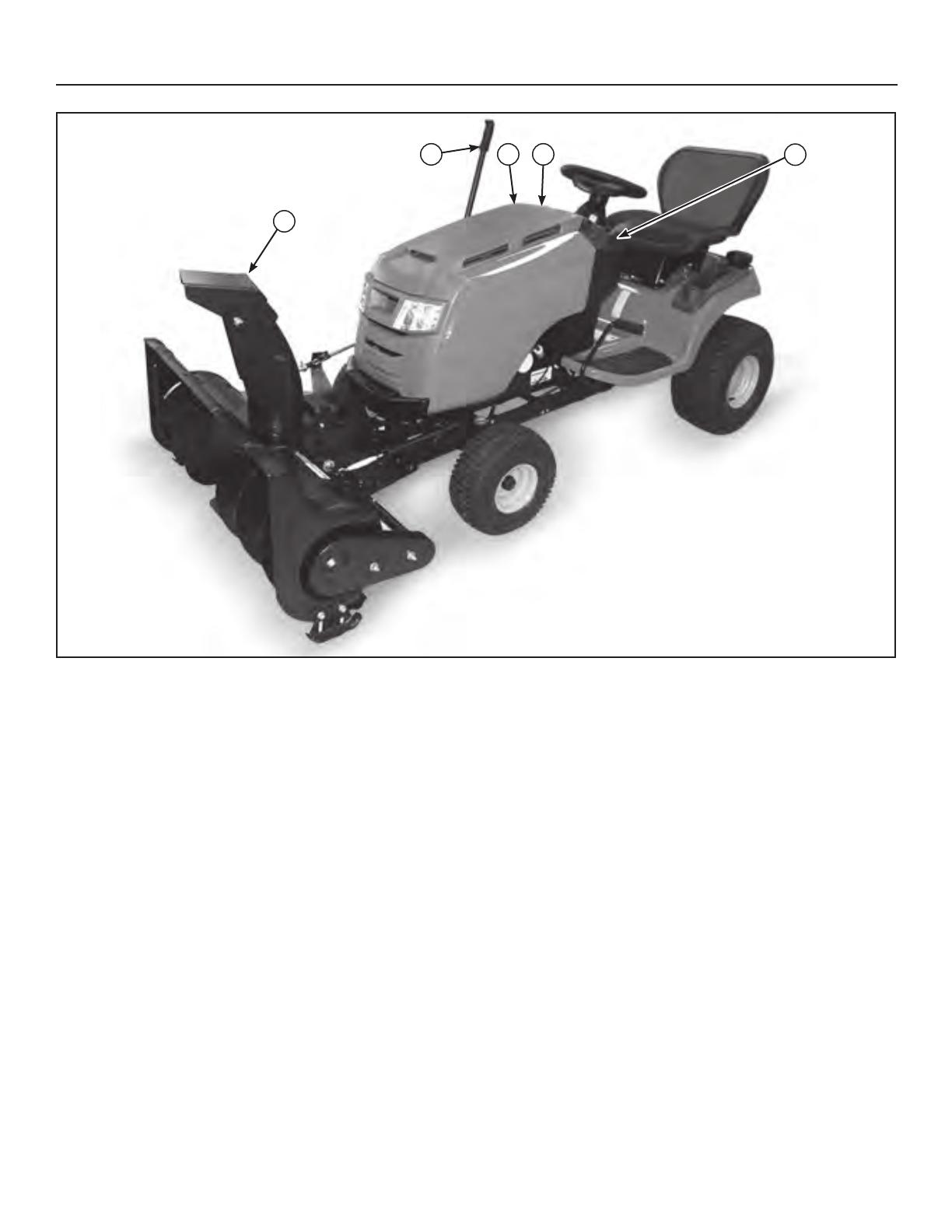
Hardware Contents
F - HITCH LATCH PIN
H - LIFT ARM ASSEMBLY
(Not in Hardware Bag /Box)
B - CHUTE
(Not in Hardware Bag /Box)
A - SNOWTHROWER
(Not in Hardware Bag /Box)
D - HITCH SUPPORT SHAFT
C - HITCH ASSEMBLY
(Not in Hardware Bag /Box)
E - COTTER PIN
G - HAIR PIN
I - LIFT ROD ASSEMBLY
Not for
Reproduction
5
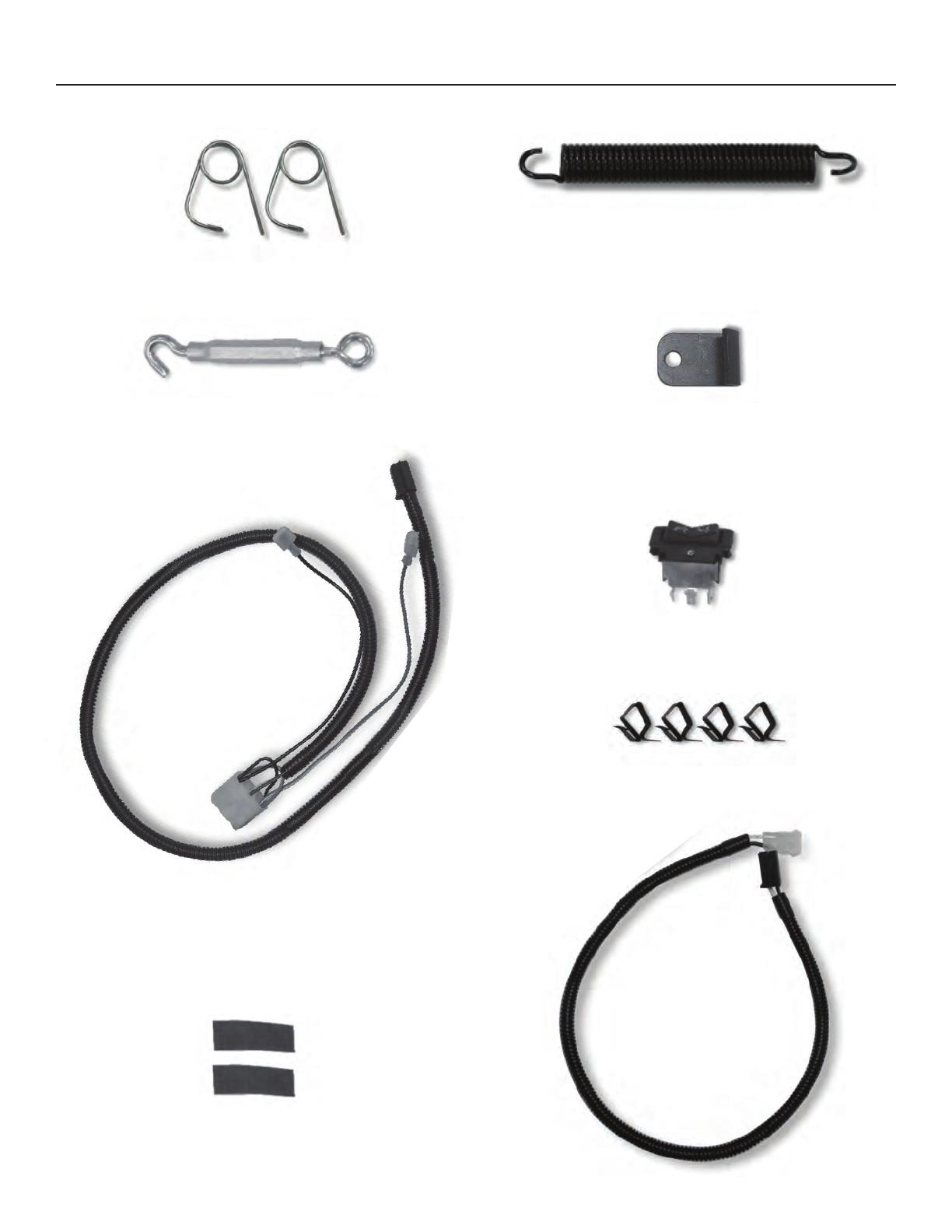
N - UPPER WIRE HARNESS
Hardware Contents
R - EXTENSION
WIRE HARNESS - 26”
K - SPRINGJ - SAFETY CLIP (Qty. 2)
L - TURNBUCKLE M - AXLE CLAMP
O - SWITCH
P - CLIPS (Qty. 4)
Q - REFLECTORS (Qty. 2)
Not for
Reproduction
6
Operator Safety
This snowthrower is capable of amputating hands and feet and throwing objects. Failure to observe the following
safety instructions could result in serious injury. Read these safety rules, and the safety rules in your tractor
Operator’s Manual, and follow them closely. Failure to obey these rules could result in loss of control of vehicle,
severe personal injury to yourself, or damage to property or equipment. The triangle in the text signifies
important cautions or warnings which must be followed.
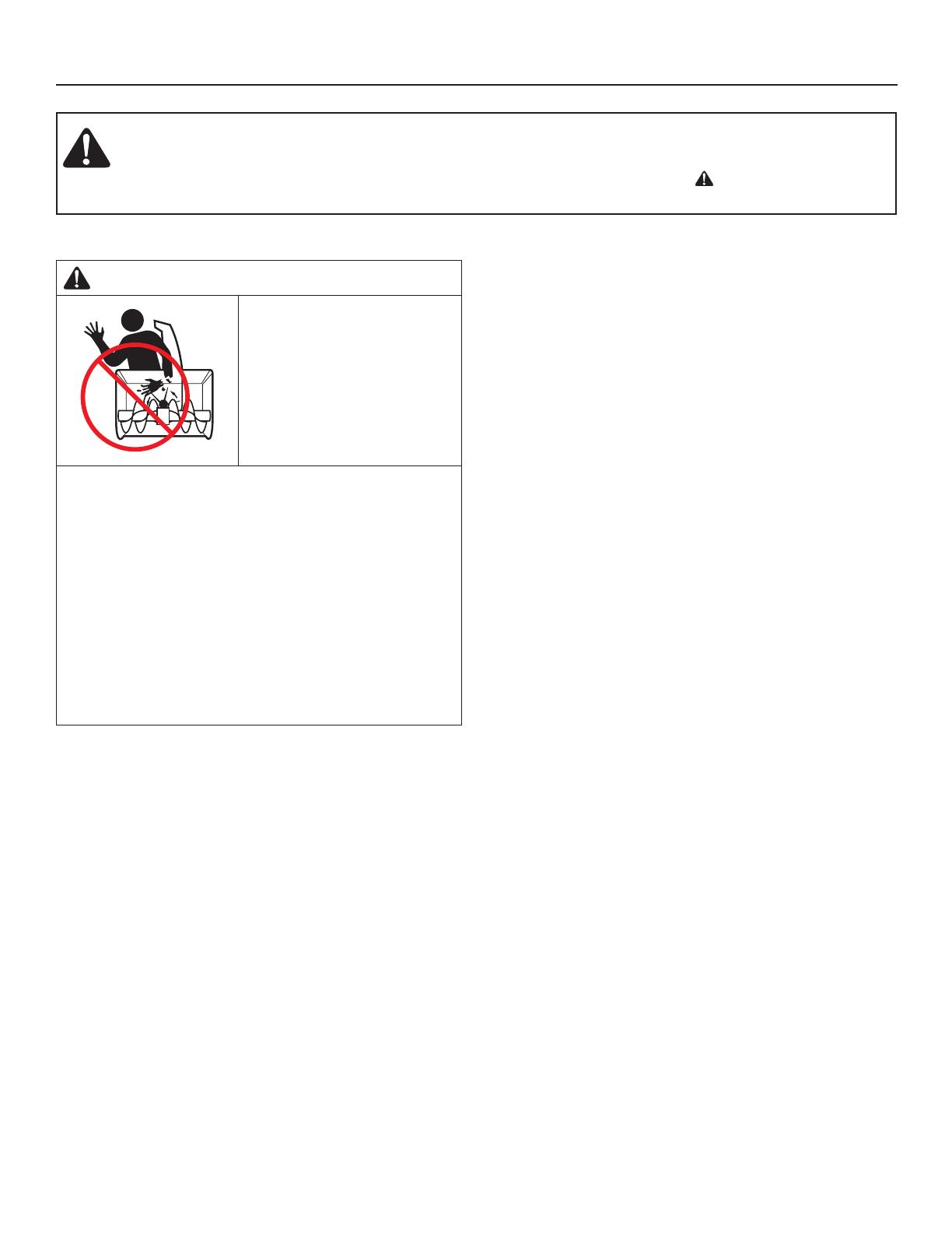
Operator Safety
DANGER
Amputation hazard
The discharge chute
contains a rotating impeller
to throw snow. Fingers can
quickly become caught in
the impeller. Never clear or
unclog the discharge chute
with your hands. Always
use a clean-out tool.
Failure to observe these safety instructions will
result in traumatic amputation or severe laceration.
Hand contact with the rotating impeller inside the
discharge chute is the most common cause of injury
associated with snowthrowers. Never use your hands to
clean out the discharge chute.
To safely clear a clogged discharge chute, follow
these instructions:
1. Shut OFF the engine.
2. Wait 10 seconds to be sure the impeller blades have
stopped rotating.
3. Always use a clean-out tool, not your hands.
General
• Read this manual and the tractor Operator’s Manual
carefully. Be thoroughly familiar with the controls and
the proper use of the equipment.
• If snowthrower is equipped with a spring-assist tension
lever, never pull the spring-assist tension lever back
unless snowthrower is in fully raised position. The
spring is under tension when snowthrower is in lowered
position.
• Never allow children to operate the machine. Do not
allow adults to operate it without proper instruction.
• Do not carry passengers.
• Keep the area of operation clear of all persons,
particularly small children, and pets.
• Never direct discharge chute towards bystanders.
• Make sure all hardware is secure and that snowthrower
is in good operating condition.
• Check to be sure all safety devices and shields are in
place.
• Check that all adjustments are correct before using this
unit.
Preparation
• Never attempt to make any adjustments while engine is
running.
• Thoroughly inspect the area where the snowthrower is
to be operated and remove all foreign objects.
• Adjust the skid shoe height to clear gravel or crushed
stone surface. See the Maintenance and Adjustments
section for procedure.
• One wheel weight on each rear wheel or rear weights is
required.
Operation
• Exercise extreme caution when operating on, or
crossing, gravel drives, walks or roads. Stay alert for
hidden hazards or traffic.
• Never allow anyone in front of the machine while it is
operating.
• After striking an object or if unit starts to vibrate
abnormally, stop the engine, disengage the PTO, and
remove the key. Check for the cause and any damage
before restarting. Before any inspection, make sure all
moving parts have stopped.
• Take all possible precautions before leaving operator’s
position. Disengage the PTO, lower the attachment, set
the parking brake, stop the engine and remove the key.
• Never operate the snowthrower near glass enclosures,
automobiles, window wells, dropoffs, etc., without
proper adjustment of discharge angle.
• Do not overload machine capacity by attempting to
clear snow at too fast a rate.
• Never operate unit at high transport speeds on slippery
surfaces. Use care when travelling in reverse.
• Disengage power to snowthrower when transporting or
not in use.
• Never operate the snowthrower without good visibility or
light.
• Always be sure your feet are properly placed on the
footrests and keep a firm hold on the steering wheel.
Not for
Reproduction
7
Operator Safety
WARNING
Perform the Safety System Interlock test found in your
tractor Operator’s Manual. If tractor does not pass the
test, do not operate the tractor. See your authorized
dealer. Under no circumstances should you attempt to
defeat the safety system.
Operating on Slopes
WARNING
• Never operate on slopes greater than 10°.
• Select slow ground speed before driving onto a
slope. Avoid using brakes to control speed.
• Drive up and down the face of the slopes, never
across the slope face.
• Use caution when changing directions and DO NOT
START OR STOP ON A SLOPE.
Recommended Accessories
Tire chains are recommended when installing this
attachment to your unit.
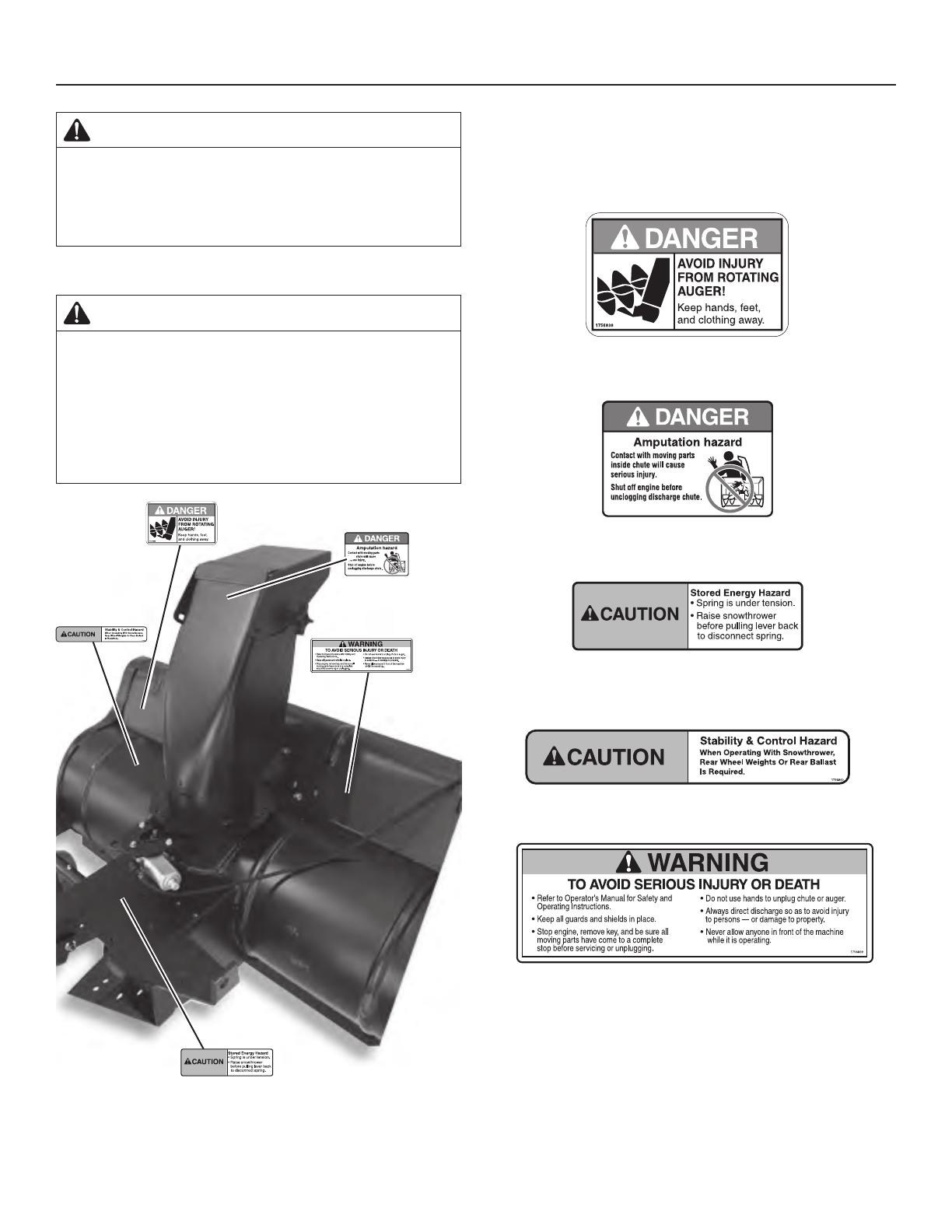
Safety Decals
Part No. 1756838
Danger Decal - Auger
Part No. 1756841
Danger Decal - Discharge Chute
1756841
Part No. 1756842
Caution Decal - Spring Tension
(If equipped with spring-assist tension lever.)
1756842
Part No. 1756840
Caution Decal - Stability & Control
Part No. 1756839
Warning Decal - Avoid Injury
1756841
1756842
Not for
Reproduction
8
Features and Controls
Tractor Controls
Before you begin operating the tractor and attachment,
make certain you have:
• Read and understood the instructions in the tractor
Operator’s Manual.
• Become thoroughly familiar with all of the tractor
controls and their operation, including how to safely and
properly start and stop the unit.
• Practice driving in an open area, without the attachment,
to become accustomed to the unit.
A. Electric Chute Rotator Switch – On tractor models
with electric height of cut switch.The electric height
of cut switch will become the spout rotator switch.
B. PTO Switch – Engages and disengages the PTO to
start and stop the snowthrower.
C. Manual Attachment Lift Lever – The attachment lift lever
raises and lowers the attachment. To RAISE an attachment,
depress the release button on top of the lever and pull back.
To LOWER an attachment, depress the release button and
move the lever forward. When lowering the attachment, be
sure to push the lever fully forward into the locked position
D. Deflector Lock Knob – The snowthrower discharge
deflector angle can be changed by loosening the lock knob,
changing the deflector angle and tightening the lock knob.
E. Throttle Control – Always operate at FULL throttle.
Control Functions
The information below briefly describes the function of
individual controls. Operating the tractor and attachment
requires the combined use of these controls and additional
controls whose operation is described in the tractor
Operator’s Manual.
Please take a moment and familiarize yourself with the
name, location, and function of these controls so that you
will better understand the safety and operating instructions
provided in this manual.
A BC
D
E
Not for
Reproduction
9
Hardware / Parts Identication
Lower case letters identify pre-assembled and / or pre-
existing hardware / parts.
Upper case letters identify hardware / parts that are found in
the kit (pages 4-5).
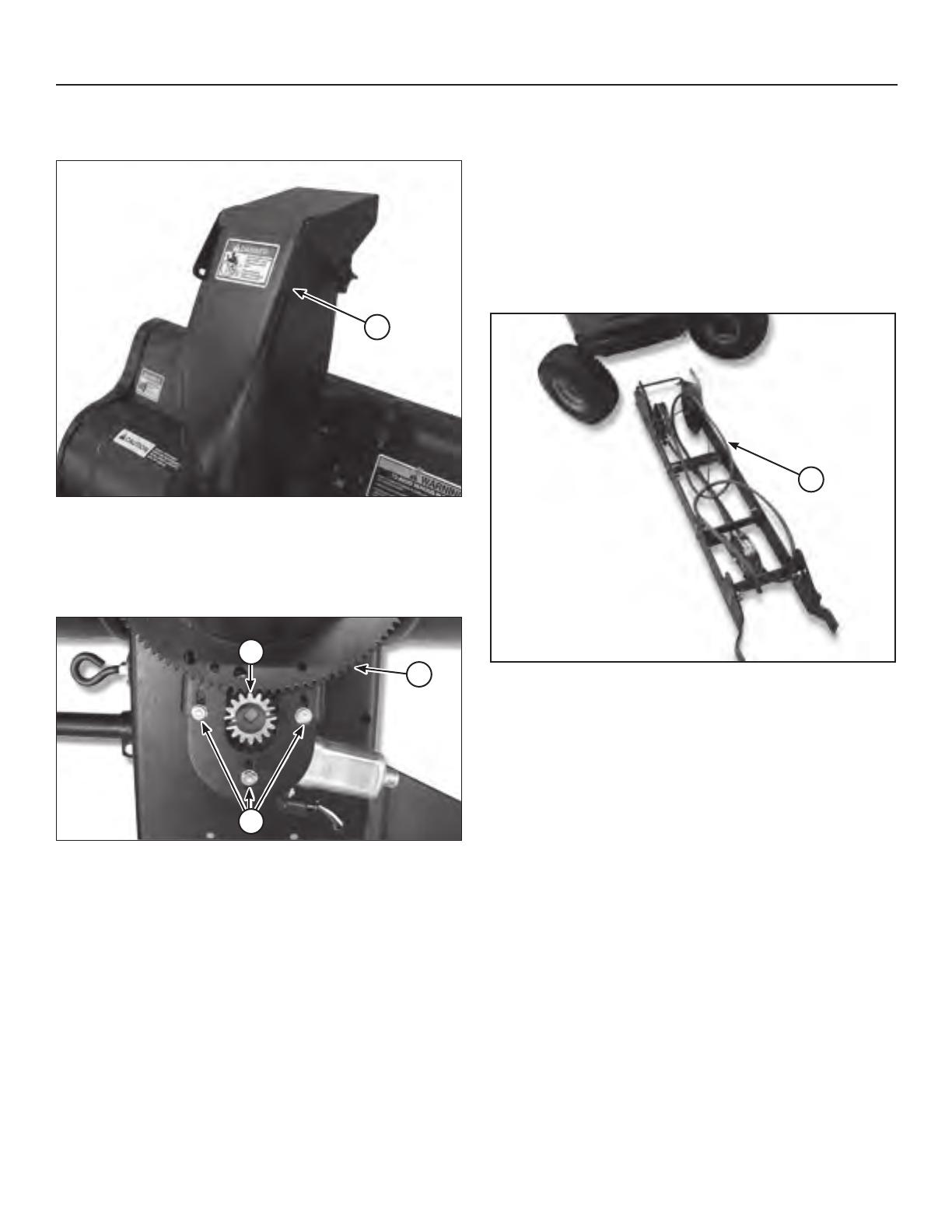
Unpacking
1. Position box close to the tractor and carefully unpack
and organize snowthrower parts.
IMPORTANT: See (a, Figure 1) for correct orientation of
snow drive pulley hub.
2. If snow drive pulley hub orientation is incorrect, loosen
set screw, remove and flip pulley to correct orientation
and tighten set-screw.
CORRECT
INCORRECT
a
Figure 1
Assembly
Chute Assembly
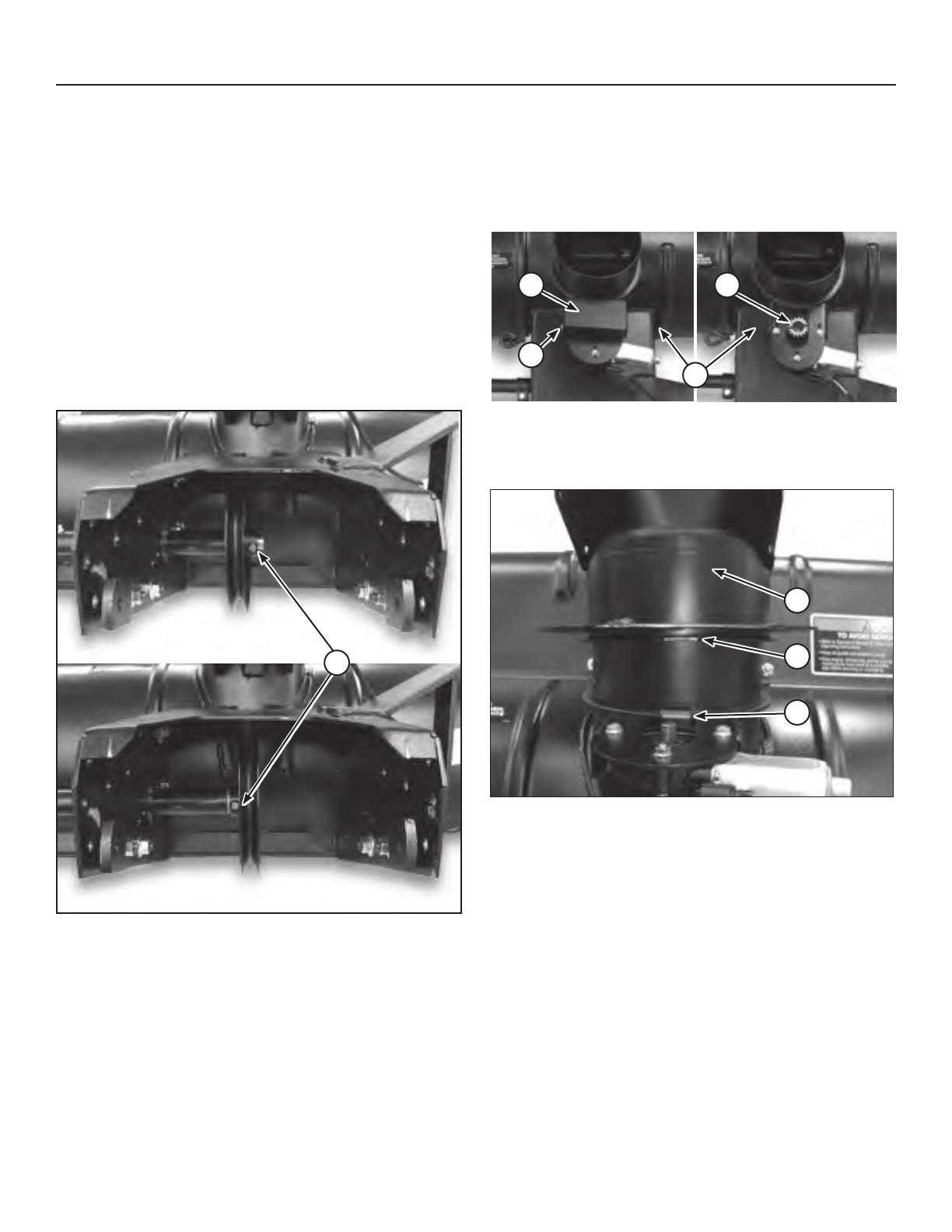
1. Remove gear cover (a, Figure 2) from the snowthrower
assembly (A) by removing hex screw (b) and tilting the
gear cover to disengage tab on opposite side of box.
2. Remove chute rotator gear (c) from shaft.
a c
b
a
A
Figure 2
3. Align chute (B, Figure 3) notch (d) on chute with
housing chute ring tab (e) and slide chute into place.
B
d
e
Figure 3
Not for
Reproduction
10
Assembly
4. Rotate chute 180 degrees to front. Chute (B, Figure 4)
opening should be facing front / center of machine.
B
Figure 4
5. Loosen the three nuts (f, Figure 5) on motor assembly.
Replace chute rotator gear(g) onto shaft and mesh the
teeth with chute ring gear (h). Slide motor assembly
forward and tighten the nuts.
f
g
h
Figure 5
6. Replace gear cover over rotator gear mechanism and
secure with the hex bolt (Refer to left side Figure 2.).
NOTE: Engage cover tab on gear box opposite of hex
bolt.
Install Hitch Assembly
1. Remove the mower deck. Refer to Tractor Operator
Manual.
2. Turn the front wheels fully to the left.
3. Place hitch (C, Figure 6) on floor in front of tractor as
shown.
NOTE: If this is a new installation, cut the plastic ties
holding the snow thrower drive belt for shipping, but do
not remove the belt.
C
Figure 6
Not for
Reproduction
11
Assembly
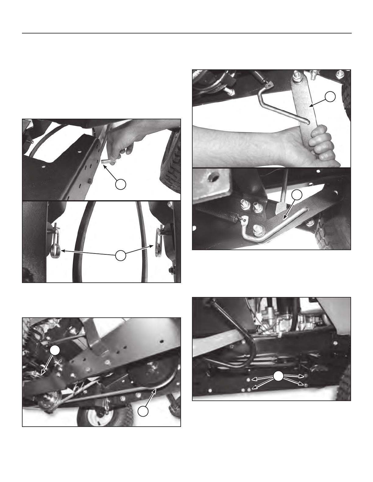
4. On underside of tractor frame, locate 11/16” holes
approximately 14” forward from rear tire. Insert hitch
support shaft (D, Figure 7). Secure with the cotter pin
(E) on inside of frame and slightly bend longest leg up.
IMPORTANT: The cotter pin must be located along the
inside edge of the tractor frame.
5. Slide hitch assembly (C, Figure 7) under tractor and lift
to slide hitch mounting arms (a) over hitch support shaft
slots(b).
D E
C
b
Figure 7
6. Lift front of the hitch assembly (C, Figure 8) up to tractor
hook-hitch (c).
7. Slide hitch latch pin (F) through the mounting holes in
the hitch frame. Secure hitch latch pin with the hair pin
(G).
NOTE: Keep the handle portion of the hitch latch pin
towards the front of the tractor.
C
cF
G
Figure 8
a
Not for
Reproduction
12
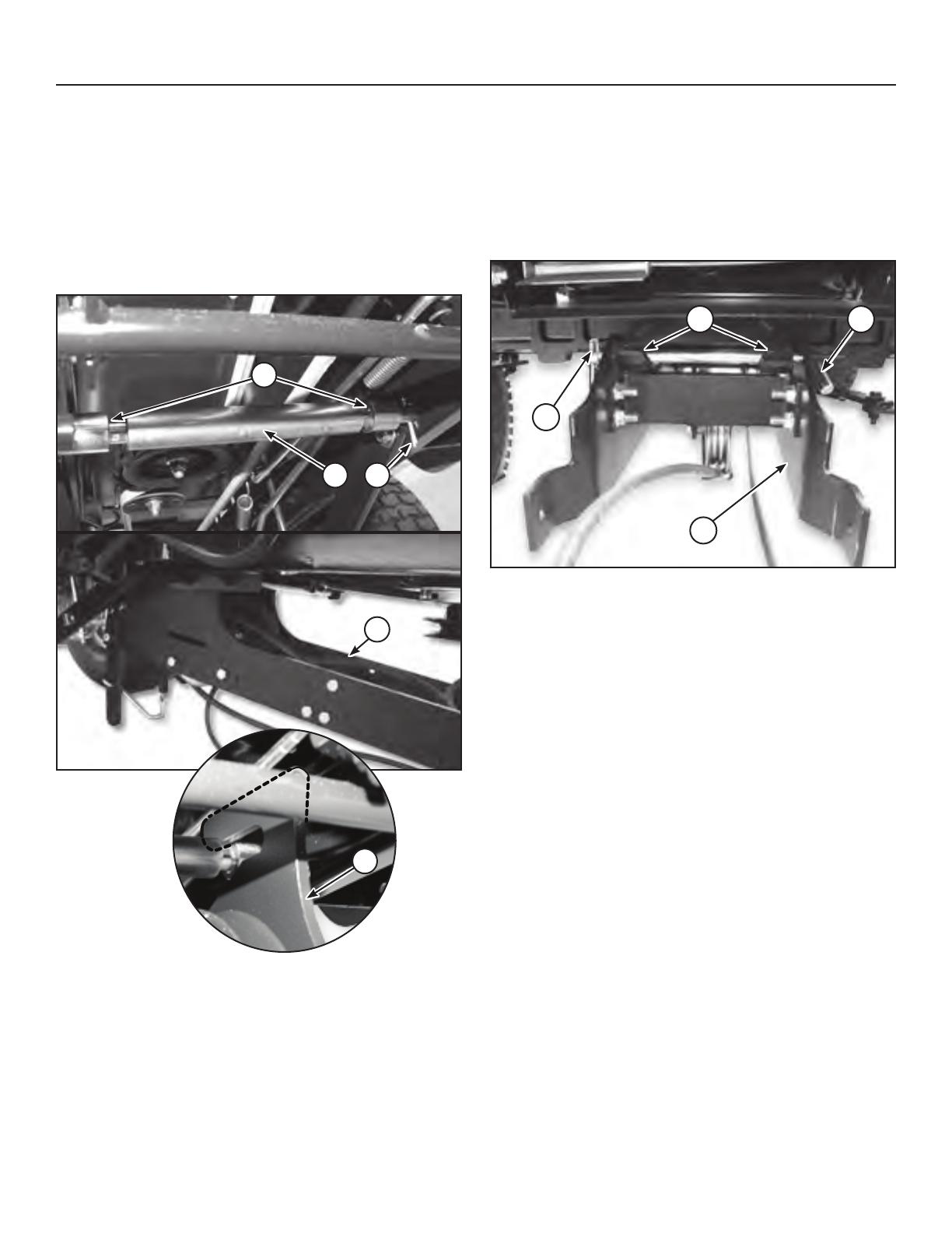
5. Rotate the belt tension lever (e, Figure 11) upwards and
towards the back of the tractor into the locked position
(f).
e
f
Figure 11
Attach Lift Arm Assembly to Tractor
1. On right side of tractor, remove the four (4) hex bolts (a,
Figure 12) and nuts from hitch assembly.
a
Figure 12
Assembly
Attach Snowthrower to Tractor
1. Position snowthrower assembly in front of tractor.
2. Remove both saftey clips and mounting pins from the
snowthrower.
NOTE: Mounting pins and safety clips come pre-
assembled to snowthrower assembly.
3. Align the hitch assembly mounting arms with the
snowthrower mounting tabs, insert mounting pins (a,
Figure 9) and secure with safety clips (b).
a
b
Figure 9
4. Install the drive belt onto the snowthrower drive pulley
(c, Figure 10) and then onto the tractor PTO pulley (d).
d
c
Figure 10

Not for
Reproduction
13
2. Attach lift arm assembly (H, Figure 13) to the tractor
frame using the four hex bolts (b) and nuts from the
previous step.
H
b b
Figure 13
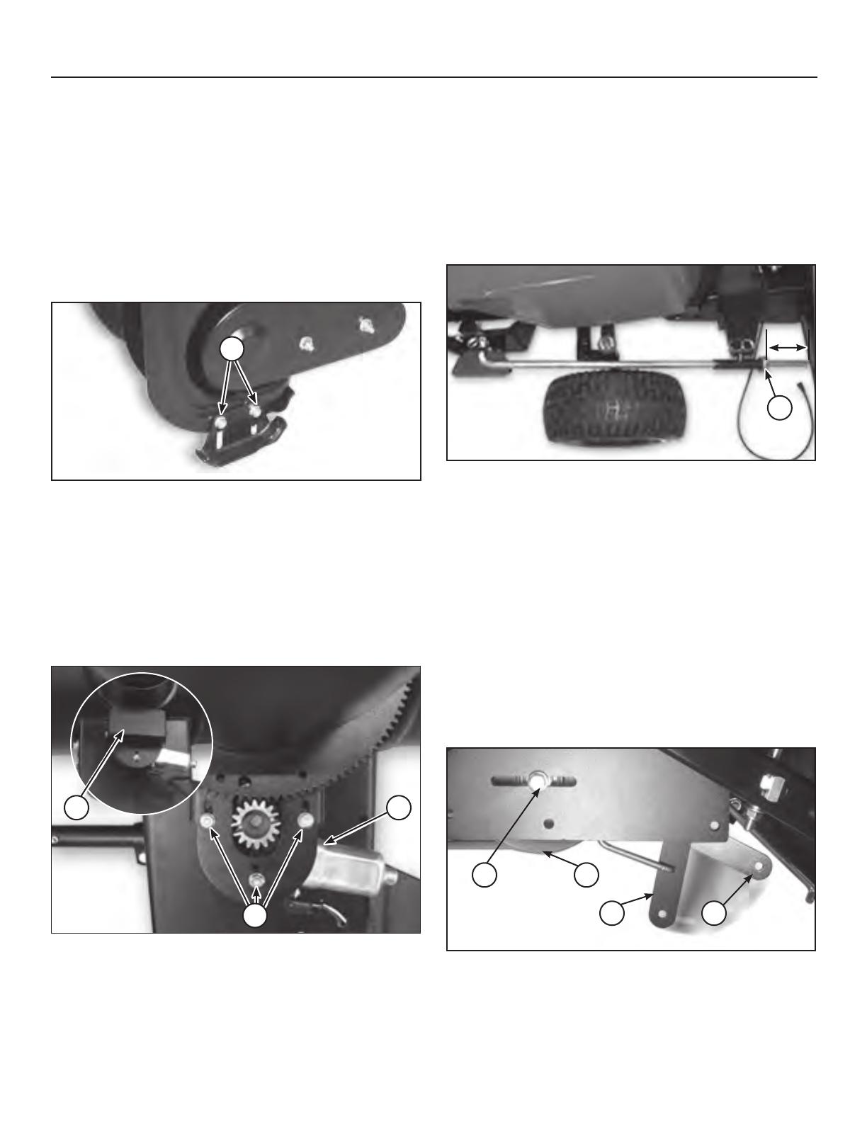
3. Install lift rod assembly (I, Figure 14) and secure with
safety clips (J).
4. Using lift arm, fully raise snowthrower off the ground
into locked position. Distance from the collar to end of
rod should be 3.75”. If not, lower the snowthrower to the
ground and adjust the lifting collar (c, Figure 14).
NOTE: The distance from ground to the snowthrower
should be 4” - 5” when snowthrower is in fully raised
and locked position.
3.75
”
I
c
J
Figure 14
Assembly
5. Assemble lift assist parts. Attach spring (K, Figure 15)
to turnbuckle (L) and axle clamp (M).
NOTE: Do not position the axle clamp over the axle rib.
L K M
Figure 15
6. Fully raise the snowthrower off the ground.
7. On the left side of tractor attach turnbuckle (L, Figure
16), spring (K) and axle clamp (M) onto snowthrower
assembly eyebolt (d).
Ld K M
Figure 16
8. Adjust spring tension by rotating the turmbuckle (L,
Figure 17) clockwise using a 9/16” wrench, until threads
are no longer visible.
L
Figure 17
Not for
Reproduction
14
Assembly
Attach Chute Motor Wiring Harness
(Non-Electric Deck Lift Models)
NOTE: Open hood on tractor for installing the wire harness.
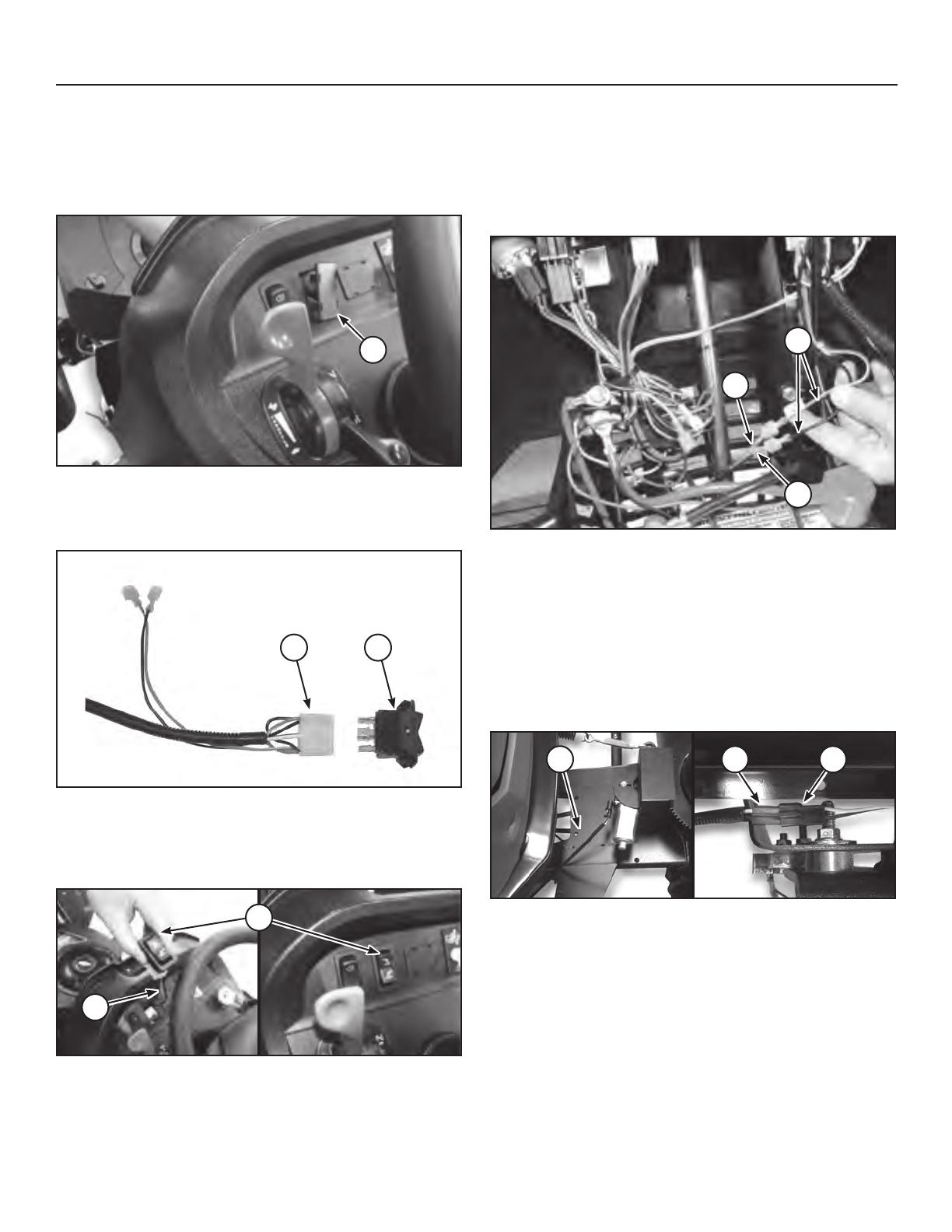
1. Remove plug from tractor dashboard (a, Figure 18).
a
Figure 18
2. Plug female connector of the upper wiring harness (N,
Figure 19) into switch (O).
N O
Figure 19
3. Route the upper wiring harness (N, Figure 20) and
switch (O) through opening in dashboard. Snap switch
into dashboard to secure.
N
O
Figure 20
4. Locate the tractor power leads (Figure 21), red with
yellow stripe (b) and black (c), at the base of steering
column. Connect these leads, color to color, to the
upper wiring harness (N).
IMPORTANT: DO NOT use yellow and black power
tractor lead.
N
b
c
Figure 21
5. Route the upper wiring harness along the right side of
the tractor.
6. Connect the chute rotation wiring harness (d, Figure 22)
from the snowthrower to the square black plug from the
upper wiring harness (e). Position the wiring heat cover
underneath the muffler.
NOTE: Wire harness (d) may be in hardware bag or
connected to snowthrower.
d e d
Figure 22
Not for
Reproduction
15
Assembly
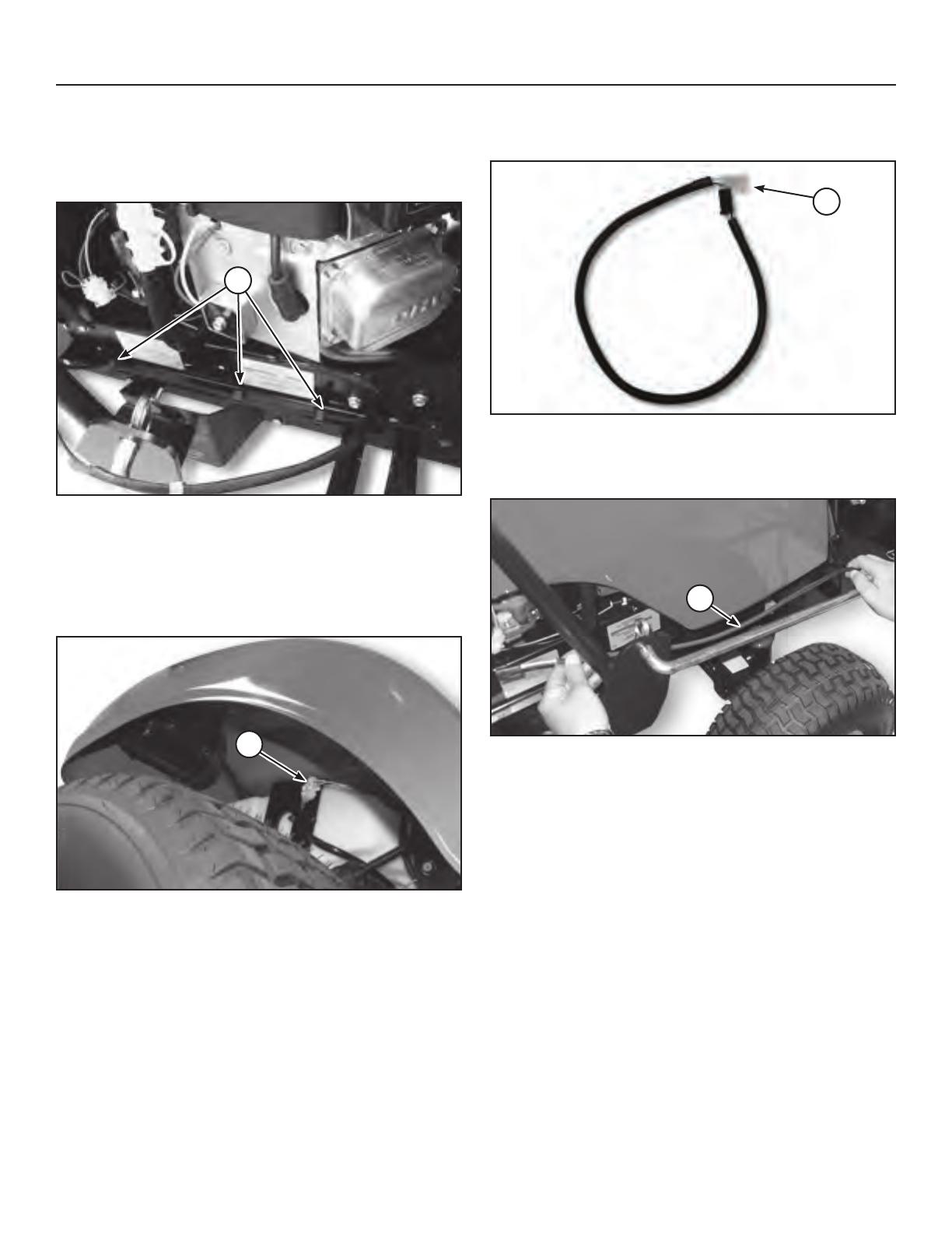
7. Secure wiring harness in place with clips (P, Figure 23)
to the frame rails.
NOTE: Wire harness slack should be secured and not
interfere with moving parts.
P
Figure 23
Attach Chute Motor Wiring Harness
(Electric Deck Lift Models)
1. Under right rear fender, locate and disconnect the
electric height of cut motor plug (a, Figure 24).
a
Figure 24
2. Plug white female connector end of 26” extension wire
harness (R, Figure 25) into existing tractor wire harness.
R
Figure 25
3. Route chute rotation wire harness (a, Figure 26) along
the frame rail.
b
Figure 26
Not for
Reproduction
16
Assembly
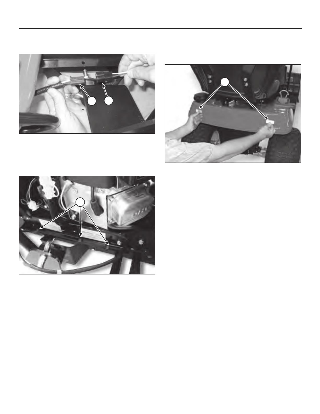
4. Connect chute rotation wire harness (c, Figure 27) to
the 26” extension wire harness (R).
c
R
Figure 27
7. Secure wiring harness in place with clips (P, Figure 28)
to the frame rails.
NOTE: Wire harness slack should be secured and not
interfere with moving parts.
P
Figure 28
Install Reectors
Install the two reflectors (Q, Figure 29) on the rear of the
tractor seat deck
Q
Figure 29

Not for
Reproduction
17
Operation
WARNING
If auger does not start and stop when engaging/
disengaging electric clutch, see your authorized
dealer. Under no circumstances should you attempt to
defeat the safety system.
Checks Before Starting
1. Refer to the Maintenance & Adjustments sections of this
manual and perform any needed service. Also, refer to
the tractor Operator’s Manual and perform any required
service.
2. Remove any objects from the work area which might be
caught in, or thrown by, the auger.
3. Before starting the engine, clear the auger of any ice
particles which may cause damage to auger.
4. Adjust the deflector and skid shoes to desired height.
See Skid Shoe Adjustment and Deflector Adjustment.
5. Make sure all hardware is present and secure.
Engine & Ground Speed Selection
Starting and Stopping
1. Start the tractor engine. After a brief warmup, set engine
throttle FULL.
2. Lower the snowthrower.
3. Engage the electric clutch switch. Snowthrower auger
should rotate. Disengage the electric clutch switch.
Snowthrower auger should stop.
4. Adjust the throttle to full speed. Select the proper
ground speed.
5. To stop tractor movement, depress the clutch/brake
pedal. To stop the snowthrower, disengage the electric
clutch. Before leaving the seat, disengage the electric
clutch, set the parking brake, stop the engine, remove
the key, and wait for all moving parts to stop.
WARNING
Perform the Safety System Interlock test found in your
tractor Operator’s Manual. If tractor does not pass the
test, do not operate the tractor. See your authorized
dealer. Under no circumstances should you attempt to
defeat the safety system.
Use caution when clearing a snow covered area.
Snow can cover objects such as curbs, drop-offs,
and other obstacles. Be familiar with the area you are
clearing.
To prevent an explosion or fire, never store the tractor
with fuel in the tank inside a building where an ignition
source is present.
NOTE: Always raise the snowthrower before turning or
backing up to prevent damage to the unit.
DANGER
OPERATING ON SLOPES CAN BE DANGEROUS
Never operate on slopes greater than 17.6% (10°) which
is a rise of 3-1/2 feet (106cm) vertically in 10 feet (607cm)
horizontally.
Operate the unit at a slow ground speed when driving
onto slope. Avoid using brakes to control ground speed.
When operating on slopes that are greater than 15 %
(8.5°) but less than 17.6%, use additional wheel weights
or counterweights.
In addition to counterweights, use extra caution when
operating on slopes. Drive UP and DOWN the slope,
never across the face, use caution when changing
directions and DO NOT START OR STOP ON SLOPE.
For additional traction, tire chains and a weight box can
be added. Maximum weight added to tractor should
not exceed 50 lbs. per wheel and 100 additional lbs. in
weight box.
Transporting
1. Disengage the electric clutch and then raise the
snowthrower.
2. Adjust ground speed according to surface conditions.
3. Select a low ground speed when transporting on a
slippery surface.

Not for
Reproduction
18
Operation
Daily Storage
1. Run the snowthrower a few minutes after blowing snow
to prevent freeze-up of auger.
2. Allow tractor engine to cool before storing in any
enclosure.
O-Season Storage
1. Remove snowthrower from the tractor.
2. Use water pressure or a brush to thoroughly clean the
housing.
3. Paint, or lightly coat with oil, any area where paint has
been worn or chipped away.
4. Lubricate the snowthrower.
5. Store the snowthrower and hitch in a dry place.
Snow Removal Suggestions
• Determine the best snow removal pattern before
beginning.
• Wind direction is an important factor to consider. Rotate
the spout to discharge snow downwind.
• Plan the pattern so that you avoid throwing snow on
cleared areas and on yourself as you are operating.
• When land contour permits, it is best to travel in the
longest direction to minimize turning.
• In very deep or heavy snow, it may be necessary
to make the first pass with snowthrower partially
raised, backing up every few feet and lowering the
snowthrower to clear the snow left on the surface. Also,
it may be necessary to slice off less than the full width of
the auger or reduce ground speed.
• If snow stops flowing freely from the spout, back away
until the snowthrower clears itself.
DANGER
Do not clean out discharge chute with hands.
Contact with moving parts inside chute will cause
serious injury. Use a clean out tool. Use the following
procedure to remove objects or clear the chute:
1. Stop the engine. Remove key.
2. Wait 10 seconds to be sure the auger/impeller blades
have stopped rotating.
3. Alway use a clean-out tool. DO NOT use your hands.
DANGER
Amputation hazard
The discharge chute
contains a rotating impeller
to throw snow. Fingers can
quickly become caught in
the impeller. Never clear or
unclog the discharge chute
with your hands. Always
use a clean-out tool.
Failure to observe these safety instructions will
result in traumatic amputation or severe laceration.
Hand contact with the rotating impeller inside the
discharge chute is the most common cause of injury
associated with snowthrowers. Never use your hands to
clean out the discharge chute.
To safely clear a clogged discharge chute, follow
these instructions:
1. Shut OFF the engine.
2. Wait 10 seconds to be sure the impeller blades have
stopped rotating.
3. Always use a clean-out tool, not your hands.
Storage

Not for
Reproduction
19
Troubleshooting
CAUSE/SOLUTION
A. Electric clutch not engaged. Engage electric clutch.
B. Foreign material is blocking auger. STOP engine. Remove key. Unplug auger with
a clean-out tool. Read WARNING on page 8.
C. Drive chain broken. See authorized dealer.
D. Electric clutch brake not operating properly. See dealer. DO NOT OPERATE.
E. Shear pin(s) broken. Replace with genuine replacement part.
A. Electric clutch brake not operating properly. See dealer. DO NOT OPERATE.
A. Engine RPM too slow. Set throttle to FULL.
B. Ground speed too fast. Use slow ground speed.
C. Snowthrower discharge chute clogged. STOP engine. Remove key. Unplug
discharge chute with a clean-out tool. Read WARNING on page 8.
A. Skid shoes not properly adjusted. Adjust skid shoes.
B. Lift height out of adjustment. See LIFT ROD ADJUSTMENT.
C. No down pressure. See LIFT ROD ADJUSTMENT.
A. Skid shoes not properly adjusted for ground surface. Adjust skid shoes.
B. Too much downward pressure on snowthrower. Raise snowthrower slightly.
A. Tractor too light at rear wheels. Use Quick Tach weights, wheel weights, and tire
chains.
A. Rotator gears out of adjustment.
B. Wire harness disconnected.
Troubleshooting Chart
While normal care and regular maintenance will extend
the life of your equipment, prolonged or constant use may
eventually require that service be performed to allow it to
continue operating properly.
The troubleshooting guide below lists the most common
problems, their causes and remedies.
See the information on the following pages for instructions
on how to perform most of these minor adjustments
and service repairs yourself. If you prefer, all of these
procedures can be performed for you by your local
authorized dealer.
WARNING
To avoid serious injury, perform maintenance on the
tractor or snowthrower only when the engine is stopped
and the parking brake engaged.
Always remove the ignition key and disconnect the spark
plug wire before beginning the maintenance, to prevent
accidental starting of the engine.
PROBLEM
1. Snowthrower auger does not
rotate.
2. Auger does not stop when
electric clutch is disengaged.
3. Auger rotates, but snow is not
thrown far enough.
4. Scraper bar does not clean
down to hard surface.
5. Snowthrower picks up and
throws stones on gravel drive.
6. Tractor does not have
sufficient traction.
7. Chute does not rotate.
Not for
Reproduction
20
Skid Shoe Adjustment
On smooth surfaces such as concrete or asphalt, the
scraper bar should scrape the surface. On surfaces such as
gravel, the scraper bar should be set high enough so that it
will not pick up debris.
1. Loosen the nuts securing the skid shoes (a, Figure 31).
2. Raise or lower the scraper bar to the desired height.
Use wood blocks to hold the snow thrower in position.
3. Set the skid shoes so that they are in contact with the
ground and tighten the skid shoe nuts.
a
Figure 31
Electric Chute Rotator Gear
1. Remove the cover (a, Figure 32) and loosen the three
screws (b) securing the electric chute rotator motor (c).
2. Adjust the motor so that the gear meshes with the
discharge chute ring gear and tighten the adjustment
screws.
3. Reinstall the cover.
a c
b
Figure 32
Troubleshooting
Lift Adjustment
In the fully raised position the attachment should be 4”-5”
off the ground.
1. Fully raise the attachment lift. The snowthrower should
be approximately 4”-5” off the ground. If not, go to step
2.
2. Lower the snowthrower and adjust the front set collar (a,
Figure 33) to achieve the correct lift height.
3.75
”
a
Figure 33
Belt Tension Adjustment
Adjust belt tension if the tension lever does not adjust belt
tension properly.
1. Move belt tension lever to the released position (a,
Figure 34).
2. Loosen bolt (b) on idler pulley (c), located on the left
side of the hitch assembly.
3. Move idler pulley backwards or forwards to adjust snow
thrower drive belt tension.Tighten bolt (b)
4 Move belt tension lever to the locked tension position
(d).
5. Test snowthrower and repeat adjustment as needed.
b c
a d
Figure 34
/