Page is loading ...

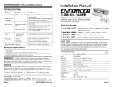
880 LB
ELECTROMAGNETIC LOCK

RADIOCONTROLLED 880 lb MAGLOCK
3 . More features
Direct or wireless transmitter memorisation
Full memory erasure
Single transmitter cancelling
C-NO or C-NC output contact ( selectable )
Direct magnet unlock with C-NO push-button
1. Introduction
. kcolgam roodkcolgam dellortnocoidar ehT
The maglock release command can be sent or by radio, with a 2 key transmitter type 433TSPW2V or a 4 key transmitter type 433TSPW4V ( fig.
1), or using an external C-NO push-button ( not provided ). The magnet unlock starts at the release of the button and lasts the programmed time
( par. 8) : default unlock time = 4 sec. NOTE : a short applied at the C-NO inputs can keep the magnet always unlocked.
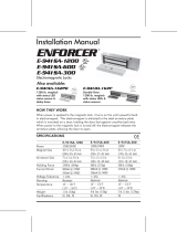
The maglock is equipped with a monitor output R-R ( C-NO or C-NC selectable with a jumper), see image below.
MAGLOC880 is a 880 lb (400Kg) radiocontrolled
P1
2 . Technical specifications
Current consumption ............................................550 mA
Power supply........................................................12 Vdc
Electromagnetic lock dimensions (L xWxD): ............10" x 1.96" x 1.06"
Armature dimensions .........................................7.28" x 1.77" x 0.47"
Operating frequency.............................................433,92 Mhz
Modulation .........................................................AM/ASK
Memory ............................................................10 TX
Default unlock time...............................................4 sec.
Programmable unlock time range...........................1 - 10 sec.
Operating temperature .........................................24 °F 158 °F÷
LOCKED = L1+L2 RED
OPEN = L1+L2 GREEN
STATUS COLORS
4.How it works (Fig. 2)
ABAB
CD
433TSPW2V 433TSPW4V
COMPATIBLE TRANSMITTERS
LOCKED = L1+L2 RED
OPEN = L1+L2 GREEN
4 SEC. ( Default )
LOCKED = L1+L2 RED
Fig. 2
Fig. 1
12 Vdc
LED L1
LED
L2
R
R
C-NO C-NC

5.Transmitter memorisation
5.1 Memorising with P1 push-button (Fig. 3)
1) Push P1 for 4 sec. until L1+L2 turns OFF
2) Push the transmitter button to memorise, L1+L2 will flash and come back OFF, the magnet will have a pulse of UNLOCK. While L1+L2 are
OFF it’s possible to memorize more TX buttons.
After 5 sec. from the last memorisation L1+L2 turn back ON , the procedure ends and the magnet LOCKS AGAIN.
Fig. 3
A
L1+L2 = TURNS OFF
L1 + L2 = ON L1+L2 = SHORT FLASH THEN OFF
PULSE OF UNLOCK
TO THE MAGNET
5 SEC
L1 + L2 = ON
MAGNET LOCKS AGAIN
4 SEC
7 . Memory erasure
7.1 Single transmitter cancelling (Fig. 4)
The procedure to cancel the single transmitter is the identical to the memorisation and carried out only by using P1.
Follow the steps 1 and 2 of the procedure at paragraph 5.1
If the transmitter was memorised, at the end it will be cancelled.
7.2 Full memory erasure ( Fig. 5)
1) Push P1 and keep it pushed until L1+L2 turn OFF;
2) Release P1 and then, before L1+L2 turn on again, keep pushed P1 until L1+L2 make 3 long flashes
At that point the memory has been completely erased.
Fig. 5
5.2 Wireless memorising ( without accessing P1) (Fig. 4)
1) Push simultaneously the buttons A +Bof the transmitter and the led L1+L2 will makeaSHORT FLASH.
2) Release A+B and push the A until the led L1+L2 TURN OFF
3) Release A and push the of the transmitter to memorise ( A orBor C or D)always the led L1+L2 turn ON AGAIN. L1+L2 makeashort
flash, the magnet unlock forawhile and remains OFF, waiting for more buttons to receive. Then, after4sec., L1+L2 turn back ON, the magnet locks
again and the procedure ends. To memorise more transmitters it is necessary to useatransmitter already memorised for opening the memory.
push the button of the new transmitter to
memorise.
button for 4 SEC.
button
Repeat the steps 1 and2above, using the transmitter already memorised. When the led L1+L2 turns OFF
before
A+B AA or B or C or D
L1+L2 = SHORT FLASH
4 SEC.
L1+L2 = OFF L1+L2 = SHORT FLASH THEN OFF
MAGNET UNLOCKS
L1+L2 = SWITCH OFF
L1+L2 = ON
4 SEC
RELEASE P1
L1+L2 = OFF L1+L2 = 3 LONG FLASHES
6 . Full memory
When the memory is full and you try to memorise another transmitter, the led L+L2 make 3 flashes and the operation fails.
Fig. 4
L1+L2 = OFF
KEEP PUSHED

8. Unlock time setting( fig. 6)
The unlock time of the magnet is set by default to 4 sec. To modify this time proceed as follows:
3) For setting the time desired, count the number of flashes and push P1 just after the flash corresponding to the release seconds desired.
At the P1 release, the system will store the time corresponding to the number of flashes: L1 makes 3 short flashes and turns back ON.
NOTE : the 10th flash lasts more then the others.
1) Push simultaneously the buttons A +Bof the transmitter and the led L1 will makeaSHORT FLASH.
2) Release A+B and push the button B for 4 SEC. until the led L1 starts a SEQUENCE OF FLASHES
ESAMPLE : Push P1 here to set a time of 3 seconds
1 Sec. 1 Sec. 1 Sec. 1 Sec. 1 Sec.
1 Sec.
A+B
B
L1+L2 = SHORT FLASH
4 SEC.
L1+L2 = 3 SHORT
FLASHES
Sequence of 10 flashes of L1+L2
Fig. 6
L1+L2 = SEQUENCE
OF FLASHES
APPROVAL RELATIVE TO EMERGENCY EXITS:
In the case of an installation of electromagnetic lock on emergency exits, it is imperative to make sure that these exit points will be
automatically free in case of fire alarm, to open in the event of a fire alarm to allow evacuation of the premises.
The electromagnetic lock installed on emergency exits must be in accordance with the fire approval department
For more information, contact the local fire officer or the safety officer responsible for the building.
POWER SUPPLY
MOUNTING RECOMMENDATIONS
An electromagnetic lock always operates in DC current, a very low safety voltage. The Electromagnetic Lock is recommended
for use with power supplies manufactured by Transmitter Solutions, however, other power supplies may be used on condition
that they are of equivalent quality and characteristics rectified, filtered, regulated and protected by fuse in primary and
secondary sectors.
- Define the level of security of the access.
- Determine the maximum strength of holding force to this level of security.
- Select the Electromagnetic Lock according to the environment, the inside, the outside, the climatic constraints,
(For example: stainless steel dedicated to an outside use).
- Always install the electromagnetic lock on the secure side of the place to be secured.
- Indeed make sure that the frame and opening, receiving or supporting the electromagnetic lock, armature plate and their
accessories, are solid and resistant to damage or wear over a period of time.
- Consider any bracketry required for the assembly according to the type of support receiving the electromagnetic lock and
armature plate.
- Define the passage of cables to ensure the protection against the vandalism and the environmental requirements (in particular
through flexible hoses of door, glands, gutters, cross cables, plastic tubes).

Armature plate
- It is vital to fix the electromagnetic lock and armature plate solidly
on their supports.
- Make sure that the magnet and the armature meet evenly over
their entire mating surfaces.
- The Armature plate must be able to pivot slightly about its center
mounting screw to compensate for any door misalignment.
Security ropes
The electromagnetic lock undergoes repeated shocks and the
vibration at the points of fixation on the frame (frequencies of
openings / closures, attempt of opening wears closed and
attempts of vandalism) which can loosen the fixing bolts/
screws. To prevent the risk of the electromagnetic block from
falling, install both security ropes supplied, to guarantee the
safety of the users (see attached plan).
MAINTENANCE
The Electromagnet and armature plate have a specific treatment which strengthens the protection against wear and corrosion.
These products do not require high maintenance. Nevertheless to ensure optimum performance,it is recommended to clean
regularly the surfaces in contact of the electro magnet and armature plate with a cloth and non abrasive products. If traces of
corrosion appear, it is recommended to clean and oil the contact surfaces.
Check and tighten regularly all the fixings of the Electromagnet and ensure that while the armature is able to pivot on its mou nting,
the fixing bolt is not liable to loosen (we recommend thread-lock for all fixing bolts).
Security rope
(fixing on the magnetic lock and the frame)
INSTALLATION
Installation on an outward opening door (Push door) Installation on an inward opening door (Pull door)

INSTALLATION WITH ACCESSORIES
Installation with an Armature housing Installation with base for glass door
Armature housing for glass door
Installation with DPM300 - DPM400 - DPM500 (Door position
monitoring)*
DPM
Fixed on the electromagnetic lock
300
DPM Fixed on the armature300
Roll pin
Armature plate Electromagnetic lock

The warranty period of Transmitter Solutions magnetic locks is twenty-four (24) months. This warranty shall begin on the date the
keypad is manufactured. During the warranty period, the product will be repaired or replaced (at the sole discretion of Transmitter
Solutions) if the product does not operate correctly due to a defective component. This warranty does not extend to (a) the case,
which can be damaged by conditions outside the control of Transmitter Solutions, or (b) battery life. This warranty is further limited by
the following disclaimer of warranty and liability:
EXCEPT AS SET FORTH ABOVE, TRANSMITTER SOLUTIONS MAKES NO WARRANTIES REGARDING THE GOODS, EXPRESS OR
IMPLIED, INCLUDING WARRANTY OF MERCHANTABILITY OR WARRANTY OF FITNESS FOR A PARTICULAR PURPOSE. BUYER
MAKES NO RELIANCE ON ANY REPRESENTATION OF TRANSMITTER SOLUTIONS, EXPRESS OR IMPLIED, WITH REGARD TO THE
GOODS AND ACCEPTS THEM “AS-IS/WHERE-IS”. TRANSMITTER SOLUTIONS SELLS THE GOODS TO BUYER ON CONDITION
THAT TRANSMITTER SOLUTIONS WILL HAVE NO LIABILITY OF ANY KIND AS A RESULT OF THE SALE. BUYER AGREES THAT
TRANSMITTER SOLUTIONS SHALL HAVE NO LIABILITY FOR DAMAGES OF ANY KIND, WHETHER DIRECT, INCIDENTAL OR
CONSEQUENTIAL DAMAGES, INCLUDING INJURIES TO PERSONS OR PROPERTY, TO BUYER, ITS EMPLOYEES OR AGENTS, AS
A RESULT OF THE SALE. BUYER ALSO AGREES TO HOLD TRANSMITTER SOLUTIONS HARMLESS FROM ANY CLAIMS BUYER,
OR ANY THIRD PARTY, MAY HAVE AS A RESULT OF BUYER’S USE OR DISPOSAL OF THE GOODS. BUYER HAS READ THIS
DISCLAIMER AND AGREES WITH ITS TERMS IN CONSIDERATION OF RECEIVING THE GOODS.
WARRANTY:

/