Page is loading ...

1
TA 500 Rev. 10 en 09/2017 Subject to technical modications! www.sera-web.com
PolyLine® Flow
Operating instructions
PolyLine® Flow ... S
PolyLine® Flow ... L
PolyLine® Flow ... SL
Manufacturer:
sera GmbH
sera-Straße 1
34376 Immenhausen
Germany
Tel.: +49 5673 999-00
Fax: +49 5673 999-01
www.sera-web.com
Keep the operating manual for future use!
Record the exact type and serial number here.
(can be read off the type plate on the dosing unit)
Type :
Serial No. :
These data are important in the case of queries or for ordering spare and/or wear
parts and must always be stated.
Translation of the original operating instructions!

2www.sera-web.com Subject to technical modications! TA 500 Rev. 10 en 09/2017
PolyLine® Flow
Operating instructions

3
TA 500 Rev. 10 en 09/2017 Subject to technical modications! www.sera-web.com
PolyLine® Flow
Operating instructions
Project-specic documents such as product description and test certicates are not an
integral part of the CD contents.
NOTE!
Technische Dokumentation
Technical Documentation
Deutsch / English
www.sera-web.com
sera GmbH
sera-Straße 1
34376 Immenhausen
Germany
PolyLine®
Typen / types:
Flow 500 - 8000
Swing 500 - 4000
Double 500 - 2000

4www.sera-web.com Subject to technical modications! TA 500 Rev. 10 en 09/2017
PolyLine® Flow
Operating instructions
Table of contents
1. General information ..................................................................................................................................6
1.1 General user instructions .....................................................................................................................6
1.2 Marking of notes in this operating manual ............................................................................................6
1.3 Marking of notes on the product ...........................................................................................................6
1.4 Quality notes ........................................................................................................................................7
1.5 Utilities ..................................................................................................................................................7
1.6 Water quality......................................................................................................................................... 7
1.7 Design data ..........................................................................................................................................7
2. Safety instructions ....................................................................................................................................8
2.1 Personnel qualication and training .....................................................................................................8
2.2 Dangers in the case of non-observance of the safety instructions .......................................................8
2.3 Safety conscious working .....................................................................................................................8
2.4 Safety instructions for the owner / operator ..........................................................................................8
2.5 Safety instructions for maintenance, inspection and installation work ................................................. 8
2.6 Unauthorised modication ....................................................................................................................8
2.7 Improper operation ............................................................................................................................... 9
2.8 Intended use .........................................................................................................................................9
2.9 Personal protection equipment for maintenance and repair .................................................................9
2.10 Foreseeable misuse ......................................................................................................................... 10
2.10.1 Transport ..................................................................................................................................10
2.10.2 Installation ................................................................................................................................10
2.10.3 Commissioning .........................................................................................................................10
2.10.4 Operation ................................................................................................................................. 11
2.10.5 Maintenance / repair ................................................................................................................ 11
2.10.6 Cleaning ................................................................................................................................... 11
2.10.7 Dismantling .............................................................................................................................. 11
2.10.8 Disposal ................................................................................................................................... 11
2.10.9 Decommissioning ..................................................................................................................... 11
3. Transport and storage ............................................................................................................................12
3.1 General ...............................................................................................................................................12
3.2 Transport ............................................................................................................................................ 12
3.3 Storage ...............................................................................................................................................12
4. Product description ................................................................................................................................13
4.1 Types .................................................................................................................................................. 13
4.1.1 Type code ...................................................................................................................................13
4.1.2 Type plate ...................................................................................................................................13
4.1.3 Materials .....................................................................................................................................14
4.2 Functional description ........................................................................................................................14
4.3 Supply unit design .............................................................................................................................. 16
4.4 Options ...............................................................................................................................................17
5. Technical Data .........................................................................................................................................18
5.1 Technical Data .................................................................................................................................... 18
5.2 Electrical data .....................................................................................................................................18
5.3 Dimensions .......................................................................................................................................19
5.3.1 PolyLine® Flow ... SL ................................................................................................................. 19
5.3.2 PolyLine® Flow ... L ...................................................................................................................20
5.3.3 PolyLine® Flow ... S ................................................................................................................... 21
6. Assembly / Installation ............................................................................................................................ 22
6.1 Installation ..........................................................................................................................................22
6.2 Installation location .............................................................................................................................22
7. Electrical connection ..............................................................................................................................23

5
TA 500 Rev. 10 en 09/2017 Subject to technical modications! www.sera-web.com
PolyLine® Flow
Operating instructions
8. Control system ........................................................................................................................................23
8.1 General operating instructions ...........................................................................................................23
8.1.1 Touch panel operation ...............................................................................................................24
8.2 Start screen ........................................................................................................................................ 25
8.3 Automatic mode ..................................................................................................................................26
8.3.1 Process control ..........................................................................................................................27
8.4 Parameters ........................................................................................................................................28
8.4.1 Settings (parameter) ..................................................................................................................32
8.5 Service mode .....................................................................................................................................33
8.6 Setup mode ........................................................................................................................................ 36
8.6.1 Water ow rate adjustment .........................................................................................................37
8.6.2 Hopper empty signal empty adjustment (option) ........................................................................37
8.6.3 Hopper empty signal full adjustment (option) ............................................................................. 38
8.6.4 DMF (dry material feeder) calibration .........................................................................................38
8.6.5 Calibration pump ........................................................................................................................40
8.7 Summation counter ............................................................................................................................40
8.8 System settings .................................................................................................................................. 42
8.9 Error messages ................................................................................................................................. 44
8.10 Exchange of signals ........................................................................................................................45
9. Commissioning ......................................................................................................................................46
9.1 Function description of wide angle nozzle ..........................................................................................48
10. Maintenance ...........................................................................................................................................49
11. Decommissioning ..................................................................................................................................51
12. Restarting ...............................................................................................................................................51
13. Fault analysis and corrective action ...................................................................................................51
14. Disposal .................................................................................................................................................51
14.1 Removal and transport ..................................................................................................................... 52
14.2 Complete disposal ............................................................................................................................52
15. Documentation of the system parts ....................................................................................................52
16. Clearance Certicate .............................................................................................................................53

6www.sera-web.com Subject to technical modications! TA 500 Rev. 10 en 09/2017
PolyLine® Flow
Operating instructions
1. General information
1.2 Marking of notes in this operating manual
1.1 General user instructions
The applicable regulations for the installation site must be observed before the commissioning and during the opera-
tion of this sera product.
This sera product is delivered ready for connection. Carefully read these instructions and particularly the safety in-
structions before installation and commissioning.
Special notes in these operating instructions are marked with text and danger symbols.
Designation of the note Danger type Denition of the note
(Text and symbol)
Danger of fatal injury
Risk of injury
Damage to property
(in the operating instructions)
DANGER! XXX
Identies an imminent danger
that results in fatal or severe injuries if not
avoided.
WARNING! XXX
Designates a potentially dangerous situation
There might be danger to life or serious injury and
damage to property if it is not avoided.
CAUTION! X X
Designates a potentially dangerous situation
There might be slight or minor injury or damage to
property if it is not avoided.
ATTENTION! X
Designates a potentially dangerous situation
that could lead to damage to property if not
avoided.
NOTE! Designates information which helps to make work
easier and is useful for trouble-free operation.
1.3 Marking of notes on the product
Symbols which are directly attached to the pump, e.g. arrows for direction of rotation or symbols for uid connections
are to be observed and kept in legible condition.

7
TA 500 Rev. 10 en 09/2017 Subject to technical modications! www.sera-web.com
PolyLine® Flow
Operating instructions
1.5 Utilities
If not agreed otherwise in the contract conditions, the sera dosing station will always be supplied with the necessary
utilities. (Type and quantity of the utilities / lubricants are stated in the operating instructions of the pumps and valves).
1.6 Water quality
Water used for commissioning, maintenance and shutting down must be similar to drinking water, i.e. chemically neu-
tral, free from solid and suspended matter and interfering ion concentrations.
1.7 Design data
Observance of these operating instructions and, in particular, the safety instructions, helps to:
■Avoid dangers to persons, machines and environment.
■Increase reliability and service life of the product and the complete system.
■Reduce repair cost and downtime.
The sera quality management and quality assurance system for pumps, systems, valves and ttings and compres-
sors is certied according to ISO 9001:2008.
The sera product meets the valid safety and accident prevention regulations.
Always keep these operating instructions within reach at the place of installation.
ATTENTION!
Pay attention to the safety data sheet of the medium! The owner must take cor-
responding accident prevention measures to protect operating personnel from
danger through the delivery media used!
WARNING!
Medium End product polymer solution max 1%
Viscosity End product max. 500 mPas
Working temperature 5 °C to 40 °C
Solid matter none
Installation indoors, no direct sunlight
Design pressure 1-6 bar water pressure (depressurised tank)
1.4 Quality notes

8www.sera-web.com Subject to technical modications! TA 500 Rev. 10 en 09/2017
PolyLine® Flow
Operating instructions
2.6 Unauthorised modication
2.5 Safety instructions for maintenance, inspection and installation work
2.4 Safety instructions for the owner / operator
2.3 Safety conscious working
2.2 Dangers in the case of non-observance of the safety instructions
2.1 Personnel qualication and training
2. Safety instructions
The personnel for operation, maintenance, inspection and installation must be suitably qualied for their tasks. The
owner must clearly dene responsibility and supervision of the personnel.
If the personnel do not have the knowledge required, then personnel is to be trained and instructed correspondingly.
Such training can be provided by the manufacturer / supplier upon order of the owner. In addition, the owner has to
ensure that personnel have understood the operating instructions completely.
Inobservance of these safety instructions can result in danger to persons, hazards to the environment and damage
to the product.
Inobservance of the safety instructions may lead to:
■Failure of important functions of the product/system.
■Inobservance of prescribed methods for maintenance and servicing.
■Danger to persons through electrical, mechanical and chemical inuences.
■Hazards to the environment through leaking dangerous media.
The safety instructions specied in this operating manual, the national regulations for accident prevention, the safety
regulations for the pumped medium valid at the place of installation as well as internal working-, operating-, and safety
instructions of the owner are to be observed.
Leaking hazardous delivery media and operating supplies are to be disposed off in such a way that any danger to
persons and the environment is excluded. The legal regulations are to be observed.
Danger caused by electrical energy is to be avoided.
The owner must ensure that any maintenance-, servicing- and installation work is only entrusted to authorized and
suitably qualied personnel who have carefully read and understood the operating instructions.
Only those spare parts and operating supplies are to be used which meet the requirements of the specied operat-
ing conditions.
Threaded joints and connections may only be disconnected when the system is not under pressure.
Modications of or changements to the pump are only permitted after previous agreement of the manufacturer. Origi-
nal spare parts and accessories which were approved by the manufacturer are essential for safety reasons.

9
TA 500 Rev. 10 en 09/2017 Subject to technical modications! www.sera-web.com
PolyLine® Flow
Operating instructions
2.8 Intended use
2.7 Improper operation
Operating safety of the supplied product is only guaranteed if the product is used as intended, according to the
descriptions in Chapter "Intended use" of these operating instructions.
The sera product is only to be deployed according to the intended purpose stated in the product description and the
acceptance test certicate.
If the product is to be used for other applications, then the suitability of the product for the new operating conditions
must be discussed with sera beforehand!
Criteria for operation in accordance with the intended use:
■Observe characteristics of the medium (please see safety- and product data sheet of the delivery
medium – the safety data sheet is to be provided by the supplier / owner of the medium).
■Resistance of the materials which come into contact with the medium.
■Operating conditions at the place of installation.
■Pressure and temperature of the medium.
■Voltage supply.
If the pumps (e.g. drive motor) are modied without au-thorization of the manufac-
turer or spare parts are used which are not approved, any warranty claim becomes
null and void.
CAUTION!
2.9 Personal protection equipment for maintenance and repair
The provisions of the German Ordinance on Hazardous Substances (GefStoffV) (§14 Safety Data Shee) and relevant
national safety regulations for the pumped medium must strictly be adhered to.
In case of accidents check whether the following substances are emitted:
■Leaking uids.
■Leaking vapours.
■Noise emissions (sound level).
Emissions are to be monitored by corresponding controly systems of the total installation.
Wear protective clothing, gloves, breathing mask and a face protecting mask.
ATTENTION!
Personal protective equipment must be provided by the owner!
NOTE!
NOTE!

10 www.sera-web.com Subject to technical modications! TA 500 Rev. 10 en 09/2017
PolyLine® Flow
Operating instructions
2.10.3 Commissioning
2.10.2 Installation
2.10.1 Transport
2.10 Foreseeable misuse
■Load not sufciently secured during transport.
■Transport by untrained personnel.
■Tipping behaviour during transport, loading and unloading ignored.
■Weight for lifting underestimated.
■Climbing on the system.
The following misuse is assigned to the life cycles of the machine.
Misuse can result in danger to the operating personnel!
DANGER!
■Installation of the system at an improper site (outside, direct sunlight, explosion-hazardous area etc.).
■Confusion of the suction and pressure pipes.
■Threads overturned/damaged.
■Piping bent when it was mechanically connected.
■Non-compliant electrical connection (without ground wire, mains not fuse-protected etc.).
■Inside soiling of the tank.
■Stepping on the tank (e.g. as climbing aid).
■Modication to another tank.
■Installation on an unsuitable surface (e.g. inclined surface).
■Improper fastening (e. g. screwing of the tank bottom).
■Non-observance of the design data/operating conditions (medium, pressure, suction height, temperature
etc.).
■Non-observance of the electrical characteristics (motors, sensors).
■Cover on vent openings (motor).
■Closed suction and pressure pipes.
■Conveyance of a wrong medium.
■Maladjustment/damage of the level meters.
■Too high a back pressure.
■Pumped medium too warm ► failure of material.
■Tank overlled.
■Sensor cable removed.
■Conveyance without connected pressure pipe.
■Test run without cover.

11
TA 500 Rev. 10 en 09/2017 Subject to technical modications! www.sera-web.com
PolyLine® Flow
Operating instructions
2.10.9 Decommissioning
2.10.8 Disposal
2.10.7 Dismantling
2.10.6 Cleaning
2.10.5 Maintenance / repair
2.10.4 Operation
■Operation of the pump/overow valve with defective diaphragm.
■Ignoring of a pump fault.
■Operating the machine outside its designed limits for use.
(exceeding the rated pressure, pressure peaks, contaminated medium (with particles).
■Sudden closure of the pressure pipe.
■Suction pipe clogged.
■Operation with open cover.
■Personnel not familiar with handling of the pump.
■Wrong pumped medium.
■Tank overlled.
■Conveyance without connected pressure pipe.
■Disregard of the maintenance schedule according to the operating instructions.
■Improper maintenance.
■Use of non-original spare parts.
■Insufcient rinsing before maintenance work.
■Use of cables with damaged insulation.
■Valves confused.
■Pipes not connected.
■Protective equipment insufcient or missing.
■Wrong rinsing/cleaning agent.
■Use of unsuitable cleaning utensils.
■Rinsing/cleaning agent residues in the system.
■Tank turned over for discharge.
■Vent openings clogged.
■Repair work by untrained personnel.
■Improper execution of repair work.
■Improper disposal of the pumped medium, consumables and materials.
■Insufcient removal of the pumped medium from the pipes with subsequent rinsing.
■Removal of pipes with the pump running (residual pressure).
■Disconnection from the power supply not ensured.

12 www.sera-web.com Subject to technical modications! TA 500 Rev. 10 en 09/2017
PolyLine® Flow
Operating instructions
3.2 Transport
3.1 General
3. Transport and storage
sera products are checked for faultless condition and function before shipment.
The packaging will be in accordance with the transport conditions. The transport is upright on a pallet.
The products are packed according to the transport conditions. The system is transported upright on
the available grating.
The customer must check the product for transport damage immediately after receipt. If
any damage is detected, this must be reported immediately to the responsible carrier and
to the supplier.
The unit should only be transported using suitable means of transport or hoists.
Pay attention to the weight of the system and the load-bearing capacity.
The accident prevention regulations must be observed for transport and
shunting.
WARNING!
Keep a sufcient distance from high-tension lines when transporting the
system.
DANGER!
Check the system for loose parts.
Fasten loose parts for transport!
WARNING!
Be careful when lifting the system. Pay attention to the centre of gravity!
Fasten the system sufciently! The unit must only be transported using suit-
able lifting gear!
CAUTION!
3.3 Storage
An undamaged packaging protects the unit during storage and should only be opened when the product is installed.
Proper storage increases the service life of the product and includes prevention of negative inuences such as heat,
moisture, dust, chemicals etc.
The following storage specications are to be obsered:
■Storage place: cool, dry, dustfree and slightly ventilated
■Storage temperature between -10°C and +45°C
■Relative air humidity not more than 50 %.
■The maximum storage time for the standard system is 12 months.
If these values are exceeded, metal products should be sealed in foil and protected from condensation water with a
suitable desiccant.
Do not store solvents, fuels, lubricants, chemicals, acids, disinfectants and similar in the storage room.

13
TA 500 Rev. 10 en 09/2017 Subject to technical modications! www.sera-web.com
PolyLine® Flow
Operating instructions
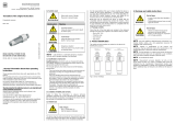
1 2 3 4
4.1.2 Type plate
4.1.1 Type code
4.1 Types
Designation
Unit capacity in L/H
Arrangement of chambers
- Flow (3-chamber unit)
- Swing (2-chamber-swing)
- Double (2-chamber-double)
Polymer
S: Solid
L: Liquid
SL: Solid + Liquid
PolyLine® Flow 500 S (sample)
Every sera dosing station is factory provided with a type plate.
The following information can be found on this type plate.
1Type of the dosing station
2Serial number of the dosing station
3Year of construction of the dosing station
4Pumped medium
4. Product description

14 www.sera-web.com Subject to technical modications! TA 500 Rev. 10 en 09/2017
PolyLine® Flow
Operating instructions
The suitability of the materials for the medium must be ensured by the owner. The following
materials are used:
PP: tank
PVC-U: ball cocks
FPM: tank seal (ball cocks)
Brass: water supply ttings
Stainless steel: DMF case
The preparation of the polymer solution is controlled by a programmable logic controller (PLC) in combination with a
control panel.
The system can be operated automatically or manually. In automatic mode, the preparation is performed completely
automated and/or by external enable. The water quantity needed for the preparation process is set at the valves in
the process water supply. Manual mode is used for service purposes whereby all units can be actuated individually.
For removal chamber (9) of the tank (6), the ll levels are recorded using a continuous ultrasonic sensor (5) and evalu-
ated by the control system (4). The removal chamber can optionally be implemented with overow protection using
capacitive sensors with WHG (German Water Resources law) approval.
System alarm messages are displayed as plain text on the control panel. A distinction is made between warnings and
faults whereby the latter are also signalled by a "group fault" indicator lamp. The messages remain present until they
are acknowledged at the control panel and their causes have been eliminated. There is also a potential-free switching
contact available which wire the group fault of the system on the terminal block.
When using polymer in powder form, the nished solution is realised by adding this using a dry material feeder (DMF)
(3). The feed hopper of the DMF can optionally be tted with a capacitive limit switch to be able to output an "empty"
signal.
In order to prevent lumping or bridging at the two discharge points of the DMF, these are tted with a heating ring
which is always switched on during operation of the system. The polymer dosing is performed proportionally to the
water quantity (dosing pulse) in order to also guarantee an approximately constant concentration of the preparation in
the event of a fault. The dosing pulse here can be set customer-specically to a multiple of the ow sensor. The run-
ning time of the DMF is determined from the preparation concentration and the conveying capacity of the dry material
feeder. The latter requires calibration of the dry material feeder which must strictly be performed individually for both
conveying directions.
The concentrate is produced with a pump when using liquid polymer. The system owner must ensure sufciently
lled delivery containers of the liquid polymer here. In this case, the polymer is added by the injection in proportion to
the water quantity into the piping of the system. The running time of the addition is determined from the preparation
concentration (effective amount of the liquid polymer used) and the delivery rate of the concentrate pump. The latter
requires calibration of the concentrate pump.
The process is started with preparation chamber (7) at the beginning of the automatic preparation. This is rst lled
with an initial charge of water until the ll level of the agitator (2) lock (LSZL) is reached. In the next step, the polymer
addition is started depending on the system variant and is controlled proportionally to the continuous inowing water
quantity.
The prepared polymer solution ows automatically into the maturing chamber (8), the mature product reaches the
removal chamber (9).
As soon as the LS+ ll level in the removal chamber is reached, he addition of polymer and water is stopped and the
preparation complete. The agitators continue to be switched on here until expiry of the maturing time (run-on time)
and then changes to pulse-pause mode which can be parametrised customer-specically. If no pulse / pause time is
set, the agitators remain switched off until the start of a new preparation.
As soon as the MIN-level in the removal chamber is reached again, the new preparation starts automatically.
4.2 Functional description
4.1.3 Materials

15
TA 500 Rev. 10 en 09/2017 Subject to technical modications! www.sera-web.com
PolyLine® Flow
Operating instructions
No. Designation
1 Supply unit
2 Electric agitator MU...
3 Dry material feeder DMF...
4 Control system
5 Continuous ultrasonic sensor
6 Tank
7 Preparation chamber
8 Maturing chamber
9 Removal chamber
4
2
7
3
2
8
1
5
6
9

16 www.sera-web.com Subject to technical modications! TA 500 Rev. 10 en 09/2017
PolyLine® Flow
Operating instructions
No. Designation
1 Gate valve
2 Pressure reducer with manometer
3 Solenoid valve
4 Flow sensor
5 Check valve
6 Ball cock
7 Dosing valve
8 Pump
4.3 Supply unit design
PolyLine® Flow ... SL
1
23
4
1
5
7
8
7
1
PolyLine® Flow ... L
3
2
4
5 5
PolyLine® Flow ... S
1
2
3
4
1
6
1
8

17
TA 500 Rev. 10 en 09/2017 Subject to technical modications! www.sera-web.com
PolyLine® Flow
Operating instructions
4.4 Options
No. Designation
1 Hopper exension *
2 Conveying system *
3 Vibrator *
4 Sensor empty signal for hopper *
5Overow protection
6 Electric agitator
7Overow
8 Sensor full signal for hopper *
* See the operating instructions dry material feeder DMF.
1
2
3
4
5
6
7
8

18 www.sera-web.com Subject to technical modications! TA 500 Rev. 10 en 09/2017
PolyLine® Flow
Operating instructions
5.2 Electrical data
5.1 Technical Data
5. Technical Data
PolyLine®Variant 1) Weight System
volume
Preparation
concentra-
tion
Maturing time Viscosity System
performance
2)
appr. kg L % min mPas L/h
500
S 225
500 0,05...1 45 500 500
L 210
SL 245
1000
S 225
1000 0,05...1 45 500 1000
L 210
SL 245
2000
S 260
2000 0,05...1 45 500 2000
L 240
SL 275
4000
S 440
4000 0,05...1 45 500 4000
L 420
SL 465
8000
S 740
8000 0,05...1 45 500 8000
L 720
SL 765
1)
System variants: S ► Solid polymer, L ► Liquid polymer, SL ► Solid and liquid polymers
2)
depending on polymer and maturing time
Supply voltage Control voltage
Type of protection
Switch cabinet Electrical consumers
3 / 400 V / 50/60 Hz + N +PE 24 V DC IP 54 IP 55

19
TA 500 Rev. 10 en 09/2017 Subject to technical modications! www.sera-web.com
PolyLine® Flow
Operating instructions
N3
N2
N1
N4
N5
N6
H4
H3
85
H2
H
B
L1
L
H1
B5 H5
PolyLine® Flow ... SL
500 1000 2000 4000 8000
standard
B 990 990 990 1280 1570
H 1552 1552 1822 2112 2327
H1 1387 1387 1657 1947 2162
H2 750 750 1020 1310 1525
L 2367 2367 2360 3426 4467
L1 1990 1990 1990 2990 4000
N1 product removal DN25 DN25 DN32 DN40 DN50
N2 tank draining DN25 DN25 DN25 DN25 DN25
N3 tank draining DN25 DN25 DN25 DN25 DN25
N4 water supply DN15 / IG1/2 DN15 / IG1/2 DN15 / IG1/2 DN15 / IG1 DN15 / IG1
N6 polymer supply DN5 (G3/4) DN5 (G3/4) DN8 (G3/4) DN8 (G3/4) DN15 (G1)
option
N5 overow DN32 DN32 DN32 DN50 DN50
B5 overow 120 120 120 120 120
H5 overow 670 670 940 1230 1448
H3 hopper exension 1636 1636 1906 2196 2414
H4 conveying system 1968 1968 2235 2525 2743
5.3.1 PolyLine® Flow ... SL
5.3 Dimensions

20 www.sera-web.com Subject to technical modications! TA 500 Rev. 10 en 09/2017
PolyLine® Flow
Operating instructions
5.3.2 PolyLine® Flow ... L
PolyLine® Flow ... L
500 1000 2000 4000 8000
standard
B 990 990 990 1280 1570
H 1552 1552 1822 2112 2327
H2 750 750 1020 1310 1525
L 2347 2347 2340 3378 4420
L1 1990 1990 1990 2990 4000
N1 product removal DN25 DN25 DN32 DN40 DN50
N2 tank draining DN25 DN25 DN25 DN25 DN25
N3 tank draining DN25 DN25 DN25 DN25 DN25
N4 water supply DN15 / IG1/2 DN15 / IG1/2 DN15 / IG1/2 DN15 / IG1 DN15 / IG1
N6 polymer supply DN5 (G3/4) DN5 (G3/4) DN8 (G3/4) DN8 (G3/4) DN15 (G1)
option
N5 overow DN32 DN32 DN32 DN50 DN50
B5 overow 120 120 120 120 120
H5 overow 670 670 940 1230 1448
N2
N1
N3
N4
N5
N6
B
85
H2
H
L1
L
B5 H5
/