
45864A
Printed in Canada 07-12-2020
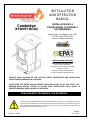
INSTALLATION
AND OPERATION
MANUAL
Cambridge
(EP00075 Model)
INSTALLATION BY A
PROFESSIONAL IS STRONGLY
RECOMMENDED
Safety tested according to ULC S627,
UL1482 and ASTM E1509
by an accredited laboratory.
www.enerzone-intl.com
Stove Builder International Inc.
250, rue de Copenhague,
St-Augustin-de-Desmaures (Quebec)
Canada G3A 2H3
After-sale service: 418-908-8002
E-mail: tech@sbi-international.com
CONTACT LOCAL BUILDING OR FIRE OFFICIALS ABOUT RESTRICTIONS AND INSTALLATION
INSPECTION REQUIREMENTS IN YOUR AREA.
PLEASE READ THIS ENTIRE MANUAL BEFORE INSTALLATION AND USE OF THIS PELLET FUEL-
BURNING ROOM HEATER. FAILURE TO FOLLOW THESE INSTRUCTIONS COULD RESULT IN
PROPERTY DAMAGE, BODILY INJURY OR EVEN DEATH.
READ AND KEEP THIS MANUAL FOR REFERENCE
This manual is available for free download on the manufacturer’s web site. It is a copyrighted document.
Re-sale is strictly prohibited. The manufacturer may update this manual from time to time and cannot
be responsible for problems, injuries, or damages arising out of the use of information contained in any
manual obtained from unauthorized sources.

2 Cambridge Pellet Stove Installation and Operation Manual
THANK YOU FOR CHOOSING THIS ENERZONE PELLET STOVE
As one of North America’s largest and most respected pellet stove, wood stove and fireplace
manufacturers, Stove Builder International takes pride in the quality and performance of all its
products. We want to help you get maximum satisfaction as you use this product.
In the pages that follow you will find general advice on pellet heating, detailed instructions for safe and
effective installation, and guidance on how to get the best performance from this stove as you build
and maintain your pellet heating system.
We highly recommend that our pellet burning hearth products be installed and serviced by
professionals who are certified in the United States by NFI (National Fireplace Institute®) or in Canada
by WETT (Wood Energy Technology Transfer) or in Quebec by APC (Association des Professionnels du
Chauffage).
Congratulations on making a wise purchase.
If this appliance is not properly installed, combustible materials near it may overheat. To reduce the
risk of fire, follow the installation instructions in this manual exactly. Contact local building or fire
officials about restrictions and installation inspection requirements in your area.
Please read this entire manual before you install and use your new stove. You may need to get a building
permit for the installation of this appliance and the venting system that it is connected to. Consult your
municipal building department or fire department before installation. We recommend that you also
inform your home insurance company to find out if the installation will affect your policy.
A primary heat source should be available in the home. This heating unit may serve as a supplementary
heat source. The manufacturer cannot be responsible for additional heating costs associated with the
use of an alternative heat source.
CAUTION
• THE INFORMATION GIVEN ON THE CERTIFICATION LABEL AFFIXED TO THE APPLIANCE ALWAYS
OVERRIDES THE INFORMATION PUBLISHED, IN ANY OTHER MEDIA (OWNER’S MANUAL,
CATALOGUES, FLYERS, MAGAZINES AND/OR WEB SITES).
• MIXING OF APPLIANCE COMPONENTS FROM DIFFERENT SOURCES OR MODIFYING
COMPONENTS IS PROHIBITED AND WILL VOID THE WARRANTY. ANY MODIFICATION OF THE
FIREPLACE THAT HAS NOT BEEN APPROVED IN WRITING BY THE TESTING AUTHORITY IS
PROHIBITED AND VIOLATES CSA B365 (CANADA) AND NFPA 211 (USA).
• STOVE BUILDER INTERNATIONAL INC. (SBI) GRANTS NO WARRANTY, IMPLIED OR STATED, FOR
THE POOR INSTALLATION OR LACK OF MAINTENANCE OF YOUR APPLIANCE AND ASSUMES NO
RESPONSIBILITY OF ANY CONSEQUENTIAL DAMAGES.

Cambridge Pellet Stove Installation and Operation Manual 3
Table of contents
1 CAMBRIDGE GENERAL INFORMATIONS (EP00075)................................................................... 6
1.1 Appliance performance(1) .............................................................................................................. 6
1.2 General Features ........................................................................................................................... 7
1.3 Overall Exterior Dimensions ......................................................................................................... 8
PART A – INSTALLATION ................................................................................................................. 9
2 INSTALLATION SAFETY INFORMATION .................................................................................... 9
2.1 Warnings and Cautions ................................................................................................................. 9
2.2 Regulations Covering Pellet Stove Installation ........................................................................... 11
2.3 Before Operating Your Stove ...................................................................................................... 11
3 CLEARANCES TO COMBUSTIBLE MATERIALS .......................................................................... 12
3.1 Certification Label Location ........................................................................................................ 12
3.2 Clearances to combustibles materials, walls and ceiling ............................................................ 12
3.3 Floor Protection .......................................................................................................................... 14
4 VENTING SYSTEM ................................................................................................................. 15
4.1 General ........................................................................................................................................ 15
4.2 Recommendations ...................................................................................................................... 15
4.3 Equivalent Vent Length (EVL) ...................................................................................................... 15
4.3.1 Recommended Exhaust Venting Diameter ......................................................................... 15
4.3.2 Installation compliance ....................................................................................................... 17
4.4 Termination Location .................................................................................................................. 17
4.4.1 Permitted Termination Location ......................................................................................... 18
4.5 Installation Configurations .......................................................................................................... 19
4.5.1 Installation Warnings, Cautions and Recommendations Reminder ................................... 19
4.5.2 Through Wall Installation (Main Floor or Basement) ......................................................... 20
4.5.3 Through Roof Installation ................................................................................................... 21
4.5.4 Through a Factory Built Chimney ........................................................................................ 22
4.5.5 Through an Existing Masonry Fireplace .............................................................................. 23
4.5.6 Through an Existing Masonry Chimney .............................................................................. 24
PART B - OPERATION .................................................................................................................... 25
5 GENERAL INFORMATION....................................................................................................... 25
5.1 Operation Warnings, Cautions and Recommendations ............................................................. 25
5.1.1 Zone Heating and How to Make It Work for You ................................................................ 27
5.2 Combustible ................................................................................................................................ 28
5.2.1 Proper Fuel .......................................................................................................................... 28
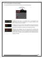
5.2.2 Where to Store Bags of Pellets ............................................................................................ 28
6 STOVE CONTROLS ................................................................................................................. 28
6.1 General Information ................................................................................................................... 28
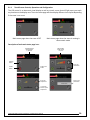
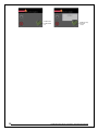
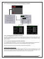
6.1.1 Touch Screen Controls, Operation and Configuration ........................................................ 29
6.1.2 Configuration and Operation Diagram ............................................................................... 31
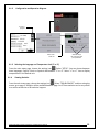
6.1.3 Selecting the Language and Temperature Unit (°F or °C) ................................................... 31
6.1.4 Viewing Statistics ................................................................................................................ 31
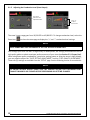
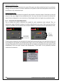
6.1.5 Adjusting the Combustion Level (Heat Output) .................................................................. 32
6.1.6 Combustion Settings and Pilot Settings depending on Fuel Quality ................................... 33
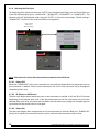
6.1.7 Convection Fan Speed Adjustment...................................................................................... 34
6.1.8 Selecting Manual or Thermostatic Mode ............................................................................ 35

4 Cambridge Pellet Stove Installation and Operation Manual
6.1.9 Selecting the Pilot Cycle ...................................................................................................... 36
6.1.10 Purging the pellet feeding systems ..................................................................................... 37
6.1.11 Demo Mode ......................................................................................................................... 38
7 STOVE OPERATION ............................................................................................................... 39
7.1 First Startup ................................................................................................................................. 39
7.2 Everyday Startup ......................................................................................................................... 39
7.3 Running Out of Pellets ................................................................................................................ 39
7.4 Refueling ..................................................................................................................................... 40
7.5 Shutting Down Procedure ........................................................................................................... 40
7.6 Signs of an Overheating Stove .................................................................................................... 40
8 MAINTENANCE ..................................................................................................................... 41
8.1 Stove Maintenance ..................................................................................................................... 41
8.1.1 Recommended Maintenance Schedule ............................................................................... 41
8.1.2 Cleaning the Baffle and the Combustion Chamber. ............................................................ 42
8.1.3 Exhaust Channel and Exhaust Blower Maintenance ........................................................... 44
8.1.4 Cleaning the Burn Pot ......................................................................................................... 47
8.1.5 Ash Removal ........................................................................................................................ 48
8.1.6 Cleaning the Air Wash System ............................................................................................ 49
8.1.7 Glass Care ............................................................................................................................ 50
8.1.8 Replacement of Broken Door Glass ..................................................................................... 50
8.1.9 Door Gasket Maintenance .................................................................................................. 50
8.1.10 Door Adjustment ................................................................................................................. 51
8.2 Venting System Maintenance ..................................................................................................... 51
8.2.1 Dealing With a Chimney Fire ............................................................................................... 52
8.2.2 Soot and Fly Ash .................................................................................................................. 52
9 TROUBLESHOOTING .............................................................................................................. 53
9.1 Validating Status ......................................................................................................................... 53
9.2 Testing Components ................................................................................................................... 55
9.3 Main Error Codes, Possible Causes and Solutions ...................................................................... 55
9.3.1 Blocked Flue ........................................................................................................................ 56
9.3.2 No Fuel ................................................................................................................................ 57
9.3.3 Failed Ignition ...................................................................................................................... 59
9.3.4 Defective Igniter Fuse .......................................................................................................... 60
9.3.5 Auger Fuse ........................................................................................................................... 60
9.3.6 Unit Overheat ...................................................................................................................... 61
9.3.7 Hopper Lid Open .................................................................................................................. 62
9.3.8 Power Loss ........................................................................................................................... 63
9.3.9 Smoke Smell ........................................................................................................................ 63
9.3.10 Combustion Air Starvation .................................................................................................. 64
9.3.11 The LCD Touch Screen Does Not Lightup. ........................................................................... 64
10 WIRING DIAGRAM ................................................................................................................ 65
11 ACCESS TO FUSES .................................................................................................................. 66
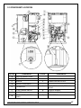
12 COMPONENTS LOCATION ..................................................................................................... 67
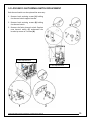
13 BLOWER REPLACEMENT ........................................................................................................ 69
13.1 Convection blower ...................................................................................................................... 69
13.2 Combustion blower ..................................................................................................................... 70
13.3 Exhaust blower ............................................................................................................................ 71

Cambridge Pellet Stove Installation and Operation Manual 5
14 L-250 AND F-160 THERMAL SWITCH REPLACEMENT ............................................................... 73
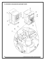
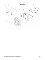
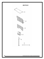
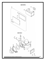
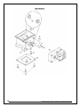
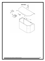
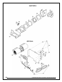
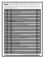
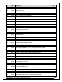
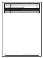
15 EXPLODED VIEW AND REPLACEMENT PARTS ......................................................................... 74
APPENDIX A: HORIZONTAL AND VERTICAL VENT CHART ............................................................... 85
APPENDIX B: CONNECTING AND INSTALLING THE TOUCHSCREEN ................................................. 87
APPENDIX C: INSTALLING A THERMOSTAT (AC05558) ................................................................... 88
APPENDIX D: MOBILE HOME INSTALLATION ................................................................................. 90
APPENDIX E: COMBUSTION AIR SUPPLY ....................................................................................... 92
ENERZONE LIMITED LIFETIME WARRANTY .................................................................................... 94
REGISTER YOUR WARRANTY ONLINE
To receive full warranty coverage, you will need to show evidence of the date you purchased your
stove. Keep your sales invoice. We also recommend that you register your warranty online at:
http://enerzone-intl.com/warranty-registration.aspx
Registering your warranty online will help us to quickly track the information we need about your
stove.

6 Cambridge Pellet Stove Installation and Operation Manual
1 CAMBRIDGE GENERAL INFORMATIONS (EP00075)
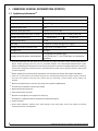
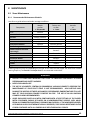
1.1 Appliance performance(1)
Fuel type
Wood Pellet (Premium grade or better)(☨)
Recommended heating area[*]
500 to 2,200 ft2 (46 to 185 m2)
Hopper capacity
60 lb (27 kg)
Maximum burn time[*]
50 h
Maximum heat input rate(2)
43,000 BTU/h (12.6 kW)
Overall heat output rate (min. to max.)(3)
6,400 BTU/h to 29,300 BTU/h (1.9 kW to 8.6 kW)
Average overall efficiency(3)
69.8% (HHV(4))
75.3% (LHV(5))
Optimum efficiency(6)
77.2%
Burn rate
1.2 lb/h to 5.0 lb/h (0.5 kg/h to 2.3 kg/h)
Average particulate emissions rate(7)
2.9 g/h (EPA / CSA B415.1-10)
Average CO(8)
41.2 g/h
Average electrical power consumption(9)
3.5A (420W) for ignition cycle
2.3A (276W) min. / 3.1A (372W) max. for continuous
operation
[*] Recommended heating area and maximum burn time may vary subject to location in home, chimney draft, heat loss
factors, climate, fuel type, feed rate, fuel level, and other variables. The recommended heated area for a given
appliance is defined by the manufacturer as its capacity to maintain a minimum acceptable temperature considering
that the space configuration and the presence of heat distribution systems have a significant impact in making heat
circulation optimum.
(
☨
) Grades of pellet fuel are determined by organizations such as Pellet Fuels Institute (PFI), ENplus and CANplus.
(1) Values are as measured per test method, except for the recommended heating area, hopper capacity, maximum
burn time and maximum heat input rate. Results may vary depending on pellet quality, density, length, and
diameter.
(2) Based on the maximum burn-rate and a dry energy value of pellet at 8,600 BTU/lb.
(3) As measured per CSA B415.1-10 stack loss method.
(4) Higher Heating Value of the fuel.
(5) Lower Heating Value of the fuel.
(6) Optimum overall efficiency at a specific burn rate (LHV).
(7) This appliance is officially tested and certified by an independent agency.
(8) Carbon monoxide.
(9) Unless stated otherwise, measures were taken directly at the main power source and include all electrical
components present in the appliance.

Cambridge Pellet Stove Installation and Operation Manual 7
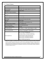
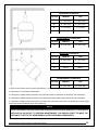
1.2 General Features
Recommended chimney diameter
3 po
Flue outlet diameter
3 po (75 mm)
Type of chimney
ULC/ORD-C441, CAN/ULC S609, UL 641 (TYPE L)
Baffle material
Stainless Steel
Approved for alcove installation
Yes
Approved for mobile home
installation‡
Yes
Shipping weight (without option)
348 lb (158 kg)
Appliance weight (without option)
294 lb (133 kg)
Type of door
Single, glass with cast iron frame
Glass type
Ceramic glass
Blower
Included (up to 176 CFM (0.08 m3/s))
Particulate emission standard
EPA / CSA B415.1-10
USA standard (safety)
ASTM E1509 and UL 1482
Canadian standard (safety)
ULC S627
Noise level at 6 feet
Min: 49 dBa (+/- 3 dBa) − Max: 59 dBa (+/- 3 dBa)
Electrical requirements
Voltage and frequency: 120VAC and 60Hz
AC Current: 2.3A/120VAC - 3.5A/120VAC
Control board fuses
Main: 7.5A-250V fast-blow fuse
Convection blower: 5A-250V fast-blow fuse
Combustion blower: 3A-250V fast-blow fuse
Exhaust blower: 3A-250V fast-blow fuse
Auger motor #1: 3A-250V fast-blow fuse
Auger motor #2: 3A-250V fast-blow fuse
Igniter: 5A-250V fast-blow fuse
‡ Mobile home (Canada) or manufactured home (USA): The US department of Housing and Urban Development
describes “manufactured homes” better known as “mobile homes” as followed; buildings built on fixed wheels and
those transported on temporary wheels/axles and set on a permanent foundation. In Canada, a mobile home is a
dwelling for which the manufacture and assembly of each component is completed or substantially completed prior
to being moved to a site for installation on a foundation and connection to service facilities and which conforms to
the CAN/CSA-Z240 MH standard.

8 Cambridge Pellet Stove Installation and Operation Manual
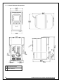
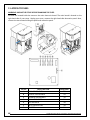
1.3 Overall Exterior Dimensions
A
FRESH AIR INTAKE
B
FLUE OUTLET

Cambridge Pellet Stove Installation and Operation Manual 9
PART A – INSTALLATION
2 INSTALLATION SAFETY INFORMATION
2.1 Warnings and Cautions
ATTENTION
THE INFORMATION GIVEN ON THE CERTIFICATION LABEL AFFIXED TO THE STOVE ALWAYS
OVERRIDES THE INFORMATION PUBLISHED IN ANY OTHER MEDIA (OWNER’S MANUAL,
CATALOGUES, FLYERS, MAGAZINES AND/OR WEB SITES).
CAUTION
• IF THIS STOVE IS NOT PROPERLY INSTALLED, A HOUSE FIRE MAY RESULT. TO REDUCE THE RISK
OF FIRE, FOLLOW THE INSTALLATION INSTRUCTIONS.
• BURNING ANY SOLID FUELS GENERATES CARBON MONOXIDE IN LOW CONCENTRATION. THIS
GAS IS EVACUATED BY THE EXHAUST VENTING SYSTEM. IN HIGHER CONCENTRATIONS,
CARBON MONOXIDE IS TOXIC AND MAY CAUSE DEATH. TO PREVENT THIS, ENSURE THAT
YOUR EXHAUST VENTING SYSTEM IS AIRTIGHT.
WARNING – APPLIANCE LOCATION
• WHEN LOCATING YOUR APPLIANCE, MAKE SURE THE VENT WILL NOT INTERFERE WITH ANY
TRUSS, ROOF BEAMS, WALL STUDS, WATER PIPES OR ELECTRICAL WIRING. IT MAY BE EASIER
TO RELOCATE APPLIANCE THAN TO REWORK THE BUILDING STRUCTURE.
• THIS STOVE IS NOT RECOMMENDED TO BE INSTALLED IN A BEDROOM.
WARNING – VENTING SYSTEM
• CONNECT THIS STOVE ONLY TO A LISTED PELLET EXHAUST VENTING SYSTEM FOR USE WITH
SOLID FUEL OR TO A LINED CHIMNEY CONFORMING TO NATIONAL AND LOCAL BUILDING
CODES.
• DO NOT INSTALL A FLUE DAMPER IN THE EXHAUST VENTING SYSTEM OF THIS UNIT.
• DO NOT CONNECT THIS STOVE TO ANY OTHER EXISTING VENTING SYSTEM SERVING ANOTHER
APPLIANCE.
• DO NOT CONNECT TO OR USE IN CONJUNCTION WITH ANY AIR DISTRIBUTION DUCTWORK.
• THE VENTING SYSTEM MUST BE COMPLETELY AIRTIGHT AND PROPERLY INSTALLED. ALL VENT
CONNECTOR JOINTS MUST BE SEALED AND FASTENED IN ACCORDANCE WITH THE PELLET
VENT MANUFACTURER'S INSTRUCTIONS TO ENSURE CONSISTENT PERFORMANCE AND AVOID
SMOKE AND ASH SPILLAGE.
• THE VENTING SYSTEM SHOULD BE CHECKED, AT LEAST TWICE A YEAR FOR ANY BUILDUP OF
SOOT OR CREOSOTE.

10 Cambridge Pellet Stove Installation and Operation Manual
WARNING – APPLIANCE INSTALLATION
• PROFESSIONNAL INSTALLATION IS HIGHLY RECOMMENDED.
• YOU MAY NEED TO OBTAIN A BUILDING PERMIT FOR THE INSTALLATION OF THIS STOVE AND
ITS VENTING SYSTEM. CONSULT YOUR MUNICIPAL BUILDING DEPARTMENT OR FIRE
DEPARTMENT BEFORE INSTALLATION TO DETERMINE THE NEED TO OBTAIN ONE. WE
RECOMMEND THAT YOU ALSO INFORM YOUR HOME INSURANCE COMPANY TO FIND OUT IF
THE INSTALLATION WILL AFFECT YOUR POLICY.
• THIS STOVE MUST BE CONNECTED TO A STANDARD 120V. 60 HZ GROUNDED ELECTRICAL
OUTLET. DO NOT USE AN ADAPTER PLUG OR SEVER THE GROUNDING PLUG. DO NOT ROUTE
THE ELECTRICAL CORD UNDERNEATH, IN FRONT OR OVER THE STOVE.
• THIS STOVE IS MOBILE HOME APPROVED AND REQUIRES INSTALLATION OF A FRESH AIR KIT,
SOLD SEPARATELY. THE STOVE MUST BE ATTACHED TO THE STRUCTURE OF THE MOBILE HOME
AND THE STRUCTURAL INTEGRITY OF THE MOBILE HOME FLOOR, WALL, AND CEILING/ROOF
MUST BE MAINTAINED. DO NOT INSTALL IN A SLEEPING ROOM.
• IF REQUIRED, A FRESH AIR KIT CAN BE INSTALLED TO SUPPLY COMBUSTION AIR TO THE ROOM
OR SPACE (SEE APPENDIX E: COMBUSTION AIR SUPPLY).
• STOVE BUILDER INTERNATIONAL INC. (SBI) GRANTS NO WARRANTY, IMPLIED OR STATED, FOR
THE POOR INSTALLATION OR LACK OF MAINTENANCE OF YOUR STOVE AND ASSUMES NO
RESPONSIBILITY OF ANY CONSEQUENTIAL DAMAGES.
WARNING – APPLIANCE OPERATION AND MAINTENANCE
• THIS STOVE HAS BEEN DEVELOPED AND BUILT FOR RESIDENTIAL SUPPLEMENTARY HEAT
SOURCE. COMMERCIAL AND INDUSTRIAL USE IS PROHIBITED AND WILL VOID THE WARRANTY.
• NEVER BLOCK ANY LOUVERS OF THE STOVE.
• MIXING OF APPLIANCE COMPONENTS FROM DIFFERENT SOURCES OR MODIFYING
COMPONENTS IS PROHIBITED AND WILL VOID THE WARRANTY.
• ANY MODIFICATION OF THE STOVE THAT HAS NOT BEEN APPROVED IN WRITING BY THE
TESTING AUTHORITY IS PROHIBITED AND VIOLATES CSA B365 (CANADA), AND ANSI NFPA 211
(USA).

Cambridge Pellet Stove Installation and Operation Manual 11
2.2 Regulations Covering Pellet Stove Installation
When installed and operated as described in these instructions, this pellet stove is suitable for use as a
freestanding heater in residential installations.
In Canada, the CSA B365 Installation Code for Solid Fuel Burning Appliances and Equipment and the CSA
C22.1 Canadian National Electrical Code are to be followed in the absence of local code requirements.
In the USA, the ANSI NFPA 211 Standard for Chimneys, Fireplaces, Vents and Solid Fuel-Burning
Appliances and the ANSI NFPA 70 National Electrical Code are to be followed in the absence of local
code requirements.
This stove must be connected to a pellet vent system complying with the requirements for Pellet Vent
in the standards UL 103, UL 641, ULC S629M, CAN/ULC S609 and ULC/ORD C441 or to a code-approved
masonry chimney with a stainless steel flue liner.
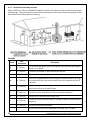
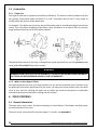
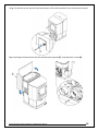
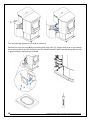
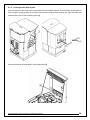
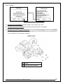
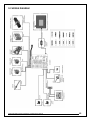
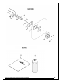
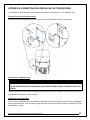
2.3 Before Operating Your Stove
Some minor installation and adjustment are required prior to use:
• LCD support can be installed at the back of the stove, on the right or the left; (see Appendix B)
• The handle and door must be adjusted; (see section 8.1.10 Door Adjustment)
• The stove must be leveled using threaded legs;
• Make sure the back draft shutter (F) from the fresh air intake works freely.
• Make sure to remove all tools or accessories that have been inserted in the stove for transportation
purposes (see following illustration.)
A
Installation and Operation manual
B
Touch Screen
C
Touch Screen support
D
Power cord
E
Dessicant (moisture absorbant)

12 Cambridge Pellet Stove Installation and Operation Manual
3 CLEARANCES TO COMBUSTIBLE MATERIALS
The clearances shown in this section have been determined by tests according to procedures set out in
safety standards ULC S627 (Canada), ASTM E1509 (U.S.A) and UL1482 (USA). When the pellet stove is
installed so that its surfaces are at, or beyond, the minimum clearances specified, combustible surfaces
will not overheat under normal and even abnormal operating conditions.
WARNING
• NO PART OF THE STOVE MAY BE LOCATED CLOSER TO COMBUSTIBLES THAN THE MINIMUM
CLEARANCES SPECIFIED ON THE CERTIFICATION LABEL.
• NO PART OF THE PELLET VENT SYSTEM MAY BE LOCATED CLOSER TO COMBUSTIBLES THAN
THE MINIMUM CLEARANCES SPECIFIED BY THE VENT MANUFACTURER.
CAUTION
• DO NOT USE MAKESHIFT MATERIALS OR MAKE ANY COMPROMISES WHEN INSTALLING THIS
STOVE.
3.1 Certification Label Location
Since the information given on the certification label affixed to the stove always overrides the
information published in any other media (owner’s manual, catalogues, flyers, magazines and/or web
sites), it is important to refer to it in order to have a safe and compliant installation. In addition, you
will find important information about your stove (model, serial number, etc.). You will find the
certification label on the inner side of the hopper lid of the stove.
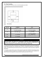
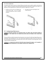
3.2 Clearances to combustibles materials, walls and ceiling
The distances listed in this table refer to the distances obtained during regular testing. However, it is
possible to install the stove at reduced clearances by installing either a certified heat shield system
(AC02710) or a side clearance reduction kit (AC02733), sold separately.
* From the rear panel
**Measured from the platform on which the
product is installed.
RECOMMENDED CLEARANCES2
LETTER
CANADA
USA
A*
12" (305 mm)
12" (305 mm)
MINIMUM CLEARANCES
LETTER
CANADA
USA
A*
3" (76 mm)
3" (76 mm)
D
Note 1
Note 1
I**
48" (1 220 mm)
48" (1 220 mm)

Cambridge Pellet Stove Installation and Operation Manual 13
RECOMMENDED CLEARANCES2
LETTER
CANADA
USA
B
24" (610 mm)
24" (610 mm)
MINIMUM CLEARANCES
LETTER
CANADA
USA
B
17" (432 mm)
17" (432 mm)
B3
8" (203 mm)
8" (203 mm)
B4
3" (76 mm)
3" (76 mm)
D
Note 1
Note 1
RECOMMENDED CLEARANCES2
LETTER
CANADA
USA
C
12" (305 mm)
12" (305 mm)
MINIMUM CLEARANCES
LETTER
CANADA
USA
C
4" (102 mm)
4" (102 mm)
C5
3" (76 mm)
3" (76 mm)
D
Note 1
Note 1
1: Refer to the exhaust venting system manufacturer’s instructions for clearances to combustible materials.
2: Clearances are to facilitate maintenance.
3: Clearances to adjacent wall reduced by using the side clearance reduction kit (AC02733), sold separately.
4: Clearances to adjacent wall reduced by using the certified heat shield system (AC02710), sold separately.
5: Clearances to adjacent wall reduced by using either the side clearance reduction kit (AC02733) or the certified
heat shield system (AC02710), both sold separately.
NOTE
THESE CLEARANCES ARE ALSO VALID FOR AN ALCOVE INSTALLATION. HOWEVER, IF THE STOVE IS
INSTALLED IN AN ALCOVE, TO PERFORM MAINTENANCE, YOU SHOULD EXPECT TO MOVE THE
APPLIANCE TO GET TO THE MAINTENANCE ACCESS DOORS AND COMPONENTS.

14 Cambridge Pellet Stove Installation and Operation Manual
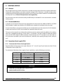
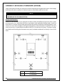
3.3 Floor Protection
For floor protection clearances refer to the following figure and table.
LETTER
CANADA
USA
E
18" (460 mm)**
From door opening
6" (155 mm)
From door opening
F
N/A (USA only)
6" (155 mm)
From door opening
G
8" (205 mm)
N/A (Canada only)
H
8" (205 mm)
N/A (Canada only)
CAUTION
THE STOVE MUST BE PLACED ON A CONTINUOUS (GROUTED JOINTS) NONCOMBUSTIBLE
MATERIAL SUCH AS CERAMIC TILE*, CEMENT BOARD, BRICK, MILLBOARD OR EQUIVALENT, OR
ANY OTHER APPROVED OR LISTED MATERIAL SUITED FOR FLOOR PROTECTION.
*Any type of tile will require a continuous non combustible sheet beneath to prevent the possibility of
embers falling through to the combustible floor if cracks or separation should occur in the finished
surface, this would include floor protection for built-in raised hearths. Check local codes for approved
alternatives.
**In Canada, you may reduce to the U.S. floor protection requirements (E) ONLY if the following actions
are respected: Allow for the appliance to shut-down and fires to be extinguish. Once completely cool
and all blowers have stopped you may proceed with opening the firebox or ash door.

Cambridge Pellet Stove Installation and Operation Manual 15
4 VENTING SYSTEM
4.1 General
Even though the chimney draft is mechanical, a suitable venting system will ensure a natural draft which
will prevent smoke spillage in your home if a power outage occurs. Moreover, a suitable venting system
configuration will help getting the best efficiency out of your stove when installed in accordance with
the required EVL (see Section 4.3 Equivalent Vent Length (EVL)).
Even the best stove will not function safely and efficiently as intended if it is not connected to a suitable
venting system.
4.2 Recommendations
In Canada, we recommend that you use a listed pellet vent that meets the CAN/ULC S609 or ULC/ORD
C441 Standard. A pellet vent listed to ULC S629M is also suitable for installation with this stove.
For the United States, we recommend that you use a listed pellet vent that meets the UL 641 Standard.
A pellet vent listed to UL 103 is also suitable for installation with this stove.
This stove can be vented in an existing factory-built or masonry chimney with the addition of a stainless
steel liner, provided the chimney is more than 4” in diameter. The liner should be listed and should
meet the ULC S635 CAN/ULC S640 standard in Canada and the UL 1777 standard in the USA. Refer to
the instructions provided by the vent manufacturer, especially when passing through a wall, ceiling or
roof.
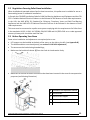
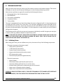
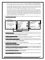
4.3 Equivalent Vent Length (EVL)
4.3.1 Recommended Exhaust Venting Diameter
Recommended venting system inner pipe diameter is 3”. Use a 4” pipe if you have more than 15 feet
of Equivalent Vent Length (EVL).
To calculate the Equivalent Vent Length of your installation, use the following conversions:
Qty
Type of pipe
Equivalent Length (EVL)
1
90° elbow or “T”
5 feet
1
45° elbow
3 feet
1 foot
Horizontal pipe run
1 foot
1 foot
Vertical pipe run
0.5 foot
CAUTION
• HORIZONTAL RUNS SHALL NOT EXCEED 9 FEET.
• NEVER EXCEED 30 FEET OF EVL.

16 Cambridge Pellet Stove Installation and Operation Manual
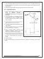
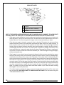
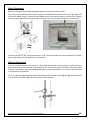
Here is an example to help you calculate Equivalent Vent Length. On the following figure the EVL can
be calculated like this:
• 2 horizontal run of 1’ = (2 X 1’) X 1’ = 2’ of EVL
• 1 elbow 90° or "Tee" = 5’ of EVL
• 3 vertical length of 4’ = (3 X 4’) X 0.5’ = 6’ of EVL
• Total EVL = (2’ + 5’ + 6’) = 13’
Since the total EVL is less than 15 feet, the recommended exhaust venting diameter is 3".
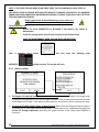
NOTE
DO NOT INCLUDE THE EXTERIOR WALL TERMINATION IN THE
EVL CALCULATION (45° ELBOW AND TERMINATION COLLAR).

Cambridge Pellet Stove Installation and Operation Manual 17
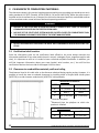
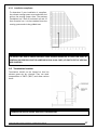
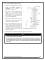
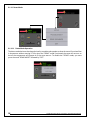
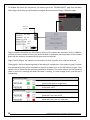
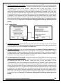
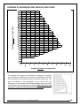
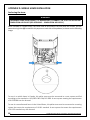
4.3.2 Installation compliance
To determine if your installation is compliant,
the exhaust venting system must end within the
grid on the venting system chart. The previous
installation has 2 feet of horizontal run and 12
feet of vertical run. It is thus standard since the
venting system ends in the gridded area.
WARNING
TO REDUCE THE RISK OF SMOKE SPILLAGE THERE SHOULD ALWAYS BE AT LEAST ONE FOOT OF
VERTICAL RISE FOR EACH FOOT OF HORIZONTAL RUN. IN ALL CASES, AT LEAST 3 FEET OF VERTICAL
RISE IS NEEDED.
4.4 Termination Location
Termination should not be located so that hot
exhaust gases can be a hazard. They can reach
temperatures of 500°F (260°C) and cause serious
burns.
CAUTION
TERMINATION COLLAR (SPARK ARRESTER) IS MANDATORY.

18 Cambridge Pellet Stove Installation and Operation Manual
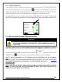
4.4.1 Permitted Termination Location
Refer to NFPA 211 (USA) or CSA B365 (Canada) for rules for the distance of exit terminal from windows
and openings. The exit terminal of a mechanical draft system, other than a direct vent appliance shall
be located in accordance with the following.
Canada:
Letter
Min.
clearances
Description
A
12" (30 cm)
Clearances above grade level or any adjacent surface that might support
snow, ice, or debris.
B
39" (100 cm)
Clearance to window or door that may be opened.
F
39" (100 cm)
Clearance to corner or adjacent wall.
H
39" (100 cm)
Not to be installed above a meter/regulator assembly within 39" (100
cm) horizontally from the vertical center-line of the regulator and for 15’
vertically.
I
72" (183 cm)
Clearance to gas service regulator vent outlet or within 39’’ (100 cm) of
an oil tank vent or an oil tank fill inlet.
J
39" (100 cm)
Clearance to the combustion air inlet to any other appliance.
K
72" (183 cm)
Clearance to a mechanical air supply inlet.
L
84" (213 cm)
Clearance above paved side-walk or a paved driveway located on public
property.
39" (100 cm)
Clearance to property boundary.
A vent shall not terminate underneath a veranda, porch, or deck.

Cambridge Pellet Stove Installation and Operation Manual 19
United States:
• Not Less than 36" (91 cm) above any forced air inlet located within 120" (305 cm);
• Not Less than 48" (122 cm) below and horizontally from, or 12" (30 cm) above, any door, window
or gravity air inlet into any building;
• Not Less than 24" (61 cm) from an adjacent building and not less than 84" (213 cm) above grade
when located adjacent to a public walkway;
• Cannot be located less than 12" (30 cm) above grade;
• Cannot be located above a gas meter/regulator within 36" (91cm) horizontally of the vertical center
line of the regulator;
• Not within 6 feet (183 cm) of a gas service regulator vent outlet;
• Other restrictions may apply. See NFPA 211 for further information.
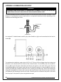
4.4.1.1 Direct Vent System (2-in-1 Exhaust and fresh air intake)
In Canada: The permitted termination location for a direct vent system are the same than those
permitted with a regular pellet vent system.
In the Unites States: The permitted termination location for a direct vent system are the same than
those permitted with a regular pellet vent system except for the following : The exit terminal shall be
located not less than 9" (23 cm) from any opening through which vent gases could enter a building.
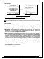
4.5 Installation Configurations
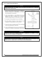
4.5.1 Installation Warnings, Cautions and Recommendations Reminder
CAUTION
• PROFESSIONNAL INSTALLATION IS HIGHLY RECOMMENDED.
• THIS STOVE USES A PRESSURIZED VENTING SYSTEM. ALL VENT CONNECTOR JOINTS MUST BE
SEALED AND FASTENED. YOU MAY USE RTV SILICONE (ROOM TEMPERATURE
VULCANISATION), METALLIC TAPE, AND A MINIMUM OF THREE SELF-TAPING SCREWS AT ALL
JOINT CONNECTIONS TO ENSURE A TIGHT SEAL. CONSULT THE PELLET VENT
MANUFACTURER’S INSTRUCTION TO ENSURE PROPER INSTALLATION, CONSISTENT
PERFORMANCE, AND TO AVOID SMOKE AND ASH SPILLAGE.
• THE CHIMNEY CONNECTOR SHALL NOT PASS THROUGH AN ATTIC OR ROOF SPACE, CLOSET OR
SIMILAR CONCEALED SPACE OR FLOORS OR CEILING.
• INSTALL VENTING SYSTEM AT CLEARANCES SPECIFIED BY THE VENT MANUFACTURER.
• THE USE OF A SPARK ARRESTER AT THE END OF THE TERMINATION IS MANDATORY. IT IS
IMPORTANT THAT THE SPARK ARRESTER BE CLEAR OF ANY DEBRIS AT ALL TIME.

20 Cambridge Pellet Stove Installation and Operation Manual
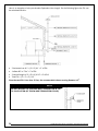
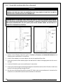
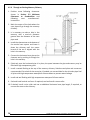
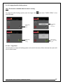
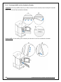
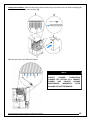
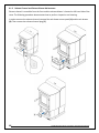
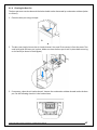
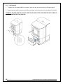
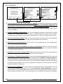
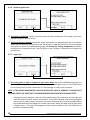
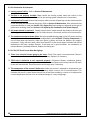
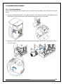
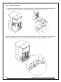
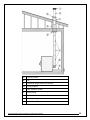
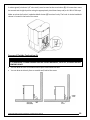
4.5.2 Through Wall Installation (Main Floor or Basement)
CAUTION
TO REDUCE THE RISK OF SMOKE SPILLAGE THERE SHOULD ALWAYS BE AT LEAST 12" (30 CM) OF
VERTICAL RISE FOR EACH FOOT OF HORIZONTAL RUN. IN ALL CASES, AT LEAST 36" (91 CM) OF
VERTICAL RISE IS NEEDED BEFORE THE TERMINATION.
1. Position stove following clearances given in Section 3, Clearances to Combustible Material and
following vent manufacturer’s instructions.
2. Install a stove adapter or a stove adapter tee onto the appliance flue collar.
3. Locate the position of the exhaust pipe in the wall and cut a hole of the appropriate size for vent in
the wall.
4. Install wall thimble as per vent manufacturer’s instructions.
5. Ensure you install enough horizontal pipe length to exceed the exterior wall of 6 inches. Install a tee
section to the pipe passing through the wall.
6. Run the vent vertically up the wall for at least 36". Refer to the vent manufacturer’s instructions for
clearances to combustible materials and installation of wall bands.
WARNING
TERMINATION OF A SIDE WALL VENT SHOULD BE LOCATED TO AVOID PERSONAL BURN INJURY,
FIRE HAZARD AND INTERFERENCE WITH OR DAMAGE TO ADJACENT PROPERTIES. EXHAUST GASES
CAN REACH TEMPERATURES OF 500°F (260°C) AND CAUSE SERIOUS BURNS. SEE SECTION 4.4.1
PERMITTED TERMINATION LOCATION.
Page is loading ...
Page is loading ...
Page is loading ...
Page is loading ...
Page is loading ...
Page is loading ...
Page is loading ...
Page is loading ...
Page is loading ...
Page is loading ...
Page is loading ...
Page is loading ...
Page is loading ...
Page is loading ...
Page is loading ...
Page is loading ...
Page is loading ...
Page is loading ...
Page is loading ...
Page is loading ...
Page is loading ...
Page is loading ...
Page is loading ...
Page is loading ...
Page is loading ...
Page is loading ...
Page is loading ...
Page is loading ...
Page is loading ...
Page is loading ...
Page is loading ...
Page is loading ...
Page is loading ...
Page is loading ...
Page is loading ...
Page is loading ...
Page is loading ...
Page is loading ...
Page is loading ...
Page is loading ...
Page is loading ...
Page is loading ...
Page is loading ...
Page is loading ...
Page is loading ...
Page is loading ...
Page is loading ...
Page is loading ...
Page is loading ...
Page is loading ...
Page is loading ...
Page is loading ...
Page is loading ...
Page is loading ...
Page is loading ...
Page is loading ...
Page is loading ...
Page is loading ...
Page is loading ...
Page is loading ...
Page is loading ...
Page is loading ...
Page is loading ...
Page is loading ...
Page is loading ...
Page is loading ...
Page is loading ...
Page is loading ...
Page is loading ...
Page is loading ...
Page is loading ...
Page is loading ...
Page is loading ...
Page is loading ...
-
 1
1
-
 2
2
-
 3
3
-
 4
4
-
 5
5
-
 6
6
-
 7
7
-
 8
8
-
 9
9
-
 10
10
-
 11
11
-
 12
12
-
 13
13
-
 14
14
-
 15
15
-
 16
16
-
 17
17
-
 18
18
-
 19
19
-
 20
20
-
 21
21
-
 22
22
-
 23
23
-
 24
24
-
 25
25
-
 26
26
-
 27
27
-
 28
28
-
 29
29
-
 30
30
-
 31
31
-
 32
32
-
 33
33
-
 34
34
-
 35
35
-
 36
36
-
 37
37
-
 38
38
-
 39
39
-
 40
40
-
 41
41
-
 42
42
-
 43
43
-
 44
44
-
 45
45
-
 46
46
-
 47
47
-
 48
48
-
 49
49
-
 50
50
-
 51
51
-
 52
52
-
 53
53
-
 54
54
-
 55
55
-
 56
56
-
 57
57
-
 58
58
-
 59
59
-
 60
60
-
 61
61
-
 62
62
-
 63
63
-
 64
64
-
 65
65
-
 66
66
-
 67
67
-
 68
68
-
 69
69
-
 70
70
-
 71
71
-
 72
72
-
 73
73
-
 74
74
-
 75
75
-
 76
76
-
 77
77
-
 78
78
-
 79
79
-
 80
80
-
 81
81
-
 82
82
-
 83
83
-
 84
84
-
 85
85
-
 86
86
-
 87
87
-
 88
88
-
 89
89
-
 90
90
-
 91
91
-
 92
92
-
 93
93
-
 94
94


Ask a question and I''ll find the answer in the document
Finding information in a document is now easier with AI
Related papers
Other documents
-
Osburn OP00025 Installation guide
-
Drolet ECO-55 PELLET STOVE Installation guide
-
-
 Drolet ECO-65 PELLET STOVE Owner's manual
-
 Drolet EDISON PELLET STOVE User manual
-
-
 Drolet ECO-45 PELLET STOVE User manual
-
-
-
 Drolet ECO-65 PELLET STOVE User manual


