Page is loading ...

53-1002580-01
9 May 2012
®
Brocade 6910 Ethernet Access Switch
Hardware Installation Guide

Copyright © 2012 Brocade Communications Systems, Inc. All Rights Reserved.
Brocade, the B-wing symbol, BigIron, DCX, Fabric OS, FastIron, NetIron, SAN Health, ServerIron, and TurboIron are registered
trademarks, and Brocade Assurance, Brocade NET Health, Brocade One, CloudPlex, MLX, VCS, VDX, and When the Mission Is
Critical, the Network Is Brocade are trademarks of Brocade Communications Systems, Inc., in the United States and/or in other
countries. Other brands, products, or service names mentioned are or may be trademarks or service marks of their respective
owners.
Notice: This document is for informational purposes only and does not set forth any warranty, expressed or implied, concerning
any equipment, equipment feature, or service offered or to be offered by Brocade. Brocade reserves the right to make changes to
this document at any time, without notice, and assumes no responsibility for its use. This informational document describes
features that may not be currently available. Contact a Brocade sales office for information on feature and product availability.
Export of technical data contained in this document may require an export license from the United States government.The
authors and Brocade Communications Systems, Inc. shall have no liability or responsibility to any person or entity with respect to
any loss, cost, liability, or damages arising from the information contained in this book or the computer programs that accompany
it.
The product described by this document may contain “open source” software covered by the GNU General Public License or other
open source license agreements. To find out which open source software is included in Brocade products, view the licensing
terms applicable to the open source software, and obtain a copy of the programming source code, please visit
http://www.brocade.com/support/oscd.
Brocade Communications Systems, Incorporated
Document History
Corporate and Latin American Headquarters
Brocade Communications Systems, Inc.
130 Holger Way
San Jose, CA 95134
Tel: 1-408-333-8000
Fax: 1-408-333-8101
E-mail: info@brocade.com
Asia-Pacific Headquarters
Brocade Communications Systems China HK, Ltd.
No. 1 Guanghua Road
Chao Yang District
Units 2718 and 2818
Beijing 100020, China
Tel: +8610 6588 8888
Fax: +8610 6588 9999
E-mail: china-info@brocade.com
European Headquarters
Brocade Communications Switzerland Sàrl
Centre Swissair
Tour B - 4ème étage
29, Route de l'Aéroport
Case Postale 105
CH-1215 Genève 15
Switzerland
Tel: +41 22 799 5640
Fax: +41 22 799 5641
E-mail: emea-info@brocade.com
Asia-Pacific Headquarters
Brocade Communications Systems Co., Ltd. (Shenzhen WFOE)
Citic Plaza
No. 233 Tian He Road North
Unit 1308 – 13th Floor
Guangzhou, China
Tel: +8620 3891 2000
Fax: +8620 3891 2111
E-mail: china-info@brocade.com
Title Publication number Summary of changes Date
Brocade 6910 Ethernet Access Switch
Hardware Installation Guide
53-1002345-01 New document December 2011
Brocade 6910 Ethernet Access Switch
Hardware Installation Guide
53-1002345-02 Updated package contents January 2012
Brocade 6910 Ethernet Access Switch
Hardware Installation Guide
53-1002345-03 Updated Cautions and
Dangers appendices
February 2012
Brocade 6910 Ethernet Access Switch
Hardware Installation Guide
53-1002580-01 Updated formating May 2012

Brocade 6910 Ethernet Access Switch Hardware Installation Guide iii
53-1002580-01
Contents
About This Document
Audience . . . . . . . . . . . . . . . . . . . . . . . . . . . . . . . . . . . . . . . . . . . . . . . . xi
Supported hardware and software . . . . . . . . . . . . . . . . . . . . . . . . . . . xi
Document conventions. . . . . . . . . . . . . . . . . . . . . . . . . . . . . . . . . . . . . xi
Text formatting . . . . . . . . . . . . . . . . . . . . . . . . . . . . . . . . . . . . . . . .xi
Notes, cautions, and danger notices . . . . . . . . . . . . . . . . . . . . . xii
Related publications . . . . . . . . . . . . . . . . . . . . . . . . . . . . . . . . . . . . . . xii
Getting technical help or reporting errors . . . . . . . . . . . . . . . . . . . . . xiii
Chapter 1 Introduction
Overview . . . . . . . . . . . . . . . . . . . . . . . . . . . . . . . . . . . . . . . . . . . . . . . . 1
Switch Architecture . . . . . . . . . . . . . . . . . . . . . . . . . . . . . . . . . . . . 3
Network Management Options . . . . . . . . . . . . . . . . . . . . . . . . . . . . . . 3
Description of Hardware . . . . . . . . . . . . . . . . . . . . . . . . . . . . . . . . . . . . 4
SFP Slots. . . . . . . . . . . . . . . . . . . . . . . . . . . . . . . . . . . . . . . . . . . . . 4
10/100/1000BASE-T Ports . . . . . . . . . . . . . . . . . . . . . . . . . . . . . 5
10/100/1000BASE-T Management Port (The Craft Interface) . 5
Console Port . . . . . . . . . . . . . . . . . . . . . . . . . . . . . . . . . . . . . . . . . . 5
Alarm Interface Port. . . . . . . . . . . . . . . . . . . . . . . . . . . . . . . . . . . . 5
Port and System Status LEDs . . . . . . . . . . . . . . . . . . . . . . . . . . . . 5
Power Supply Sockets . . . . . . . . . . . . . . . . . . . . . . . . . . . . . . . . . . 7
Chapter 2 Installing the Switch
Selecting a Site . . . . . . . . . . . . . . . . . . . . . . . . . . . . . . . . . . . . . . . . . . . 9
Ethernet Cabling . . . . . . . . . . . . . . . . . . . . . . . . . . . . . . . . . . . . . . . . . 10
Equipment Checklist . . . . . . . . . . . . . . . . . . . . . . . . . . . . . . . . . . . . . .10
Package Contents . . . . . . . . . . . . . . . . . . . . . . . . . . . . . . . . . . . . 10
Mounting . . . . . . . . . . . . . . . . . . . . . . . . . . . . . . . . . . . . . . . . . . . . . . . 11
Desktop or Shelf Mounting . . . . . . . . . . . . . . . . . . . . . . . . . . . . .11
Rack Mounting . . . . . . . . . . . . . . . . . . . . . . . . . . . . . . . . . . . . . . .11
Installing an Optional SFP Transceiver . . . . . . . . . . . . . . . . . . . . . . .13
Grounding the Chassis . . . . . . . . . . . . . . . . . . . . . . . . . . . . . . . . . . . .13
Connecting to a Power Source . . . . . . . . . . . . . . . . . . . . . . . . . . . . . .14
Connecting DC Power . . . . . . . . . . . . . . . . . . . . . . . . . . . . . . . . .15
Connecting AC Power. . . . . . . . . . . . . . . . . . . . . . . . . . . . . . . . . .18
Connecting to the Console Port . . . . . . . . . . . . . . . . . . . . . . . . . . . . .18
Wiring Map for Serial Cable. . . . . . . . . . . . . . . . . . . . . . . . . . . . .19

iv Brocade 6910 Ethernet Access Switch Hardware Installation Guide
53-1002580-01
Connecting to the Alarm Port . . . . . . . . . . . . . . . . . . . . . . . . . . . . . . .20
Wiring Map for Alarm Cable. . . . . . . . . . . . . . . . . . . . . . . . . . . . .20
Chapter 3 Making Network Connections
Connecting Network Devices . . . . . . . . . . . . . . . . . . . . . . . . . . . . . . .23
Twisted-Pair Devices . . . . . . . . . . . . . . . . . . . . . . . . . . . . . . . . . . . . . .23
Cabling Guidelines. . . . . . . . . . . . . . . . . . . . . . . . . . . . . . . . . . . .23
Connecting to PCs, Servers, Hubs and Switches. . . . . . . . . . . .23
Fiber Optic Devices . . . . . . . . . . . . . . . . . . . . . . . . . . . . . . . . . . . . . . . 24
Appendix A Troubleshooting
Diagnosing Switch Indicators . . . . . . . . . . . . . . . . . . . . . . . . . . . . . . .25
In-Band Access . . . . . . . . . . . . . . . . . . . . . . . . . . . . . . . . . . . . . . . . . .25
Appendix B Cables
Twisted-Pair Cable and Pin Assignments. . . . . . . . . . . . . . . . . . . . . .27
10BASE-T/100BASE-TX Pin Assignments. . . . . . . . . . . . . . . . . . 27
Straight-Through Wiring . . . . . . . . . . . . . . . . . . . . . . . . . . . . . . . .28
Crossover Wiring . . . . . . . . . . . . . . . . . . . . . . . . . . . . . . . . . . . . .28
1000BASE-T Pin Assignments. . . . . . . . . . . . . . . . . . . . . . . . . . .29
Cable Testing for Existing Category 5 Cable. . . . . . . . . . . . . . . .29
Adjusting Existing Category 5 Cabling to Run 1000BASE-T . . .30
Fiber Standards . . . . . . . . . . . . . . . . . . . . . . . . . . . . . . . . . . . . . .30
Appendix C Specifications
Physical Characteristics . . . . . . . . . . . . . . . . . . . . . . . . . . . . . . . . . . . 31
Ports . . . . . . . . . . . . . . . . . . . . . . . . . . . . . . . . . . . . . . . . . . . . . . . 31
Network Interface . . . . . . . . . . . . . . . . . . . . . . . . . . . . . . . . . . . . 31
Buffer Architecture. . . . . . . . . . . . . . . . . . . . . . . . . . . . . . . . . . . .31
Aggregate Bandwidth. . . . . . . . . . . . . . . . . . . . . . . . . . . . . . . . . .31
Switching Database. . . . . . . . . . . . . . . . . . . . . . . . . . . . . . . . . . . 31
LEDs . . . . . . . . . . . . . . . . . . . . . . . . . . . . . . . . . . . . . . . . . . . . . . . 31
Weight. . . . . . . . . . . . . . . . . . . . . . . . . . . . . . . . . . . . . . . . . . . . . .31
Size . . . . . . . . . . . . . . . . . . . . . . . . . . . . . . . . . . . . . . . . . . . . . . . .32
Temperature. . . . . . . . . . . . . . . . . . . . . . . . . . . . . . . . . . . . . . . . .32
Humidity . . . . . . . . . . . . . . . . . . . . . . . . . . . . . . . . . . . . . . . . . . . .32
AC Input . . . . . . . . . . . . . . . . . . . . . . . . . . . . . . . . . . . . . . . . . . . .32
DC Input . . . . . . . . . . . . . . . . . . . . . . . . . . . . . . . . . . . . . . . . . . . .32
Power Supply . . . . . . . . . . . . . . . . . . . . . . . . . . . . . . . . . . . . . . . .32
Power Consumption. . . . . . . . . . . . . . . . . . . . . . . . . . . . . . . . . . .32
Maximum Current . . . . . . . . . . . . . . . . . . . . . . . . . . . . . . . . . . . .32
Switch Features. . . . . . . . . . . . . . . . . . . . . . . . . . . . . . . . . . . . . . . . . .32
Forwarding Mode . . . . . . . . . . . . . . . . . . . . . . . . . . . . . . . . . . . . .32
Throughput . . . . . . . . . . . . . . . . . . . . . . . . . . . . . . . . . . . . . . . . . .33
Flow Control . . . . . . . . . . . . . . . . . . . . . . . . . . . . . . . . . . . . . . . . .33

Brocade 6910 Ethernet Access Switch Hardware Installation Guide v
53-1002580-01
Management Features . . . . . . . . . . . . . . . . . . . . . . . . . . . . . . . . . . . .33
In-Band Management . . . . . . . . . . . . . . . . . . . . . . . . . . . . . . . . .33
Out-of-Band Management. . . . . . . . . . . . . . . . . . . . . . . . . . . . . .33
Software Loading . . . . . . . . . . . . . . . . . . . . . . . . . . . . . . . . . . . . .33
Standards . . . . . . . . . . . . . . . . . . . . . . . . . . . . . . . . . . . . . . . . . . . . . .33
Compliances . . . . . . . . . . . . . . . . . . . . . . . . . . . . . . . . . . . . . . . . . . . .33
Emissions . . . . . . . . . . . . . . . . . . . . . . . . . . . . . . . . . . . . . . . . . . .33
Immunity. . . . . . . . . . . . . . . . . . . . . . . . . . . . . . . . . . . . . . . . . . . .34
Safety . . . . . . . . . . . . . . . . . . . . . . . . . . . . . . . . . . . . . . . . . . . . . .34
Appendix D Caution and Danger Notices 1
English / French . . . . . . . . . . . . . . . . . . . . . . . . . . . . . . . . . . . . . . . . .35
Cautions. . . . . . . . . . . . . . . . . . . . . . . . . . . . . . . . . . . . . . . . . . . . . . . .35
Dangers . . . . . . . . . . . . . . . . . . . . . . . . . . . . . . . . . . . . . . . . . . . . . . . . 37
Appendix E Caution and Danger Notices 2
German / Spanish / Chinese . . . . . . . . . . . . . . . . . . . . . . . . . . . . . . . 41
Cautions. . . . . . . . . . . . . . . . . . . . . . . . . . . . . . . . . . . . . . . . . . . . . . . . 41
Dangers . . . . . . . . . . . . . . . . . . . . . . . . . . . . . . . . . . . . . . . . . . . . . . . .44
Spanish (only) . . . . . . . . . . . . . . . . . . . . . . . . . . . . . . . . . . . . . . . . . . .46
Chinese (Traditional) . . . . . . . . . . . . . . . . . . . . . . . . . . . . . . . . . . . . . .52
Taiwan BSMI Statement . . . . . . . . . . . . . . . . . . . . . . . . . . . . . . .60
Chinese (Simplified) . . . . . . . . . . . . . . . . . . . . . . . . . . . . . . . . . . . . . . 61
Appendix F Glossary
Index

vi Brocade 6910 Ethernet Access Switch Hardware Installation Guide
53-1002580-01

Brocade 6910 Ethernet Access Switch Hardware Installation Guide vii
53-1002580-01
Figures
Figure 1 GbE ACCESS RINGS . . . . . . . . . . . . . . . . . . . . . . . . . . . . . . . . . . . . . . . . . . . . . . . . . 1
Figure 2 FRONT PANEL Brocade 6910 Switch . . . . . . . . . . . . . . . . . . . . . . . . . . . . . . . . . . . 2
Figure 3 FRONT PANEL Brocade 6910 Switch . . . . . . . . . . . . . . . . . . . . . . . . . . . . . . . . . . . 2
Figure 4 SIDE PANEL . . . . . . . . . . . . . . . . . . . . . . . . . . . . . . . . . . . . . . . . . . . . . . . . . . . . . . . . 3
Figure 5 REAR PANEL . . . . . . . . . . . . . . . . . . . . . . . . . . . . . . . . . . . . . . . . . . . . . . . . . . . . . . . 3
Figure 6 PORT AND SYSTEM LEDs . . . . . . . . . . . . . . . . . . . . . . . . . . . . . . . . . . . . . . . . . . . . . 6
Figure 7 Brocade 6910 Switch - AC Power Supply Sockets . . . . . . . . . . . . . . . . . . . . . . . . . 7
Figure 8 Brocade 6910 Switch-DC Power Supply Sockets. . . . . . . . . . . . . . . . . . . . . . . . . . 7
Figure 9 RJ-45 CONNECTIONS . . . . . . . . . . . . . . . . . . . . . . . . . . . . . . . . . . . . . . . . . . . . . . . 10
Figure 10 ATTACHING THE ADHESIVE FEET. . . . . . . . . . . . . . . . . . . . . . . . . . . . . . . . . . . . . . 11
Figure 11 ATTACHING THE BRACKETS . . . . . . . . . . . . . . . . . . . . . . . . . . . . . . . . . . . . . . . . . . 12
Figure 12 INSTALLING THE SWITCH IN A RACK. . . . . . . . . . . . . . . . . . . . . . . . . . . . . . . . . . . 12
Figure 13 INSTALLING AN OPTIONAL SFP TRANSCEIVER . . . . . . . . . . . . . . . . . . . . . . . . . . . 13
Figure 14 GROUNDING POINT. . . . . . . . . . . . . . . . . . . . . . . . . . . . . . . . . . . . . . . . . . . . . . . . . 14
Figure 15 DC PLUG CONNECTIONS . . . . . . . . . . . . . . . . . . . . . . . . . . . . . . . . . . . . . . . . . . . . 16
Figure 16 DC PLUG CONNECTIONS 2. . . . . . . . . . . . . . . . . . . . . . . . . . . . . . . . . . . . . . . . . . . 17
Figure 17 AC POWER SOCKETS . . . . . . . . . . . . . . . . . . . . . . . . . . . . . . . . . . . . . . . . . . . . . . . 18
Figure 18 CONSOLE CABLE. . . . . . . . . . . . . . . . . . . . . . . . . . . . . . . . . . . . . . . . . . . . . . . . . . . 19
Figure 19 ALARM PORT (D-15) PIN OUT. . . . . . . . . . . . . . . . . . . . . . . . . . . . . . . . . . . . . . . . . 20
Figure 20 EXTERNAL ALARM I/O CONNNECTORS. . . . . . . . . . . . . . . . . . . . . . . . . . . . . . . . . 21
Figure 21 MAKING CONNECTIONS TO SFP TRANSCEIVERS . . . . . . . . . . . . . . . . . . . . . . . . . 24
Figure 22 RJ-45 CONNECTOR PIN NUMBERS . . . . . . . . . . . . . . . . . . . . . . . . . . . . . . . . . . . . 27
Figure 23 STRAIGHT-THROUGH WIRING . . . . . . . . . . . . . . . . . . . . . . . . . . . . . . . . . . . . . . . . 28
Figure 24 CROSSOVER WIRING . . . . . . . . . . . . . . . . . . . . . . . . . . . . . . . . . . . . . . . . . . . . . . . 29

viii Brocade 6910 Ethernet Access Switch Hardware Installation Guide
53-1002580-01

Brocade 6910 Ethernet Access Switch Hardware Installation Guide ix
53-1002580-01
Tables
Table 1 SYSTEM STATUS LEDs . . . . . . . . . . . . . . . . . . . . . . . . . . . . . . . . . . . . . . . . . . . . . . . 6
Table 2 1000 Mbps PORT STATUS / SFP LEDs (1~12). . . . . . . . . . . . . . . . . . . . . . . . . . . . 7
Table 3 SERIAL CABLE WIRING . . . . . . . . . . . . . . . . . . . . . . . . . . . . . . . . . . . . . . . . . . . . . . 19
Table 4 SYSTEM STATUS LEDs . . . . . . . . . . . . . . . . . . . . . . . . . . . . . . . . . . . . . . . . . . . . . . 20
Table 5 TROUBLESHOOTING CHART. . . . . . . . . . . . . . . . . . . . . . . . . . . . . . . . . . . . . . . . . . 25
Table 6 10/100BASE-TX MDI and MDI-X PORT PINOUTS . . . . . . . . . . . . . . . . . . . . . . . . . 28
Table 7 1000BASE-T MDI and MDI-X PORT PINOUTS . . . . . . . . . . . . . . . . . . . . . . . . . . . . 29
Table 8 FIBER STANDARDS . . . . . . . . . . . . . . . . . . . . . . . . . . . . . . . . . . . . . . . . . . . . . . . . . 30

x Brocade 6910 Ethernet Access Switch Hardware Installation Guide
53-1002580-01

Brocade 6910 Ethernet Access Switch Hardware Installation Guide xi
53-1002580-01
About This Document
In this chapter
•Audience. . . . . . . . . . . . . . . . . . . . . . . . . . . . . . . . . . . . . . . . . . . . . . . . . . . . . . . xi
•Supported hardware and software. . . . . . . . . . . . . . . . . . . . . . . . . . . . . . . . . . xi
•Document conventions . . . . . . . . . . . . . . . . . . . . . . . . . . . . . . . . . . . . . . . . . . . xi
•Related publications . . . . . . . . . . . . . . . . . . . . . . . . . . . . . . . . . . . . . . . . . . . . xii
•Related publications . . . . . . . . . . . . . . . . . . . . . . . . . . . . . . . . . . . . . . . . . . . . xii
•Getting technical help or reporting errors . . . . . . . . . . . . . . . . . . . . . . . . . . . xiii
Audience
This document is designed for system administrators with a working knowledge of Layer 2 and
Layer 3 switching and routing.
If you are using a Brocade Layer 3 Switch, you should be familiar with the following protocols if
applicable to your network: IP, RIP, OSPF, BGP, ISIS, IGMP, PIM, and VRRP.
Supported hardware and software
This guide describes software release 2.1.0.x of the Brocade 6910 Ethernet Access Switch.
Document conventions
This section describes text formatting conventions and important notice formats used in this
document.
Text formatting
The narrative-text formatting conventions that are used are as follows:

xii Brocade 6910 Ethernet Access Switch Hardware Installation Guide
53-1002580-01
About This Document
For readability, command names in the narrative portions of this guide are presented in bold: for
example, show version.
Notes, cautions, and danger notices
The following notices and statements are used in this manual. They are listed below in order of
increasing severity of potential hazards.
NOTE
A note provides a tip, guidance or advice, emphasizes important information, or provides a reference
to related information.
CAUTION
A Caution statement alerts you to situations that can be potentially hazardous to you or cause
damage to hardware, firmware, software, or data.
DANGER
A Danger statement indicates conditions or situations that can be potentially lethal or extremely
hazardous to you. Safety labels are also attached directly to products to warn of these conditions
or situations.
Related publications
The following Brocade documents supplement the information in this guide:
• Brocade 6910 Ethernet Access Switch Configuration Guide
• Brocade 6910 Ethernet Access Switch MIB Reference
• Brocade 6910 Ethernet Access Switch Diagnostic Guide
NOTE
For the latest edition of these documents, which contain the most up-to-date information, go to
http://www.brocade.com/ethernetproducts.
bold text Identifies command names
Identifies the names of user-manipulated GUI elements
Identifies keywords
Identifies text to enter at the GUI or CLI
italic text Provides emphasis
Identifies variables
Identifies document titles
code text Identifies CLI output

Brocade 6910 Ethernet Access Switch Hardware Installation Guide xiii
53-1002580-01
About This Document
Getting technical help or reporting errors
If you need assistance, contact Brocade. Go to
http://www.brocade.com/services-support/index.page for the latest e-mail and telephone contact
information.

xiv Brocade 6910 Ethernet Access Switch Hardware Installation Guide
53-1002580-01
About This Document

Brocade 6910 Ethernet Access Switch Hardware Installation Guide 1
53-1002580-01
Chapter
1Introduction
In this chapter
•Overview. . . . . . . . . . . . . . . . . . . . . . . . . . . . . . . . . . . . . . . . . . . . . . . . . . . . . . . 1
•Network Management Options. . . . . . . . . . . . . . . . . . . . . . . . . . . . . . . . . . . . . 3
•Description of Hardware . . . . . . . . . . . . . . . . . . . . . . . . . . . . . . . . . . . . . . . . . . 4
Overview
The Brocade 6910 Ethernet Access Switches are carrier grade access switches that meet the
requirements for nonstop networking with Layer 2 services. Each platform provides dual power
input for redundancy and has been architected with the state of the art hardware design and field
proven operating system for reliability and resiliency. Brocade 6910 switches support multiple fiber
or copper configurations on a single switch using a 12 Gigabit combination RJ-45/SFP ports.
Brocade 6910 allows the same ports to be configured to connect directly to the customer or as
network interface on the service side. This ideally positions the Brocade 6910 at the edge of a
broadband access network for Ethernet service demarcation, extension and aggregation.
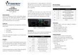
FIGURE 1 GbE ACCESS RINGS
The switches have a 1000BASE-T port for dedicated management access (which can be operated
outside the data channel). It has an SNMP-based management agent embedded on the main
board, which supports both in-band and out-of-band access using a Web browser, SNMP/RMON, or
Telnet.
MLX
CES
CES
IP/MPLS
6910
69106910
6910
MLX
10G Regional Ring
GbE Access
Ring

2 Brocade 6910 Ethernet Access Switch Hardware Installation Guide
53-1002580-01
Overview
1
FIGURE 2 FRONT PANEL Brocade 6910 Switch
1. AC Input
2. Port Status LEDs
3. Minor Alarm LED
4. Major Alarm LED
5. Alarm Port
6. Diag LED
7. Pow er LE D
8. Mgmt LED
9. RJ-45 Console & Management Ports
10. Reset Button
11. Combination RJ-45/SFP Ports
12. Grounding Points
FIGURE 3 FRONT PANEL Brocade 6910 Switch
1. DC Input
2. Port Status LEDs
3. System Status LEDs
4. Alarm Port
5. RJ-45 Console & Management Ports
6. Reset Button
7. Combination RJ-45/SFP Ports
5
2
4
1
3
6
78
9
1011
12
1
3
78
5
2
4
6

Brocade 6910 Ethernet Access Switch Hardware Installation Guide 3
53-1002580-01
Network Management Options
1
8. Grounding Points
FIGURE 4 SIDE PANEL
1. Ventilation
FIGURE 5 REAR PANEL
1. Ventilation
Switch Architecture
These switches employ a wire-speed, non-blocking switching fabric. This permits simultaneous
wire-speed transport of multiple packets at low latency on all ports.
Network Management Options
These switches contain a comprehensive array of LEDs for “at-a-glance” monitoring of network and
port status. They also include a management agent that allows you to configure or monitor the
switch using its embedded management software, or through SNMP applications. To manage the
switch, you can make a direct connection to the console port (out-of-band), or you can manage the
switch through a network connection (in-band) using Telnet, SSH, the on-board web agent, or
SNMP-based network management software.
The switch management port (RJ-45) provides a dedicated management channel that operates
outside of the data transport network. This makes it possible to re-configure or troubleshoot the
switch over either a local or remote connection to the port when access through the data channel is
not possible or deemed insecure.
For a detailed description of the switch’s advanced features, refer to the Brocade 6910 Ethernet
Access Switch Configuration Guide.
1
1

4 Brocade 6910 Ethernet Access Switch Hardware Installation Guide
53-1002580-01
Description of Hardware
1
Description of Hardware
The Brocade 6910 switches consist of two model types, one hardened for extended temperature
range environments, the other non-hardened for standard temperature range environments:
• Standard temperature range switches for 0 to +50 °C:
• BR-6910-EA-AC
• BR-6910-EA-DC
• Extended temperature range switches for -40 to +65 °C:
• BR-6910-EA-H-AC
• BR-6910-EA-H-DC
SFP Slots
The 12 Small Form Factor Pluggable (SFP) transceiver slots are shared with 12 RJ-45 ports. In its
default configuration, if an SFP transceiver (purchased separately) is installed in a slot and has a
valid link on its port, the associated RJ-45 port is disabled and cannot be used. The switch can also
be configured to force the use of an RJ-45 port or SFP slot, as required.
There are two types of SPF transceivers - one hardened that can operate at temperatures between
-40 to +65 °C, and non-hardened that can operate at temperatures between 0 to +50 °C.
The SFP slots support the following SFP transceivers:
• Standard temperature range optics (0 to +50 °C)
• 100Base-SX (OM) 33225-100
• 100Base-LX (OM) 33226-100
• 1000Base-SX (OM) 33210-100
• 1000Base-LX (OM) 33211-100
• 1000Base-LHA (OM) 33212-100
• 1000Base-LHB 33004-000
• 1000Base-BXU 33006-000
• 1000Base-BXD 33005-000
• 1000Base-CWDM
• Extended temperature range optics (-40 to +65 °C)
• 100Base-FX (OM) 33224-100
• 1000Base-SX (OM)
• 1000Base-LX (OM)
• 1000Base-LHA (OM)
For information on the recommended standards for fiber optic cabling, see “Fiber Optic Devices”
on page 24.

Brocade 6910 Ethernet Access Switch Hardware Installation Guide 5
53-1002580-01
Description of Hardware
1
10/100/1000BASE-T Ports
The switches contain 12 1000BASE-T RJ-45 ports that operate at 10 Mbps or 100 Mbps, half or full
duplex, or at 1000 Mbps, full duplex. Because all of the RJ-45 ports support automatic MDI/MDI-X
operation, you can use straight-through cables for all network connections to PCs or servers, or to
other switches or hubs. (See “1000BASE-T Pin Assignments” on page 29.)
Each of these ports support auto-negotiation, so the optimum transmission mode (half or full
duplex), and data rate (10, 100 or 1000 Mbps) can be selected automatically. If a device
connected to one of these ports does not support auto-negotiation, the communication mode of
that port can be configured manually. Each port also supports auto-negotiation of flow control, so
the switch can automatically prevent port buffers from becoming saturated.
10/100/1000BASE-T Management Port (The Craft Interface)
The 10/100/1000BASE-T port provides a dedicated management interface that is segregated
from the data traffic crossing the other ports. This port supports auto-negotiation, so the optimum
transmission mode (half or full duplex) and data rate (10, 100, or 1000 Mbps) can be selected
automatically, if this feature is also supported by the attached device. However, note that the
interface connection parameters of this port cannot be configured.
Console Port
The console port on the switch’s front panel is an RJ-45 connector that enables a connection to a
terminal for performing switch monitoring and configuration functions. The terminal may be a PC or
workstation running terminal emulation software, or a terminal configured as a Data Terminal
Equipment (DTE) connection. A null-modem wired serial cable is supplied with the switch for
connecting to this interface.
It is recommended that you use the cable provided with the box.
Flow control must be disabled to use the console port and port speed is 9600-N-8-1
Alarm Interface Port
The DB-15 alarm port on the switch’s front panel can be used to provide alarm, service port, and
BITS clock reference interfaces. The switch supports two sets of alarm relay contacts (major and
minor), and 4 external customer site alarm inputs. It also provides an alarm cutoff button (labeled
ACO). Refer to “Connecting to the Alarm Port” on page 20 for a description of the pin assignments
used to connect to the alarm port.
Port and System Status LEDs
This switch includes a display panel for key system and port indications that simplifies installation
and troubleshooting. The LEDs, which are located on the front panel for easy viewing, are shown
below and described in the following tables.

6 Brocade 6910 Ethernet Access Switch Hardware Installation Guide
53-1002580-01
Description of Hardware
1
FIGURE 6 PORT AND SYSTEM LEDs
1. Port Status LEDs
2. Major Alarm LED
3. Minor Alarm LED
4. Diag LED
5. Power LED
6. Mgmt LED
TABLE 1 SYSTEM STATUS LEDs
LED Condition Status
Major Alarm Green Indicates presence within the system of one or more major
traffic-affecting system alarm(s) that are not masked by the
alarm filter.
Off System is operating normally.
Minor Alarm Green Indicates presence within the system of one or more minor
traffic-affecting system alarm(s) that are not masked by the
alarm filter.
Off System is operating normally.
Diag Amber System self-diagnostic is in progress.
Green System self-diagnostic test successfully completed.
Mgmt Green The management port has a valid 1000BASE-T link.
Flashing Green Flashing indicates 1000BASE-T activity on the port.
Amber The management port has a valid 10/100BASE-TX link.
Flashing Amber Flashing indicates 10/100BASE-TX activity on the port.
Off The link is down.
Power Green DC or AC power is functioning normally.
Off External power not connected or has failed.
3
1 2
6
1
1211109
11
4
5
/