Delta T27967-SS Installation guide
- Category
- Sanitary ware
- Type
- Installation guide

MultiChoice
®
Valve Trim with Diverter
Installation Instructions
Owners Manual
Models T27
Write purchased model number here.
You May Need
THIS VALVE MEETS OR EXCEEDS THE
FOLLOWING STANDARDS: ASME A112.18.1/
CSA B125.1 and ASSE 1016 (Type -P- or -T-).
CAUTION: This system/device must be set by the
installer to ensure safe, maximum temperature.
Any change in the setting may raise the discharge
temperature above the limit considered safe and
may lead to hot water burns.
NOTICE TO INSTALLER: CAUTION!–As the
installer of this valve, it is your responsibility
to properly INSTALL and ADJUST this valve
per the instructions given. This valve does
not automatically adjust for inlet temperature
changes, therefore, someone must make the
necessary Rotational Limit Stop adjustments
at the time of installation and further adjustments
may be necessary due to seasonal water
temperature change. YOU MUST inform the
owner/user of this requirement by following
the instructions. If you or the owner/user are
unsure how to properly make these adjustments
please refer to page 6 and if still uncertain, call
us at 1-800-345-DELTA.
After installation and adjustment, you must afx
your name, company name and the date you
adjusted the Rotational Limit Stop to the caution
label provided and apply or attach the label to
the back side of the closest cabinet door and the
warning label to the water heater. Leave this
Instruction Sheet for the owner’s/user’s
reference.
WARNING: This pressure balanced or
thermostatic bath valve is designed
to minimize the effects of outlet water
temperature changes due to inlet pressure
changes, commonly caused by dishwashers,
washing machines, toilets and the like. It may
not provide protection from hot water burns
when there is a failure of other temperature
controlling devices elsewhere in the
plumbing system, if the rotational limit stop
is not properly set or if the hot water
temperature is changed after the settings are
made or if the water inlet changes
due to seasonal changes.
WARNING: Do not install a shut-off device on
either outlet of this valve. When this type of
device shuts off the water ow, it can defeat
the ability of the valve to balance the hot and
cold water pressures.
Rev. A1
104438
Table of Contents:
Warranties ............................................................................... Page 2
Installation Instructions ........................................................... Pages 3 - 7
Clean and care......................................................................... Page 9
Maintenance ............................................................................ Page 9
Cartridge Summary Reference Sheet ..................................... Page 9
For additional replacement parts, visit www.deltafaucet.com
01/24/2019
3/32"

104438 Rev. A
2
Parts and Finish. All parts (other than electronic parts and batteries) and finishes of this Delta
®
faucet are warranted to
the original consumer purchaser to be free from defects in material and workmanship for as long as the original consumer
purchaser owns the home in which the faucet was first installed. For commercial purchasers, the warranty period is ten (10)
years for multi-family residential (apartments and condominiums) and five (5) years for all other commercial uses, in each
case from the date of purchase.
Electronic Parts and Batteries (if applicable). Electronic parts (other than batteries), if any, of this Delta
®
faucet are war-
ranted to the original consumer purchaser to be free from defects in material and workmanship for five (5) years from the date
of purchase or, for commercial purchasers, for one (1) year from the date of purchase. No warranty is provided on batteries.
What We Will Do. Delta Faucet Company will repair or replace, free of charge, during the applicable warranty period (as
described above), any part or finish that proves defective in material and/or workmanship under normal installation, use and
service. If repair or replacement is not practical, Delta Faucet Company may elect to refund the purchase price in exchange
for the return of the product. These are your exclusive remedies.
What Is Not Covered. Any labor charges incurred by the purchaser to repair, replace, install or remove this product are not
covered by this warranty. Delta Faucet Company shall not be liable for any damage to the faucet resulting from reasonable
wear and tear, outdoor use, misuse (including use of the product for an unintended application), freezing water, abuse,
neglect or improper or incorrectly performed installation, maintenance or repair, including failure to follow the applicable care
and cleaning instructions. Delta Faucet Company recommends using a professional plumber for all installation and repair of
faucets. We also recommend that you use only genuine Delta
®
replacement parts.
What You Must Do To Obtain Warranty Service or Replacement Parts. A warranty claim may be made and replacement
parts may be obtained by calling 1 800 345 DELTA (3358) or by contacting us by mail or online as follows (please include
your model number and date of purchase):
In the United States and Mexico: In Canada:
Delta Faucet Company Masco Canada Limited, Plumbing Group
Product Service Technical Service Centre
55 E. 111th Street 350 South Edgeware Road
Indianapolis, IN 46280 St. Thomas, Ontario, Canada N5P 4L1
Attention: Customer Solutions Attention: Customer Service
www.deltafaucet.com/service-parts/contact-us http://www.deltafaucet.ca/customersupport/assistance.html
Proof of purchase (original sales receipt) from the original purchaser must be made available to Delta Faucet Company for
all warranty claims unless the purchaser has registered the product with Delta Faucet Company. This warranty applies only
to Delta
®
faucets manufactured after January 1, 1995 and installed in the United States of America, Canada and Mexico.
Limitation on Duration of Implied Warranties. TO THE EXTENT PERMITTED BY LAW, ANY IMPLIED WARRANTY,
INCLUDING THE IMPLIED WARRANTIES OF MERCHANTABILITY AND OF FITNESS FOR A PARTICULAR PURPOSE,
IS LIMITED TO THE STATUTORY PERIOD OR THE DURATION OF THIS WARRANTY, WHICHEVER IS SHORTER. Some
states/provinces do not allow limitations on how long an implied warranty lasts, so the above limitation may not apply to you.
Limitation of Special, Incidental or Consequential Damages. DELTA FAUCET COMPANY SHALL NOT BE LIABLE FOR
ANY SPECIAL, INCIDENTAL OR CONSEQUENTIAL DAMAGES (INCLUDING LABOR CHARGES TO REPAIR, REPLACE,
INSTALL OR REMOVE THIS PRODUCT), WHETHER ARISING OUT OF BREACH OF ANY EXPRESS OR IMPLIED
WARRANTY, BREACH OF CONTRACT, TORT, OR OTHERWISE. DELTA FAUCET COMPANY SHALL NOT BE LIABLE
FOR ANY DAMAGE TO THE FAUCET RESULTING FROM REASONABLE WEAR AND TEAR, OUTDOOR USE, MISUSE
(INCLUDING USE OF THE PRODUCT FOR AN UNINTENDED APPLICATION), FREEZING WATER, ABUSE, NEGLECT
OR IMPROPER OR INCORRECTLY PERFORMED INSTALLATION, MAINTENANCE OR REPAIR, INCLUDING FAILURE
TO FOLLOW THE APPLICABLE INSTALLATION, CARE AND CLEANING INSTRUCTIONS. Some states/provinces do not
allow the exclusion or limitation of special, incidental or consequential damages, so the above limitations and exclusions may
not apply to you. Notice to residents of the State of New Jersey: The provisions of this warranty, including its limitations, are
intended to apply to the fullest extent permitted by the laws of the State of New Jersey.
Additional Rights. This warranty gives you specific legal rights, and you may also have other rights which vary from state/
province to state/province.
This is Delta Faucet Company’s exclusive written warranty and the warranty is not transferable.
If you have any questions or concerns regarding our warranty, please contact us as provided above or view our Warranty
FAQs at www.deltafaucet.com.
Limited Warranty on Delta
®
Faucets
© 2019 Delta Faucet Company

104438 Rev. A
Installation
1
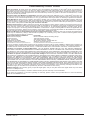
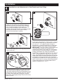
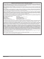
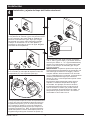
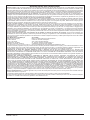
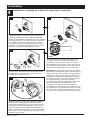
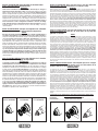
Cartridge Installation
A.
B.
Turn off water supplies. Remove cover (1),
bonnet nuts (2) and test caps (3) from the
rough-in body (4).
Place a bucket or small container over the front
of the valve body and slowly open the water
supplies to ush any debris from the supply
lines before installing the cartridge. Turn the
water supplies back off.
Insert adapter assembly (1) into rough-in
body (2). Make sure the adapter assembly
is correctly positioned and is pressed all
the way down inside rough-in body.
Rotate cartridge (1) so the words “HOT SIDE”
(2) appear on the left. Insert cartridge assembly
into rough-in body. Make sure the key (3) on the
valve cartridge is fully engaged with the slot in
the brass body (4). Insert bonnet nut (5) over
the cartridge and thread onto the body. Hand
tighten securely, slide o-ring (6) over bonnet
and cartridge. A light coating of plumbers
grease applied to o-rings may aid in assembly.
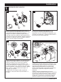
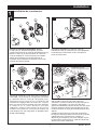
For the exceptions of back to back or reverse
installations (hot on right and cold on left) only:
Rotate valve cartridge (1) so “HOT SIDE” (2)
appears on the right.
Apply silicone lube to the three o-rings shown
above to make the cartridge easier to install and
remove from the rough-in body.
Install the cartridge making sure that the keys
are fully engaged with the slot in the rough-in
body (see step C).
Slide o-ring (3) and bonnet nut (4) over the
cartridge and thread onto the rough-in body.
Hand tighten securely.
3
C.
Back to back Installation
Normal Installation
(changes not required)
Reverse
Installation
Cold
Hot
1
2
3
4
2
3
1
2
1
2
3
4
5
3
4
2
4
3
1
6

104438 Rev. A
Installation
2
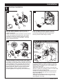
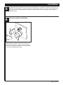
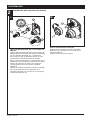
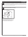
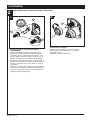
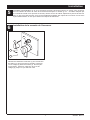
Diverter Cartridge Installation
4
For Bonnet Installation
Slide bonnet nut (1) over diverter sleeve (2)
and thread into rough-in body.
Hand tighten securely.
B.
FOR DIVERTER CARTRIDGE
INSTALLATION:
Apply silicone lube to the o-ring (2) to make
the diverter sleeve (3) easier to install diverter
cartridge. A light coating of plumbers grease
applied to o-rings (4) may aid in assembly.
Install diverter cartridge (1) assuring that the
locating pin on the bottom of the cartridge
aligns with mating hole in rough-in body.
Slide diverter sleeve (3) over cartridge stem
aligning tabs on the diverter sleeve with slots
in rough-in body (5).
A.
3
1
5
2
1
2
5
4

104438 Rev. A
Installation
3
5
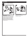
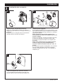
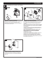
Trim Installation
Trim Sleeve Installation
Slide trim sleeve (1) over the bonnet (2),
cartridge and rough-in body.
Ensure sleeve is properly positioned over the
front of cartridge.
Escutcheon Installation
For nished wall thickness up to 1 1/8". Secure
the backplate (1) to the rough-in body (2) using 4
screws (3) provided.
Note: Be sure backplate is oriented front side
forward and markings are visible.
Slide escutcheon (4) over diverter cartridge,
thread trim nut (5) onto diverter sleeve (6).
Note: For thick wall installations, order
installation kit RP90543 to support nished
wall thickness up to 2 1/8".
On rough or uneven surfaces it is necessary
to apply caulk around the backplate (1) to
supplement the seal. Do not caulk the drip notch
in the bottom of the backplate (1). Do not caulk
the escutcheon (4).
1
2
A. B.
1
2
5
4
Install volume control handle (1) with lever
pointing down, then turn to the on position.
DO NOT SECURE WITH SCREW.
3
3
6
Drip notch
7
C.
1

104438 Rev. A
Installation
4
6
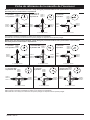
Installation and Adjustment of the Rotational Limit Stop
Place the rotational limit stop (1) in
volume
handle (2) and rotate to the mixed
position (if
required). DO NOT SECURE WITH
SCREW.
Turn on water supplies; let the
water
run until
both hot and cold water is as hot/
cold as
possible. Place thermometer in a plastic tumbler,
and hold the tumbler in the water stream.
Record the temperature reading.
If the water temperature is above 120°F, remove
and rotate the limit stop (1) clockwise one tooth
for every 4°F - 6°F (approximate) change in
temperature. If water temperature is cooler than
desired, rotate the limit stop counterclockwise.
IMPORTANT: The rst position of the Rotational
Limit Stop (the Limiter) is the position that
restricts the rotation of the stem the most and is
at the maximum clockwise setting. According to
industry standards, the maximum allowable
temperature of the water exiting from the valve is
120
o
F. This temperature may vary in your local
area. The Rotational Limit Stop may need to be
readjusted if the inlet water temperature changes.
For instance, during the winter, the cold water
temperature is colder than it is during the summer
which could result in varying outlet temperatures.
Typical temperature for a comfortable bath or
shower is between 90
o
–110
o
F.
Secure temperature control knob (1) with screw
(2). See next step (D) for securing temperature
control cover (3).
Snap temperature control cover over temperature
control knob by rst aligning smaller tab (1) on
cover with receiving slot (2) on temperature knob.
Swing larger tab (3) to engage with snap feature
(4). Note: If dis-assembly is required, reverse
this motion, disengaging larger tab (3) from snap
feature (4) rst.
D.
4
2
1
3
B.
Hotter
Colder
1
A.
1
C.
1
2
3
2

104438 Rev. A
Potential scald or thermal shock injury could result due to cross ow if outlet at the shower is
blocked or restricted (e.g., pause control on showerhead). Be sure to point showerhead away
from you when re-starting ow or install inlet check valves on both supply lines to prevent
possible injury.
7
6
Diverter handle Installation
Diverter Handle Installation
Slide diverter handle (1) onto trim sleeve (2).
Using a allen wrench, insert set screw (3) into
handle (1). Applying pressure, insert set screw
cover (4) until properly seated.
Installation
5
2
1
3
4
Page is loading ...

104438 Rev. A
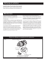
Clean and Care
Care should be given to the cleaning
of this product. Although its nish is
extremely durable, it can be damaged by
harsh abrasives or polish. To clean, simply
wipe gently with a damp cloth and blot dry
with a soft towel.
Maintenance
Faucet leaks from showerhead:
SHUT OFF WATER SUPPLIES.
Replace valve cartridge
RP46463 or RP32104
See Helpful Hints 1, 2, 3 & 4.
Helpful Hints:
1. Before removing valve cartridge assembly for any
maintenance, be sure to note the position of the
rotational limit stop on the cap. The valve cartridge
assembly must always be put back in the same
position. BE SAFE! After you have nished the
installation, turn on valve to make sure COLD
WATER FLOWS FIRST.
2. To remove valve cartridge from body, shut off
water supplies and remove handle and bonnet nut.
Do not pry the valve cartridge out of the body with
a screwdriver. Place handle on stem and rotate
counterclockwise approximately 1/4 turn after the
stop has been contacted. Lift valve cartridge out
of body.
Remove seats and springs and replace.
Place the largest diameter of the spring into the
seat pocket rst and then press the tapered end
of the seal over the spring. Reassemble valve
cartridge and replace in body following instructions
given in 1 above.
3. If the water in your area has lime, rust, sand
or other contaminants in it, your pressure
balance valve will require periodic inspection.
The frequency of the inspection will depend
on the amount of contaminants in the water. To
inspect valve cartridge remove it and follow the
steps in note 1 above. Turn the valve to the full
mix position and shake the cartridge vigorously.
If there is a rattling sound, the unit is functional
and can be reinstalled following instructions given
in note 1 above. If there is no rattle, replace the
housing assembly with the proper RP.
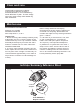
Cartridge Summary Reference Sheet
Order RP46463 to
Replace Cartridge.
Grey Upper Cap
V Notch
Adapter
Shorter Tab
T27
9
Page is loading ...
Page is loading ...
Page is loading ...
Page is loading ...
Page is loading ...
Page is loading ...
Page is loading ...
Page is loading ...
Page is loading ...
Page is loading ...
Page is loading ...
Page is loading ...
Page is loading ...
Page is loading ...
Page is loading ...
Page is loading ...
Page is loading ...
Page is loading ...
Page is loading ...
Page is loading ...

104438 Rev. A
10
Notes/Notas/Notes

104438 Rev. A
11
Notes/Notas/Notes

104438 Rev. A
Delta Faucet Company
Product Service
55 E. 111th Street
Indianapolis, IN 46280

IMPORTANT DOCUMENTS ENCLOSED
CAUTION:
To reduce the risk of injury due to hot water
burns, make sure the enclosed labels are
applied where specied on the label.
DOCUMENTOS IMPORTANTES INCLUIDOS
AVISO:
Para reducir el riesgo de lesión por
quemaduras de agua caliente , asegúrese que
las etiquetas incluidas se han aplicado donde
se ha especicado en la etiqueta.
DOCUMENTS IMPORTANTS À L’INTÉRIEUR
MISE EN GARDE :
Pour réduire le risque d’ébouillantage, veuillez
apposer les étiquettes fournies aux endroits
indiqués sur celles-ci.

NOTICE TO INSTALLER: Place this label close to the valve where the
owner will see it, such as inside the door of a cabinet or vanity.
WARNING
Water temperature changes due to seasonal or other inlet variations, such as changing the setting on
the hot water heater may require adjustment of the rotational limit stop ortemperature knob on your tub/
shower valve to ensure a safe maximum temperature. These valve series do not automatically adjust for
inlet temperature changes. If changes occur and you are not sure how to make the necessary rotational
limit stop or temperature knob adjustments, please consult the installation instruction sheet provided
with this valve or call 1-800-345-DELTA. These valve series are designed to minimize the effects of
outlet water temperature changes due to inlet pressure changes, commonly caused by dishwashers,
washing machines, toilets and the like.
They may not provide protection from hot water burns when
there is a failure of other temperature controlling devices elsewhere in the plumbing system.
After making the necessary adjustments please ll in the information below. This valve/system has been
set by the person listed below to ensure a safe maximum temperature. Any change in the setting may
raise the discharge temperature above the limit considered safe and could lead to hot water burns. If
this label has not been completed, you should verify that the rotational limit stop or temperature knob
has been properly adjusted to suit your individual installation. The installation instruction sheet supplied
with the valve provides information on how to make this setting.
AVISO AL INSTALADOR: Coloque esta etiqueta cerca de la válvula
donde el propietario la pueda ver, tal como dentro de la puerta del
gabinete o el tocador.
AVISO:
Los cambios de temperatura del agua por variaciones estacionales u otras variaciones en el agua
de entrada, como el cambio por el ajuste en el calentador de agua, puede requerir el ajuste del tope
del límite rotacional o ajuste de la perilla para el control de la temperatura de la válvula de su unidad
bañera/regadera para asegurar una temperatura máxima segura. Esta serie de válvulas no se ajusta
automáticamente para los cambios de temperatura del agua de entrada. Si cambios ocurren y usted
no está seguro como hacer los ajustes necesarios con la perilla para controlar la temperatura, por
favor consulte la hoja de instrucciones de instalación proporcionada con esta válvula o llámenos al
1-800-345-DELTA. Las válvulas de esta serie están diseñadas para minimizar los efectos por cambios
de temperatura en el agua de entrada por cambios en la presión del agua, comúnmente causados por
el uso simultáneo de fregadoras de platos, lavadoras, inodoros y aparatos similares.
Estas pueden
no proporcionar protección de quemaduras por el agua caliente cuando hay una falla de otros
mecanismos que controlan la temperatura del agua en otro sitio del sistema de plomería.
Después de hacer los ajustes necesarios, por favor escriba la información suministrada a continuación.
Esta válvula/sistema ha sido ajustada por la persona indicada a continuación para ayudar a asegurar
una temperatura máxima segura. Cualquier cambio al ajuste puede aumentar la temperatura del agua
de descarga sobre el límite considerado seguro y puede resultar en quemaduras por agua caliente.
Si esta etiqueta no se ha llenado, debe vericar si el control o tope del límite rotacional o la perilla que
controla la temperatura han sido correctamente ajustadas al gusto de su instalación individual. La hoja
de instrucciones de instalación proporcionada con las válvulas le suministra información sobre como
hacer este ajuste.
AVIS À L’INSTALLATEUR: Placez cette étiquette près de la soupape
à un endroit où le propriétaire pourra la voir, du côté intérieur de la
porte de l’armoire ou du meuble par exemple.
AVERTISSEMENT:
La température de l’eau peut varier en raison des changements de saison, d’une modification
du réglage du chauffe-eau ou d’autres changements. Par conséquent, un réglage du bouton de
température de votre soupape de douche ou de baignoire peut s’imposer pour que la température
maximale de l’eau demeure sécuritaire. Les soupapes de cette série ne s’ajustent pas automatiquement
aux changements de température de l’eau d’alimentation. Si des changements vous obligent à régler
le bouton de température et vous n’êtes pas certain de la marche à suivre, veuillez consulter le feuillet
d’instructions fourni avec la soupape ou appeler au 1-800-345-DELTA. Cette soupape est conçue pour
réduire les risques de blessures causées par des changements de la température ou de la pression de
l’eau d’alimentation habituellement causés par le lave-vaisselle, la machine à laver, une toilette ou un
autre appareil qui consomme de l’eau.
Elle peut ne pas assurer de protection contre l’ébouillantage
en cas de défectuosité d’un autre dispositif de régulation de la température dans la tuyauterie.
Après avoir effectué le réglage nécessaire, veuillez inscrire l’information requise ci-dessous. La
personne dont le nom figure ci-dessous a réglé cette soupape pour qu’elle puisse maintenir une
température maximale sécuritaire. Toute modication du réglage peut entraîner une élévation de la
température de l’eau s’écoulant par la douche ou dans la baignoire au delà de la limite considérée
sécuritaire, ce qui pourrait causer un ébouillantage. Si cette étiquette n’a pas été remplie, vous devriez
vous assurer que le bouton de température a été réglé en fonction des caractéristiques de votre
installation. Le feuillet d’instruction fourni avec la soupape indique la marche à suivre pour effectuer le
réglage.
BY/POR/PAR _______________ COMPANY/COMPANIA/COMPAGNIE ________________
DATE/FECHA/LE ___________ PHONE/TELÉFONO/TELÉPHONE ____________________
TO BE FILLED OUT BY THE INSTALLER / PARA SER LLENADO POR EL INSTALADOR /
A REMPLIR PAR L’INSTALLATEUR:
13 / 14 / 24 Series
17 / 27 Series
17T / 27T Series
NOTICE TO INSTALLER: Place this label on the water heater
next to the temperature adjustment knob.
WARNING:
These series of tub/shower valves do not adjust automatically for changes in
temperature at the hot water heater or inlet.
If the temperature setting of the hot water
heater or inlet is changed, the setting on these valves
must be adjusted manually!
Failure to re-adjust the valve may result in hot water burns or extreme cold resulting from
variations in line pressure (such as when a dishwasher or washing machine is in use
while you are taking a shower). After installation, verify that the rotational limit stop or
temperature knob on the valve is set so that changes in line pressure or temperature do
not result in uncomfortable water temperature changes.
If the temperature setting of
the hot water heater or inlet is changed after installation of the valve, the setting
of the rotational limit stop or temperature knob also must be changed!
Consult the
installation instruction sheet for instructions on how to make this setting, or call us at
1-800-345-DELTA.
AVISO AL INSTALADOR: Coloque esta etiqueta en el calentador
de agua al lado de la perilla para el ajuste de temperatura.
AVISO:
Esta serie de válvulas para bañeras/regaderas no se ajustan automáticamente a
los cambios de temperatura en el calentador de agua o en el agua de entrada.
Si
el ajuste de la temperatura del calentador de agua o la temperatura del agua que entra
cambia
¡El ajuste de estas válvulas se debe hacer manualmente!
El no reajustar
la válvula puede resultar en quemaduras por agua caliente o temperaturas de agua
extremadamente frías resultando en variaciones de presión y temperatura (como
cuando el fregador de platos o la lavadora están funcionando mientras que se baña).
Después de la instalación, verique que el control o tope del límite rotacional o la perilla
del control de temperatura en la válvula está ajustada para que los cambios de presión
y de temperatura en la línea no resulten en cambios incómodos de temperatura del
agua.
Si el ajuste de la temperatura del calentador de agua o de la entrada de agua
se cambia después de la instalación de la válvula, el ajuste del tope del límite
rotacional o la perilla de ajuste ¡también se debe cambiar!
Consulte con su hoja de
instrucciones de instalación para saber como se ajusta o cambia el ajuste, o llámenos al
1-800-345-DELTA.
AVIS À L’INSTALLATEUR: Fixez cette étiquette sur le chauffe-
eau près du bouton de réglage de température.
ATTENTION :
La soupape de robinet de baignoire ou de douche de cette série ne se règle pas
automatiquement en fonction des changements de température de l’eau chaude
au chauffe-eau ou de l’eau d’alimentation.
En cas de modification du réglage de
température du chauffe-eau ou de la température de l’eau d’alimentation, le réglage
de cette soupape doit
être modié manuellement!
Si le réglage de la soupape n’est
pas modié, le robinet pourra permettre l’écoulement d’eau très chaude susceptible de
causer l’ébouillantage ou d’eau très froide, sous l’effet des variations de pression et de
température dans la tuyauterie d’alimentation (lorsque la douche est utilisée en même
temps que le lave-vaisselle ou la machine à laver, par exemple). Après l’installation,
assurez-vous que la butée de température maximale ou le bouton de température sur la
soupape est réglé de manière que les uctuations de pression et de température dans
la tuyauterie d’alimentation n’entraînent pas de changements de température de l’eau
inconfortables.
En cas de modication du réglage de température du chauffe-eau
ou de la température de l’eau d’alimentation après l’installation de la soupape, le
réglage de la butée de température maximale ou du bouton de température doit
être modié!
Pour régler le bouton de température, consultez la feuille d’instructions
d’installation ou appelez-nous au 1-800-345-DELTA.
13 / 14 / 24 Series
17 / 27 Series 17T / 27T Series
-
 1
1
-
 2
2
-
 3
3
-
 4
4
-
 5
5
-
 6
6
-
 7
7
-
 8
8
-
 9
9
-
 10
10
-
 11
11
-
 12
12
-
 13
13
-
 14
14
-
 15
15
-
 16
16
-
 17
17
-
 18
18
-
 19
19
-
 20
20
-
 21
21
-
 22
22
-
 23
23
-
 24
24
-
 25
25
-
 26
26
-
 27
27
-
 28
28
-
 29
29
-
 30
30
-
 31
31
-
 32
32
-
 33
33
-
 34
34


Delta T27967-SS Installation guide
- Category
- Sanitary ware
- Type
- Installation guide
Ask a question and I''ll find the answer in the document
Finding information in a document is now easier with AI
in other languages
- français: Delta T27967-SS Guide d'installation
- español: Delta T27967-SS Guía de instalación
Related papers
-
Delta RP46074 Installation guide
-
-
-
Delta Faucet T24859-SS Installation guide
-
Delta Faucet T27T867 Installation guide
-
Delta Faucet T11976-RB Installation guide
-
Delta T17464-I User manual
-
Delta T27867 Installation guide
-
Cooper 1700 Series Installation guide
-
Other documents
-
-
-
-
-
-
-
-
-
-