Safety Instructions
Preparation Installation
Final Steps
English • 4
Your Life ...
Step 5: Prepare Electrical Connection
Install Strain Relief
Place strain relief in knockout below terminal block (See
Figure 4). Feed range cord through hole and strain relief
up to terminal block. Allow for slack in the cord between
the strain relief and terminal block. Once cord length/
slack has been adjusted, attach strain relief per
instructions included with strain relief.
TIP
The knockout panel below the terminal block can be
removed from the range to install the strain relief:
Remove knockout panel from range, install strain
relief in panel and reattach. DO NOT remove entire
range back panel.
Verify that wiring to house is adequate.
Contact your local utility company to verify that the present
electric service to your home is adequate. In some
instances, the size of the wiring to the house and service
switch must be increased to handle the electrical load
demanded by the range.
Verify that wiring inside house is adequate.
Most wiring codes require a separate circuit with separate
disconnect switch and fuses either in the main entrance
panel or in a separate switch and fuse box.
The range requires a three wire 120/240 or 120/208 volt,
30 AMP, 60 Hz AC circuit.
Most local building regulations and codes require that
electrical wiring be done by licensed electricians. Be sure
to install your range according to the electric codes in
place in your region.
General Information
Bosch recommends that the range be installed with a
power cord set (not supplied)*. The electrical rating of the
power cord set must be 120/240 volt, 30 amperes
minimum. The power cord set shall be marked “For Use
with Ranges.” Always use a new power cord.
Note: In Canada, the range is shipped from the factory
with the range cord already installed. Proceed to “Step 7:
Installation - Connect the Gas Supply)
For installations other than those in Canada, connect the
range cord at the terminal block (See next page for
detailed instructions). Access the terminal block by
removing the cover in the lower right hand corner of the
range back panel (See Figure 4). Install the strain relief
(see next column) and the proper connector through the
knockout(s) provided. The electrical supply, including
flexible conduit or power cord, should be restricted to the
shaded areas in Figure 2 (previous page)
WARNING
The strain relief provided with your range
cord must be properly installed.
To prevent electrical shock, the grounding
prong on the range cord should not be cut or
removed under any circumstances. It must be
plugged into a matching grounding type receptacle and
connected to a correctly polarized 240- Volt circuit. If
there is any doubt as to whether the wall receptacle is
properly grounded, have it checked by a qualified
electrician.
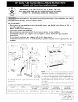
Figure 4
Electric Connection (found
behind terminal block
cover)
Gas Connection
Feed
Range
Cord
Through
Strain
Relief in
Knockout
Panel
Here
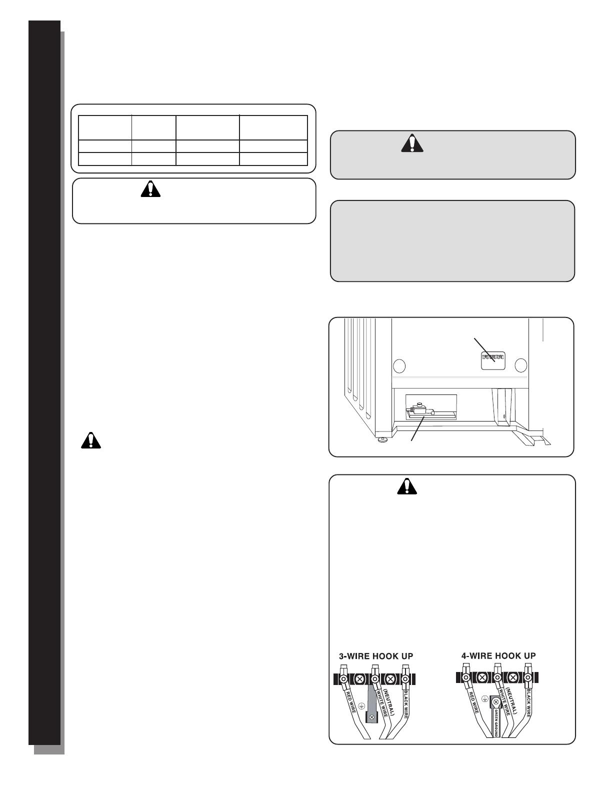
Figure 5
WARNING
Risk of Electric Shock or Fire. Frame grounded to neutral
through a ground strap. Grounding through the neutral
conductor is prohibited for new branch-circuit installations
(1996 NEC), mobile homes, and recreational vehicles, or in an
area where local codes prohibit grounding through the neutral
conductor.
For installations where grounding through the neutral
conductor is prohibited, (a) disconnect the link from the neutral,
(b) use grounding terminal or lead to ground unit, (c) connect
neutral terminal to lead branch circuit neutral in usual manner
(when the appliance is to be connected by means of a cord kit,
use 4-conductor cord for this purpose).
Use only cord kits rated 125/250 volts (minimum), 30 amperes
and labeled “For Use with Ranges”. Strain relief provided with
cord must be installed per instructions included with cord.
5. Prepare Electrical Connection
Ranges are dual rated for use on either 120/240 VAC or
120/208 VAC. See chart below for power ratings and
circuit breaker sizes based on the supply voltage for
each model.
CAUTION:
Make certain that gas shutoff valve and all burner
controls are in the OFF position before beginning
MODEL: HDS
VOLTS HZ RATING CIRCUIT
A.C. KW BREAKER
120/240 60 6.5 30 AMPS
120/208 60 4.8 30 AMPS
* Not needed for Canadian installations