Bosch 00466148 Installation guide
- Category
- Cooker hoods
- Type
- Installation guide

Bosch
ventilation installation
manual
DUH Models

2
PLEASE READ ENTIRE INSTRUCTIONS BEFORE PROCEEDING.
INSTALLATION MUST COMPLY WITH ALL LOCAL CODES.
IMPORTANT: Save these Instructions for the Local Electrical Inspector’s use.
INSTALLER: Please leave these Instructions with this unit for the owner.
OWNER: Please retain these instructions for future reference.
Safety Warning: Turn off power circuit at service panel and lock out panel, before wiring this appliance.
Requirement: 120 V AC, 60 Hz. 15 or 20 A Branch Circuit
APPROVED FOR RESIDENTIAL APPLIANCES
FOR RESIDENTIAL USE ONLY
READ AND SAVE THESE INSTRUCTIONS

3
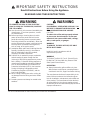
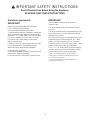
IMPORTANT SAFETY INSTRUCTIONS
Read All Instructions Before Using the Appliance.
READ AND SAVE THESE INSTRUCTIONS
WARNING
TO REDUCE THE RISK OF FIRE, ELECTRIC
SHOCK, OR INJURY TO PERSONS, OBSERVE
THE FOLLOWING:
A. Use this unit only in the manner intended by the
manufacturer. If you have questions, contact
the manufacturer.
B. Before servicing or cleaning the unit, switch
power off at service panel and lock service
panel disconnecting means to prevent power
from being switched on accidentally. When the
service disconnecting means cannot be locked,
securely fasten a prominent warning device,
such as a tag, to the service panel.
C. Installation Work and Electrical Wiring Must Be
Done By Qualified Person(s) In Accordance
With All Applicable Codes & Standards,
Including Fire-rated Construction.
D. Sufficient air is needed for proper combustion
and exhausting of gases through the flue
(chimney) of fuel burning equipment to prevent
back- drafting. Follow the heating equipment
manufacturers guideline and safety standards
such as those published by the National Fire
Protection Association (NFPA), the American
Society for Heating, Refrigeration and Air
Conditioning Engineers (ASHRAE), and the
local code authorities.
E. When cutting or drilling into wall or ceiling, do
not damage electrical wiring and other hidden
utilities.
F. Ducted systems must always be vented to the
outdoors.
WARNING
CAUTION
FOR GENERAL VENTILATING USE ONLY. DO
NOT USE TO EXHAUST HAZARDOUS OR
EXPLOSIVE MATERIALS OR VAPORS.
CAUTION
To reduce risk of fire and to properly exhaust
air, be sure to duct air outside - do not vent
exhaust air into spaces within walls, ceilings,
attics, crawl spaces, or garages.
WARNING
TO REDUCE THE RISK OF FIRE, USE ONLY
METAL DUCT WORK.
Install this hood in accordance with all
requirements specified.
WARNING
To Reduce The Risk Of Fire Or Electric Shock,
Do Not Use This Hood With Any External Solid
State Speed Control Device.
OPERATION
a. Always leave safety grills and filters in place.
Without these components, operating blowers
could catch onto hair, fingers and loose clothing.
The manufacturer declines all responsibility in the
event of failure to observe the instructions given
here for installation, maintenance and suitable use
of the product. The manufacturer further declines
all responsibility for injury due to negligence and
the warranty of the unit automatically expires due to
improper maintenance.
This unit is manufactured for indoor use only. Do not use this unit outdoors.

4
Electrical requirements
IMPORTANT
Observe all governing codes and ordinances.
It is the customer’s responsibility:
To contact a qualified electrical installer.
To assure that the electrical installation is adequate
and in conformance with National Electrical Code,
ANSI/NFPA 70 — latest edition*, or CSA Standards
C22.1-94, Canadian Electrical Code, Part 1 and
C22.2 No.0-M91 - latest edition** and all local
codes and ordinances.
If codes permit and a separate ground wire is used,
it is recommended that a qualified electrician
determine that the ground path is adequate.
Do not ground to a gas pipe.
Check with a qualified electrician if you are not sure
range hood is properly grounded.
Do not have a fuse in the neutral or ground circuit.
IMPORTANT
Save Installation Instructions for electrical
inspector’s use.
The range hood must be connected with copper
wire only.
The range hood should be connected directly to the
fused disconnect (or circuit breaker) box through
metal electrical conduit.
Wire sizes must conform to the requirements of the
National Electrical Code ANSI/NFPA 70 — latest
edition*, or CSA Standards C22.1-94, Canadian
Electrical Code Part 1 and C22.2 No. 0-M91 - latest
edition** and all local codes and ordinances.
A U.L.- or C.S.A.-listed conduit connector must be
provided at each end of the power supply conduit
(at the range hood and at the junction box).
Copies of the standards listed may be obtained from:
* National Fire Protection Association Batterymarch Park
Quincy, Massachusetts 02269
** CSA International 8501 East Pleasant Valley Road
Cleveland, Ohio 44131-5575
IMPORTANT SAFETY INSTRUCTIONS
Read All Instructions Before Using the Appliance.
READ AND SAVE THESE INSTRUCTIONS

5
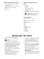
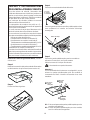
Parts Included with your Hood
• Hood Canopy Assembly with Round Metal
Transition installed.
• Rectangular Metal Transition with Back draft
dampers.
• Care & Use /Installation Instructions
• 2 Filters
• Fitting Screws.
Parts Not Included with your
Hood
• Duct Tape
• 1/2" Conduit
• Wire Nuts
• Round or Rectangular Duct.
• Charcoal filters
• Round back draft damper
• Wiring clamp
• Models DUH30252UC and DUH36252UCOnly:
CAUTION! Lamps are not supplied, use
ONLY 120 Volt, 50 Watt (maximum) 50°
halogen light made or a GU10 base.
Tools required
Flat blade and Phillips screwdrivers
Pencil
Metal snips (in some applications)
Electric drill
Saw (saber or keyhole)
Duct tape
Pliers
Level
Caulking
Tape measure
1/4.pivoting hex socket
Flashlight
Wire stripper
1/4. Nutdriver
Small hammer
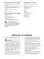
INSTALLING THE HOOD
• For the most efficient air flow exhaust, use a
straight run or as few elbows as possible.
CAUTION: Vent unit to outside of
building, only.
• One person is necessary for installation.
On avarage 2 hours are necessary to complete
installation (without considering cut to be done
on wall and or on cabinet, installation of ducts ,
conduit and electrical connections to the mains).
16 installation steps are required.
• The hood is fitted with Screws and Drywall
Anchors suitable for most surfaces, consult a
Qualified Installer, check if they perfectly fit with
your cabinet/wall.
• Do not use flex ducting.
• COLD WEATHER installations should have an
additional backdraft damper installed to
minimize backward cold air flow and a
nonmetallic thermal break to minimize
conduction of outside temperatures as part of
the ductwork. The damper should be on the
cold air side of the thermal break.
The break should be as close as possible to
where the ducting enters the heated portion of
the house.
• Remote blowers require a five wire installation.
• Make up air: Local building codes may require
the use of Make-Up Air Systems when using
Ducted Ventilation Systems greater than
specified CFM of air movement.
The specified CFM varies from locale to locale.
Consult your HVAC professional for specific
requirements in your area.
• Typical installation
Min installation height from the countertop to the
bottom of the hood is 24” to 30“.These hoods
are not recommended to be used over indoor
grills.

6
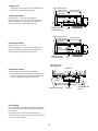
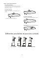
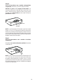
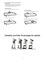
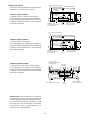
1. Choose vent options
Vent Exhaust Option
The hood is designed for vertical or horizontal
discharge or can be installed in a recirculating
ductless version:
Vertical discharge:
Use a rectangular duct 3 1/4” x 10”.....
....or use a round 7” duct
Horizontal discharge:
Use a rectangular duct 3 1/4” x 10”
Recirculating (non vented ductless)
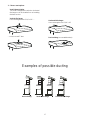
Examples of possible ducting
Horizontal dischargeVertical dischargeRecirculating

7
TOTAL (of both columns)=

8
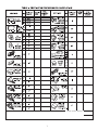
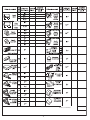
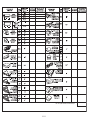
TABLE 2. DUCTWORK
INSTALLATION GUIDELINES
For safety reasons, ducting should vent directly
outdoors (not into an attic, underneath the
house, into the garage or into any enclosed
space).
Keep duct runs as short and straight as
possible.
Duct fittings (elbows and transitions) reduce air
flow efficiency.
Back to back elbows and „S“ turns give very
poor delivery and are not recommended.
A short straight length of duct at the inlet of the
remote blower gives the best delivery.
Transition to duct from the integral blower or
remote duct transition as close to the downdraft
as is pos-sible.
In order of preference, use
1st. 10" round duct
2nd. 8" round duct
3rd. 3-1/4" x 14" duct
4th. 7" round duct
5th. 3-1/4" x l0" duct
6th. 6" round duct
The use of flexible metal round duct should
only be used when no other duct fitting exists.
Limit use to short lengths and do not crush
when making corners.
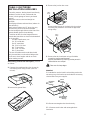
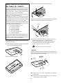
After having choosen the vent option, proceed
as follows:
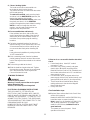
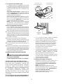
2. Remove the round transition from its seat by
unscrewing the its fixing screws (save the
screws).
7" Round
Transition
3. Remove the grease filters.
4. Remove the junction box cover.
J-Box
Cover
Remove either the top or the back wiring knockout
according the preference and install an approved
wiring clamp
wiring
clamp
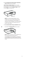
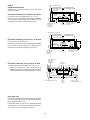
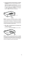
5. Remove the duct knockouts using a flat blade
screwdriver and a small hammer.
Use the screwdriver by knocking out the pannel in
similar fashion to a scalpel.
Take care of sharp edges.
Attention!
If is intended to use the hood in recirculating version do
not remove any duct knockouts and order the necessary
charcoal filter from your supplier.
Rectangular
vertical
discharge
Rectangular
horizontal
discharge
Round
vertical
discharge
R1
R1
R2
R1= Remove rectangular duct knockout only.
R2 = Remove semicircular and rectangular duct
knockouts.

9
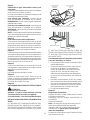
6. For rectangular ducted discharge installations
only (otherwise skip to next step)
Attach exhaust adaptor/damper over knockout
opening with two exhaust adaptor screws. Make sure
damper pivot is nearest to top/back edge of hood.
Remove tape from damper flap.
Exhaust
transition/damper
Pivot
Top/back
edge
NOTE: The exhaust adaptor/damper can be
installed up to 1 inch on either side of the hood
center to accommodate off-center ductwork. In
extreme off-center installations, one end of the duct
connector may need to be trimmed to clear the
electrical cable clamp.
7. For round ducted discharge installations only
Re-install the round transition with its screws.
7" Round
Transition
NOTE: The round transition can be installed up to 1
inch on either side of the hood center to
accommodate off-center ductwork. In extreme off-
center installations, one end of the duct connector
may need to be trimmed to clear the electrical cable
clamp.

10
8. Mark holes
Select the vent option that your installation will
require and proceed to that section:
Outside top exhaust
(Vertical duct– 3 1/4”x 10” Rectangular)
Use the diagram or the hood as a template and
mark the locations on the cabinet for ductwork,
electrical wiring and keyhole screw slots.
Outside top exhaust
(Vertical duct–7” Round)
Use the diagram or the hood as a template and
mark the locations on the cabinet for ductwork,
electrical wiring and keyhole screw slots.
Outside rear exhaust
(Horizontal duct– 3 1/4”x 10” Rectangular)
• Use the diagram or the hood as a template and
mark the locations on the cabinet for ductwork,
electrical wiring and keyhole screw slots.
Recirculating
Use the hood as a template and mark the locations
on the cabinet for the electrical wiring and keyhole
screw slots.
Since the hood is to be recirculated (not to be
vented outside), do not cut out any vent openings in
the wall or cabinet bottom.
Hood mounting screws (4)
1 1/4"
"
"
"
Center
line
Electrical access hole
(in cabinet bottom)
Wood shims (recessed
bottom cabinets only)
Vertical duct
access hole
13 15/16" (30" Hood)
16 15/16" (36" Hood)
13 15/16" (30" Hood)
16 15/16" (36" Hood)
Cabinet front
10 1/2"
Electrical access hole
(in cabinet
bottom)
5"
1 1/4"
Cabinet Bottom
12 9/16"
5 1/4"
5 1/4"
2"
Hood mounting screws (4)
1 1/2"
"
Center
line
Electrical access hole
(in cabinet bottom)
Wood shims (recessed
bottom cabinets only)
13 15/16" (30" Hood)
16 15/16" (36" Hood)
13 15/16" (30" Hood)
16 15/16" (36" Hood)
Cabinet front
10 1/2"
Electrical access hole
(in cabinet
bottom)
Cabinet Bottom
12 1/2"
2 1/4"
8" DIA.
HOLE
5"
Access
hole for 7"
round duct
Center line
Hood mounting screws (4)
Wood shims (recessed
bottom cabinets only)
Cabinet front
Electrical access hole
(in wall)
Cabinet
bottom
1/8"
7/16"
13 15/16" (30" Hood)
16 15/16" (36" Hood)
13 15/16" (30" Hood)
16 15/16" (36" Hood)
Horizontal duct
access hole
5 1/4" 5 1/4"
12 7/16"
3 3/4"

11
9. Choose Venting Option
The hood can be set to vent outside or to
recirculate air back into the kitchen.
The plastic vent lever is located near the center
of the hood opening.
To vent to the outside, make sure the plastic
vent lever is in the HORIZONTAL position (flat
against the metal top of the hood).
To recirculate air into the kitchen, make sure
the plastic vent lever is in the VERTICAL
position (flat against the plastic blower housing).
NOTE: In order to change the vent lever
position, you will need to pull the lever out
slightly to clear the plastic tabs.
10.For recessed bottom cabinet only
If the cabinets have front, side or back trim,
make 2 wood shims the width of the trim and
attach them to the cabinet bottom recess on
both sides. See previous page for marking
locations.
11.Cut holes at marked locations for duct and
electrical wiring. For the vertical duct, cut out 3/
4” extra toward the front of the cabinet so you
can move the duct freely when installing the
hood.
It may also ease installation by cutting the hole
10 1/2” instead of 10”.
12.Drive a mounting screw (from the hardware
packet) partway into each center of the narrow
neck of the keyhole slots marked on the cabinet
bottom.
13.Fix the wiring conduit to the hood.
14.Slide the hood back against the wall. Tighten
the mounting screws. Be sure the screw heads
are in the narrow neck of the keyhole slot.
Connect Ductwork to hood.
15.WIRING THE HOOD
WARNING
Electrical Shock Hazard
Warning: Turn off power at the service panel
before wiring this unit.
120 VAC, 15 or 20 Amp circuit required.
ELECTRICAL GROUNDING INSTRUCTIONS
THIS APPLIANCE IS FITTED WITH AN
ELECTRICAL JUNCTION BOX WITH 3 WIRES,
ONE OF WHICH (GREEN/YELLOW) SERVES TO
GROUND THE APPLIANCE. TO PROTECT YOU
AGAINST ELECTRIC SHOCK, THE GREEN AND
YELLOW WIRE MUST BE CONNECTED TO THE
GROUNDING WIRE IN YOUR
HOME ELECTRICAL SYSTEM, AND IT MUST
UNDER NO CIRCUMSTANCES BE CUT OR
REMOVED.
Set for
outside venting
Set for
recirculating
Stop tab
Stop tab
Hood shown Lying upside down
Failure to do so can result in death or electrical
shock.
• If not already done, install 1/2” conduit
connector in j-box.
• Run black (live), white (neutral), and green
(earth) wires (#14 AWG) according to the
National Electrical Code or CSA Standards and
local codes and ordinances in 1/2” conduit from
power supply to j-box.
• Connect black, white, and green wires from
power supply to black (live), white (neutral), and
green/yellow (earth) wires in j-box respectively.
• These connections should be done always
making reference to the electrical diagram
found inside the hood.
• Close j-box cover.
Final installation steps
16.Replace filters as described in the Care & Use
section of this manual.
Models DUH30252UC and DUH36252UCOnly:
Install the lamps on proper housings.
Note: Lamps are not supplied, use ONLY 120
Volt, 50 Watt (maximum) 50° halogen light
made for a GU10 base, suitable for use in
open luminarie.
Turn power on at service panel. Check
operation of the hood.
Wood shims
Page is loading ...
Page is loading ...
Page is loading ...
Page is loading ...
Page is loading ...
Page is loading ...
Page is loading ...
Page is loading ...
Page is loading ...
Page is loading ...
Page is loading ...
Page is loading ...
Page is loading ...
Page is loading ...
Page is loading ...
Page is loading ...
Page is loading ...
Page is loading ...
Page is loading ...
Page is loading ...

5551 McFadden Avenue, Huntington Beach, CA 92649 • 800-944-2904• www.boschappliances.com
90000740553 • 10061 Rev B • 06/05 © BSH Ho
me Appliances Corporation 2005 • Litho U.S.A.
LI2WVB
-
 1
1
-
 2
2
-
 3
3
-
 4
4
-
 5
5
-
 6
6
-
 7
7
-
 8
8
-
 9
9
-
 10
10
-
 11
11
-
 12
12
-
 13
13
-
 14
14
-
 15
15
-
 16
16
-
 17
17
-
 18
18
-
 19
19
-
 20
20
-
 21
21
-
 22
22
-
 23
23
-
 24
24
-
 25
25
-
 26
26
-
 27
27
-
 28
28
-
 29
29
-
 30
30
-
 31
31
-
 32
32


Bosch 00466148 Installation guide
- Category
- Cooker hoods
- Type
- Installation guide
Ask a question and I''ll find the answer in the document
Finding information in a document is now easier with AI
in other languages
- français: Bosch 00466148 Guide d'installation
- español: Bosch 00466148 Guía de instalación
Related papers
-
Bosch DPH36652UC/01 Installation guide
-
Bosch DPH30652UC Installation guide
-
-
-
-
Bosch BSDUH30152UC Installation guide
-
-
-
-
Other documents
-
Electrolux 316488521 User guide
-
ELICA EAL330WT Operating instructions
-
-
ELICA EAL336S1 Owner's manual
-
Blomberg BCHS30100SS User manual
-
-
-
-
-
Jenn-Air LI3URB/W10274314C User manual